Purpose:
Familiar with the use of the IIC interface of raspberry pie through the screen display case of OLED.
catalogue
1.3.2 horizontal addressing mode
1.3.3 vertical addressing mode
1.4 interface usage of IIC on raspberry pie
1.4.2 function of initializing device ID
1.4.3 function of reading device node value
1.4.4 function to write value to equipment node
1.4.5 write a value to a register of the device node
1.4.6 read the value of a register of the device node
2.2.1 implementation of header file
2.2.3. Update video memory function
2.2.4 lighting screen function
2.2.6 OLED screen clearing function
2.2.7 OLED point drawing function
2.2.8 OLED screen filling function
2.2.9 OLED screen initialization function
2.2.10 setting cursor point function for OLED
2.2.11 OLED display character function
2.2.12 OLED display digital function
2.2.13 OLED display string function
2.3. Generate execution program
1. Basic knowledge
1.1 introduction to OLED
OLED (organic light emitting diode), namely organic light emitting diode, is a new product on mobile phone OLED and is known as "dream display". OLED display technology is different from the traditional LCD display mode. It does not need backlight. It adopts very thin organic material coating and glass substrate (or flexible organic substrate). When there is current, these organic materials will emit light. Moreover, the OLED display screen can be made lighter and thinner, with a larger viewing angle, and can significantly save power consumption.
OLED display principle is essentially different from LCD. It is mainly driven by electric field. Organic semiconductor materials and light-emitting materials emit light through overload streamer injection and recombination. In essence, the ITO glass transparent electrode is used as the device anode and the metal electrode as the cathode. Driven by the power supply, electrons are transmitted from the cathode to the electron transport layer, holes are injected from the anode to the hole transport layer, and then migrate to the light-emitting layer. After they meet, excitons are generated to excite the light-emitting molecules, and the light source is generated after radiation. In short, an OLED screen is composed of millions of "small bulbs".
This case uses a 0.96 inch OLED display driven by SSD1306. SSD1306 is a monolithic CMOS OLED/PLED driver with controller for OLED dot matrix graphics display system. It consists of 128 SEG S (column output) and 64 COM (row output). The chip is designed for common cathode OLED panel.
SSD1306 has built-in contrast controller, display RAM (GDDRAM) and oscillator, so as to reduce the number and power consumption of external components. The chip has 256 levels of brightness control. Data or commands are sent by the general microcontroller through the 6800 / 8000 Series general parallel interface, I2C interface or serial peripheral interface selected by hardware. The chip is suitable for many small portable applications, such as mobile phone secondary display, MP3 player and calculator.
1.2 OLED initialization
Refer to the OLED data manual. The OLED initialization steps are as follows.
- (1)Set MUX Ratio A8h, 3Fh
- (2)Set Display OffsetD3h, 00h
- (3)Set Display StartLine 40h
- (4)Set Segment re-mapA0h/A1h
- (5)Set COM Output ScanDirection C0h/C8h
- (6)Set COM Pinshardware configuration DAh,02h
- (7)Set Contrast Control 81h,7Fh
- (8)Disable EntireDisplay On A4h
- (9)Set Normal DisplayA6h
- (10)Set Osc FrequencyD5h, 80h
- (11)Enable charge pumpregulator 8Dh, 14h
- (12)Display On AFh
1.3 OLED display
To know where to display, you need to know where to display. The resolution of oled module is 128 × 64, that is, a total of 128 can be displayed × 64 for so many "points", let's use a 128 column and 64 row table to describe them more clearly, as shown below:
| Col0 | Col1 | Col2 | Col3 | Col4 | ...... | Col125 | Col126 | Col127 | |||
|---|---|---|---|---|---|---|---|---|---|---|---|
| PAG0 | bit0 | Row0 | 0 | ||||||||
| bit1 | Row1 | 1 | |||||||||
| bit2 | Row2 | 0 | |||||||||
| bit3 | Row3 | 0 | |||||||||
| bit4 | Row4 | 0 | |||||||||
| bit5 | Row5 | 1 | |||||||||
| bit6 | Row6 | 0 | |||||||||
| bit7 | Row7 | 1 | |||||||||
| PAG1 | bit0 | Row8 | |||||||||
| bit1 | Row9 | ||||||||||
| bit2 | Row10 | ||||||||||
| bit3 | Row11 | ||||||||||
| bit4 | Row12 | ||||||||||
| bit5 | Row13 | ||||||||||
| bit6 | Row14 | ||||||||||
| bit7 | Row15 | ||||||||||
| PAG2 | |||||||||||
| PAG3 | |||||||||||
| PAG4 | |||||||||||
| PAG5 | |||||||||||
| PAG6 | |||||||||||
| PAG7 |
Each point on the display module corresponds to a space in the table. If you put 1 in a space to indicate that the 'point' is bright, then 0 means that the 'point' is dark. Since we usually write data in bytes, now take Row0-Row7 corresponding to Col0 column in the table as a unit, a total of 8 spaces, just corresponding to one byte.
How to allocate the high and low bits of this byte? The lowest bit is placed in the space corresponding to Row0-Col0, and the highest bit is placed in the space corresponding to Row7-Col0. In this way, when you write a byte of data 0x08, the corresponding "point" of Col0-Row3 is on and the other seven points are dark. So where is the data 0x08 written? The display module must have a storage space to store these written data. For the time being, it is called PAGE0, page1 PAGE7. In this way, each page corresponds to 8 lines. For example, PAGE0 corresponds to Row0-Row7.
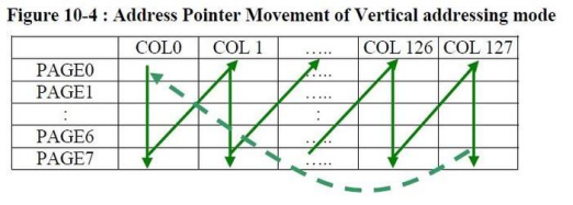
After the above analysis, the problem becomes simple, that is, how to access PAGE0-PAGE7, and then fill in the data. This involves three addressing modes: page addressing, horizontal addressing and vertical addressing. The following three figures describe these three addressing modes.
1.3.1 page addressing mode

1.3.2 horizontal addressing mode

1.3.3 vertical addressing mode

Next, check the instruction table of the OLED module specification, determine any addressing mode, and then fill in the data according to the content to be displayed.
1.4 interface usage of IIC on raspberry pie
Refer to the official link: http://wiringpi.com/reference/i2c-library/
1.4.1 header file
You need to add a header file before using the IIC interface
#include <wiringPiI2C.h>
1.4.2 function of initializing device ID
 int wiringPiI2CSetup (int devId) ;

Return to device node
1.4.3 function of reading device node value
int wiringPiI2CRead (int fd) ;
1.4.4 function to write value to equipment node
int wiringPiI2CWrite (int fd, int data) ;
1.4.5 write a value to a register of the device node
Write 1 byte
int wiringPiI2CWriteReg8 (int fd, int reg, int data) ;

Write 2 bytes
int wiringPiI2CWriteReg16 (int fd, int reg, int data) ;
1.4.6 read the value of a register of the device node
Read one byte of data
int wiringPiI2CReadReg8 (int fd, int reg) ;

Read two bytes of data
int wiringPiI2CReadReg16 (int fd, int reg) ;
2. Function realization
Through the programming of OLED screen, the display of "hello" character is realized
2.1 schematic diagram

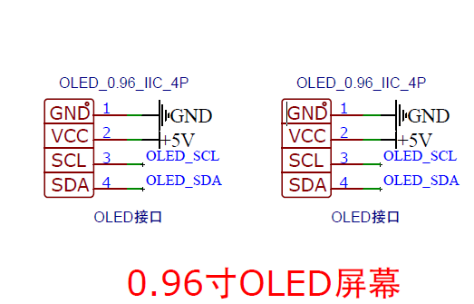
Figure 2-1-1 schematic diagram of OLED
The OLED is connected to the I2C-1 port of raspberry pie through wiring.
2.2 code implementation
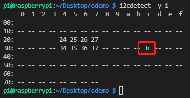
The ID address to the device through the IIC tool is 0x3C.
i2cdetect -y 1

Figure 2-2-1 IIc address of OLED
It is different from the description address 0x78 in the data manual because the 7-bit address is displayed in the Linux system.
Data book: in linux system
01111000 ---->0111100
2.2.1 implementation of header file
#include <wiringPi.h>
#include <stdio.h>
#include <stdlib.h>
#include <wiringPiI2C.h>
#include "oledfont.h"
2.2.2 macro definition
#define u8 unsigned char
#define u32 unsigned int

#Define slaveaddress 0x3c / / OLED address
#define OLED_ CMD 0x00 / / OLED write command
#define OLED_ Data 0x40 / / OLED write data

int fd;
u8 OLED_GRAM[128][8];
2.2.3. Update video memory function
//Update video memory to LCD
void OLED_Refresh_Gram(void)
{
	u8 i,n;
	for(i=0;i<8;i++)
	{
		wiringPiI2CWriteReg8 (fd,OLED_CMD,0xb0+i);    //Set page address (0 ~ 7)
		wiringPiI2CWriteReg8 (fd,OLED_CMD,0x00);      //Set display position - column low address
		wiringPiI2CWriteReg8 (fd,OLED_CMD,0x10);      //Set display position - column height address
		for(n=0;n<128;n++)wiringPiI2CWriteReg8(fd,OLED_DATA,OLED_GRAM[n][i]);
	}
}
2.2.4 lighting screen function
/open OLED display
void OLED_Display_On(void)
{
	wiringPiI2CWriteReg8(fd,OLED_CMD,0X8D);  //SET DCDC command
	wiringPiI2CWriteReg8(fd,OLED_CMD,0X14);  //DCDC ON
	wiringPiI2CWriteReg8(fd,OLED_CMD,0XAF);  //DISPLAY ON
}
2.2.5. Close screen function
//Turn off OLED display
void OLED_Display_Off(void)
{
	wiringPiI2CWriteReg8(fd,OLED_CMD,0X8D);  //SET DCDC command
	wiringPiI2CWriteReg8(fd,OLED_CMD,0X10);  //DCDC OFF
	wiringPiI2CWriteReg8(fd,OLED_CMD,0XAE);  //DISPLAY OFF
}
2.2.6 OLED screen clearing function
//Clear screen function, clear the screen, the whole screen is black! It's the same as not lit!!!
void OLED_Clear(void)
{
	u8 i,n;
	for(i=0;i<8;i++)for(n=0;n<128;n++) OLED_GRAM[n][i]=0X00;
	OLED_Refresh_Gram();//update display
}
2.2.7 OLED point drawing function
//Draw point
//x:0~127
//y:0~63
//t:1 fill 0, empty
void OLED_DrawPoint(u8 x,u8 y,u8 t)
{
	u8 pos,bx,temp=0;
	if(x>127||y>63)return;//Out of range
	pos=7-y/8;
	bx=y%8;
	temp=1<<(7-bx);
	if(t)OLED_GRAM[x][pos]|= temp;
	else OLED_GRAM[x][pos]&=~temp;
}
2.2.8 OLED screen filling function
//x1,y1,x2,y2 diagonal coordinates of the filled area
//Ensure that X1 < = x2; y1<=y2 0<=x1<=127 0<=y1<=63
//dot:0, clear; 1. Filling
void OLED_Fill(u8 x1,u8 y1,u8 x2,u8 y2,u8 dot)
{
	u8 x,y;
	for(x=x1;x<=x2;x++)
	{
		for(y=y1;y<=y2;y++)OLED_DrawPoint(x,y,dot);
	}
	OLED_Refresh_Gram();//update display
}
2.2.9 OLED screen initialization function
//Screen initialization function
int oled_init(void)
{
    wiringPiSetup();
    fd = wiringPiI2CSetup (SlaveAddress);
    if(fd < 0)
    {
        printf("IIC initialization failed\r\n");
        return fd;
    }

    wiringPiI2CWriteReg8(fd,OLED_CMD,0xAE);  //Turn off display
    wiringPiI2CWriteReg8(fd,OLED_CMD,0xD5);  //Set clock frequency division factor and oscillation frequency
    wiringPiI2CWriteReg8(fd,OLED_CMD,0x50);  //[3:0], frequency division factor; [7:4], oscillation frequency
    wiringPiI2CWriteReg8(fd,OLED_CMD,0xA8);  //Set the number of drive paths
    wiringPiI2CWriteReg8(fd,OLED_CMD,0x3F);  //Default 0X3F(1/64)
    wiringPiI2CWriteReg8(fd,OLED_CMD,0x00);  //The default is 0
    wiringPiI2CWriteReg8(fd,OLED_CMD,0x40);  //Set the display start line [5:0] and the number of lines

    wiringPiI2CWriteReg8(fd,OLED_CMD,0x8D);  //Charge pump settings
    wiringPiI2CWriteReg8(fd,OLED_CMD,0x14);  //bit2, on / off
    wiringPiI2CWriteReg8(fd,OLED_CMD,0x20);  //Set memory address mode
    wiringPiI2CWriteReg8(fd,OLED_CMD,0x02);  //[1:0], 00, column address mode; 01, line address mode; 10. Page address mode; Default 10;
    wiringPiI2CWriteReg8(fd,OLED_CMD,0xA1);  //Segment redefinition setting, bit0:0,0 - > 0; 1,0->127;
    wiringPiI2CWriteReg8(fd,OLED_CMD,0xC0);  //Set com scanning direction; bit3:0, normal mode; 1. Redefine the mode com [n-1] - > COM0; N: Number of driving paths
    wiringPiI2CWriteReg8(fd,OLED_CMD,0xDA);  //Set COM hardware pin configuration
    wiringPiI2CWriteReg8(fd,OLED_CMD,0x12);  //[5:4] configuration
    wiringPiI2CWriteReg8(fd,OLED_CMD,0x81);  //Contrast setting
    wiringPiI2CWriteReg8(fd,OLED_CMD,0xEF);  //1~255; Default 0X7F (brightness setting, bigger, brighter)
    wiringPiI2CWriteReg8(fd,OLED_CMD,0xD9);  //Set precharge cycle
    wiringPiI2CWriteReg8(fd,OLED_CMD,0xF1);  //[3:0],PHASE 1;[7:4],PHASE 2;
    wiringPiI2CWriteReg8(fd,OLED_CMD,0xDB);  //Set VCOMH voltage magnification
    wiringPiI2CWriteReg8(fd,OLED_CMD,0x30);  //[6:4] 000,0.65*vcc;001,0.77*vcc;011,0.83*vcc;

    wiringPiI2CWriteReg8(fd,OLED_CMD,0xA4);  //Global display on; bit0:1, on; 0, off; (white / black screen)
    wiringPiI2CWriteReg8(fd,OLED_CMD,0xA6);  //Set the display mode; bit0:1, inverted display; 0, normal display
    wiringPiI2CWriteReg8(fd,OLED_CMD,0xAF);  //Turn on display

    OLED_Clear();
    return 0;
}
2.2.10 setting cursor point function for OLED
//Set cursor
void OLED_SetPos(u8 x, u8 y)
{
    wiringPiI2CWriteReg8(fd,OLED_CMD,0xB0+y);
    wiringPiI2CWriteReg8(fd,OLED_CMD,((x&0xf0)>>4)|0x10);
    wiringPiI2CWriteReg8(fd,OLED_CMD,(x&0x0f)|0x01);
}
2.2.11 OLED display character function
//Displays a character in the specified position, including some characters
//x:0~127
//y:0~63
//mode:0, negative display; 1. Normal display
//size: select font 16 / 12
void OLED_ShowChar(u8 x,u8 y,u8 chr,u8 size,u8 mode)
{
	u8 temp,t,t1;
	u8 y0=y;
	u8 csize=(size/8+((size%8)?1:0))*(size/2);		//Get the number of bytes in the lattice set corresponding to one character of the font
	chr=chr-' ';//Get the offset value
    for(t=0;t<csize;t++)
    {
		if(size==12)temp=asc2_1206[chr][t]; 	 	//Call 1206 font
		else if(size==16)temp=asc2_1608[chr][t];	//Call 1608 font
		else if(size==24)temp=asc2_2412[chr][t];	//Call 2412 font
		else return;								//No font
        for(t1=0;t1<8;t1++)
		{
			if(temp&0x80)OLED_DrawPoint(x,y,mode);
			else OLED_DrawPoint(x,y,!mode);
			temp<<=1;
			y++;
			if((y-y0)==size)
			{
				y=y0;
				x++;
				break;
			}
		}
    }
}
//m^n function
u32 mypow(u8 m,u8 n)
{
	u32 result=1;
	while(n--)result*=m;
	return result;
}
2.2.12 OLED display digital function
//Display 2 numbers
//x. Y: starting point coordinates
//len: number of digits
//Size: font size
//Mode: mode 	 0, filling mode; 1. Superposition mode
//num: value (0 ~ 4294967295);
void OLED_ShowNum(u8 x,u8 y,u32 num,u8 len,u8 size)
{
	u8 t,temp;
	u8 enshow=0;
	for(t=0;t<len;t++)
	{
		temp=(num/mypow(10,len-t-1))%10;
		if(enshow==0&&t<(len-1))
		{
			if(temp==0)
			{
				OLED_ShowChar(x+(size/2)*t,y,' ',size,1);
				continue;
			}else enshow=1;

		}
	 	OLED_ShowChar(x+(size/2)*t,y,temp+'0',size,1);
	}
}
2.2.13 OLED display string function
//display string
//x. Y: starting point coordinates
//Size: font size
//*p: String start address
void OLED_ShowString(u8 x,u8 y,const u8 *p,u8 size)
{
    while((*p<='~')&&(*p>=' '))//Judge whether it is an illegal character!
    {
        if(x>(128-(size/2))){x=0;y+=size;}
        if(y>(64-size)){y=x=0;OLED_Clear();}
        OLED_ShowChar(x,y,*p,size,1);
        x+=size/2;
        p++;
    }

}
2.2.14 main function
int main(void)
{
    int ret;

    ret = oled_init();
    if(ret != 0)
    {
        printf("OLED init error \r\n");
        return -1;
    }


    OLED_ShowString(0,0,(const u8 *)("hello"),24);
    OLED_Refresh_Gram();//update display

    return 0;
}
2.3. Generate execution program
The wiringPi library needs to be added during compilation. The compilation steps are as follows:
gcc -Wall -o oled oled.c -lwiringPi

2.4 function realization
Execution procedure
./oled
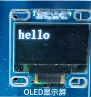
The word hello is displayed on the OLED screen.

Figure 2-4-1 shows the results