4.10 use the counter to measure the pulse frequency of NE555
4.10. 1 Introduction to schematic diagram
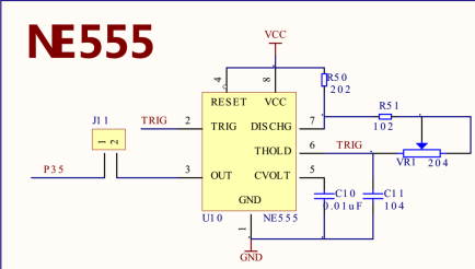
Figure 4-10-1
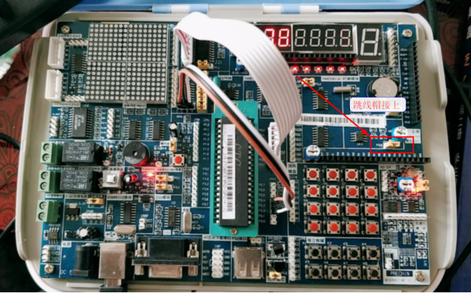
Figure 4-10-2
4.10. 2 introduction of counter mode of single chip microcomputer
Two 16 bit timers / counters t0 and T1 set inside STC90C51RC/RD + series single chip microcomputer have two working modes: counting mode and timing mode. For each timer / counter (T0 and T1), there is a control - C/T in the special function register TMOD to select whether t0 or T1 is a timer or a counter. The core component of timer / counter is an addition counter, whose essence is to count pulses. Only the counting pulse sources are different: if the counting pulse comes from the system clock, it is the timing mode. At this time, the timer / counter obtains a counting pulse every 12 clocks or every 6 clocks, and the count value is added by 1; If the counting pulse comes from the external pin of the single chip microcomputer (t0 is P3.3,T1 is P3.3), it is the counting mode, and 1 is added for each pulse.
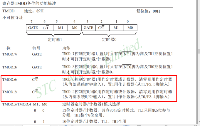
Figure 4-10-3
4.10. 3 Introduction to NE555 timer
555 timer is an integrated circuit chip, which is often used in timer, pulse generator and oscillation circuit. 555 can be used as a delay device, trigger or vibration starting element in the circuit.
555 timer can work in three working modes:
Monostable mode: in this mode, 555 function is single trigger. Applications include timer, pulse loss detection, bounce switch, touch switch, frequency divider, capacitance measurement, pulse width modulation (PWM), etc.
No steady state mode: in this mode, 555 operates as an oscillator. 555 chip in this working mode is often used in strobe lamp, pulse generator, logic circuit clock, tone generator, pulse position modulation (PPM) and other circuits. If thermistor is used as timing resistor, 555 can form a temperature sensor, and the frequency of its output signal is determined by temperature.
Bistable mode (or Schmitt trigger mode): when DIS pin is empty and no external capacitor is connected, 555 works similar to an RS trigger and can be used to form a latch switch.
4.10. 4 example code
In the following code, configure timer 1 to 16 bit counter mode and turn on counting interrupt; NE555 pulse generator is connected to P3 The 3-pin input pulse is counted by timer 1. Reconfigure timer 0 to 16 bit timer mode, timeout once in 50 milliseconds, and record the timeout times in the interrupt service function. When timeout 20 times, it means that 1 second time has arrived. After 1 second, turn off timer 0 and counter 1 in the interrupt service function of timer 0. Judge whether the counter stops in the main function. How to stop the counter means that 1 second time has arrived. Then read the number of pulses recorded by counter 1 within 1 second and display it through nixie tube.
The pulse period can be obtained by using the total pulse impulse / total time.
Example code:
#include <reg51.h>
u32 time1_cnt=0; //Record the number of external pulses received by counter 1
u32 time0_cnt=0; //Record the timeout times of timer 0
u32 Freq=0;
int main()
{
    Timer0_16bit_Init(50000); //Initialize timer 0, with a timing of 50ms
    Timer1_16bit_CntMode_Init(); //Initialize counter 1
    while(1)
    {
        if(TR0==0) //When timer 0 stops, it indicates that 1 second time has arrived
        {
            Freq=time1_cnt+(TH1<<8|TL1); //Get the number of pulses calculated in 1 second
            time1_cnt=0;//Clear pulse count
            TH1=0; //Clear the value of the counter
            TL1=0;
            TR0=1; //Start timer 0
            TR1=1; //Turn on counter 1
        }
        LED_DisplayNumber(Freq); //Displays the number of pulses
    }
}

//Common cathode nixie tube code (output 1 for the segment to be displayed)
//Number 0 ~ 9
code u8 LED2_Coding[]={0x3F,0x06,0x5B,0x4F,0x66,0x6D,0x7D,0x07,0x7F,0x6F};
//Define 38 decoder pins
sbit HC138_A0=P2^2; //A
sbit HC138_A1=P2^3; //B
sbit HC138_A2=P2^4; //C
#Define LED P0 / / define LED pin

//Set the nixie tube to display the specified number
void LED_DisplayNumber(unsigned long number)
{
    u16 i,j;
    u8 display_data[8];//Store the data displayed by the current nixie tube
    //The following code extracts number in decimal order from low to high and turns it into nixie tube display characters
    display_data[0] = LED2_Coding[number/10000000%10];
    display_data[1] = LED2_Coding[number/1000000%10];
    display_data[2] = LED2_Coding[number/100000%10];
    display_data[3] = LED2_Coding[number/10000%10];
    display_data[4] = LED2_Coding[number/1000%10];
    display_data[5] = LED2_Coding[number/100%10];
    display_data[6] = LED2_Coding[number/10%10];
    display_data[7] = LED2_Coding[number/1%10];
    for(i=0;i<8;i++)
    {
        switch(i)    //Bit selection, select the lit nixie tube,
        {
            case 0:
                HC138_A0=0;HC138_A1=0;HC138_A2=0; break;//Display bit 0
            case 1:
                HC138_A0=1;HC138_A1=0;HC138_A2=0; break;//Display bit 1
            case 2:
                HC138_A0=0;HC138_A1=1;HC138_A2=0; break;//Display 2nd bit
            case 3:
                HC138_A0=1;HC138_A1=1;HC138_A2=0; break;//Display 3rd bit
            case 4:
                HC138_A0=0;HC138_A1=0;HC138_A2=1; break;//The 4th digit is displayed
            case 5:
                HC138_A0=1;HC138_A1=0;HC138_A2=1; break;//The 5th digit is displayed
            case 6:
                HC138_A0=0;HC138_A1=1;HC138_A2=1; break;//Bit 6 is displayed
            case 7:
                HC138_A0=1;HC138_A1=1;HC138_A2=1; break;//Bit 7 is displayed
        }
        LED=display_data[i];     //Control the display data value of nixie tube
        j = 100;                 //Scan interval setting
        while(j--){}
        LED=0x00;             //Blanking, all nixie tubes are not displayed
    }
}

u16 T0_Update_data;//Initial value of timer 0
void Timer0_16bit_Init(u16 us)
{
    //At present, the actual frequency of the crystal oscillator on the experimental board is 12MHZ
    u16 val=us/(12/12); //Get the count time, as long as the integer part
    T0_Update_data=65535-val; //Get the reload value
    TMOD&=0xF0;     //Clear configuration
    TMOD|=0x01;     //Configure timer 0 to operate in 16 bit timer mode
    TH0=T0_Update_data>>8; //Timer 0 high reassembly value
    TL0=T0_Update_data;    //Timer 0 low reassembly value
    EA=1;                  //Turn on total interrupt
    ET0=1;                 //Start timer 0 overflow interrupt
    TR0=1;                 //Start timer 0
}
//Reload value update function for timer 0
void Timer0_Update(void)
{
    TH0=T0_Update_data>>8; //Timer 0 high reassembly value
    TL0=T0_Update_data;    //Timer 0 low reassembly value
}
/*
Configure timer 1 to initialize to 16 bit counter mode
*/
void Timer1_16bit_CntMode_Init(void)
{
    //At present, the actual frequency of the crystal oscillator on the experimental board is 12MHZ
    TMOD&=0x0F; //Clear configuration
    TMOD|=0x50; //Configure timer 1 to operate in 16 bit counter mode
    EA=1;       //Turn on total interrupt
    ET1=1;      //Start timer 1 overflow interrupt
    TR1=1;      //Start timer 1
}

/*Interrupt service function for timer 0*/
void TIM0_IRQHandler(void) interrupt 1
{
    time0_cnt++;
    //Timer 0 is configured to timeout once in 50ms. If the timeout times reach 20 times, it means that it takes 1 second to arrive
    if(time0_cnt==20)
    {
        time0_cnt=0;
        TR0=0; //Turn off timer 0
        TR1=0; //Turn off counter 1
    }
    Timer0_Update(); //Reload of timer 0
}

/*Interrupt service function of timer 1*/
void TIM1_IRQHandler(void) interrupt 3  //Timer 1
{
    //The current counter is configured in 16 bit mode. Entering an interrupt means that 65536 times have been counted
time1_cnt+=65536;
}