Development board: Wildfire domineering V1
Chip: stm32f103ZET6
ADC: 1
CHANNEL: 11
GPIO: PC1
To create a new project
1. Open STM32CubeMx software
2. Select chip model: stm32f103ZETx
3. Configure project properties
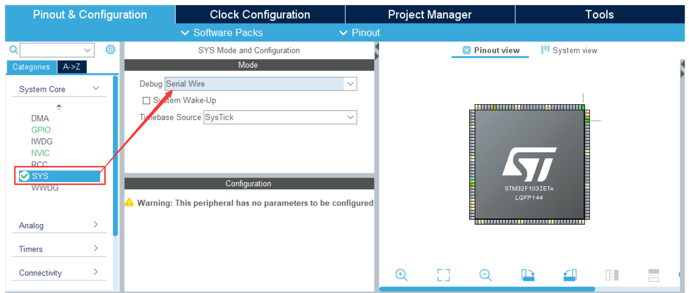
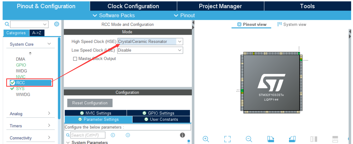
4. Confirm clock source
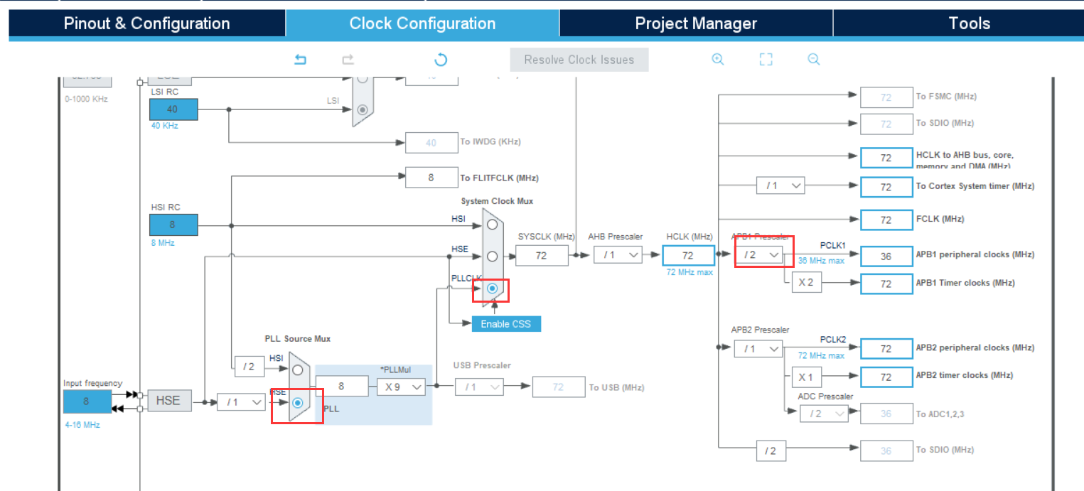
5. Configure system clock
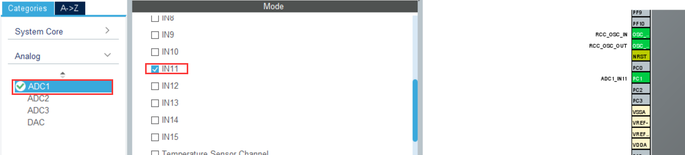
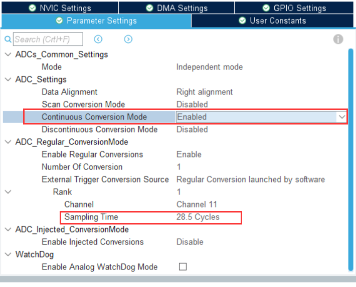
6. Open channel 11 of ADC1
7. Configuration structure
typedef struct
{
	uint32_t ADC_Mode; // ADC operating mode selection
	FunctionalState ADC_ScanConvMode; /* ADC Scan (multi-channel) or single (single channel) mode selection */
	FunctionalState ADC_ContinuousConvMode; // ADC single conversion or continuous conversion selection
	uint32_t ADC_ExternalTrigConv; // ADC conversion trigger signal selection
	uint32_t ADC_DataAlign; // ADC data register alignment format
	uint8_t ADC_NbrOfChannel; // Number of ADC acquisition channels
} ADC_InitTypeDef;
(1) ADC_Mode: configure the mode of ADC. When one ADC is used, it is independent mode, and when two ADCs are used, it is dual mode. There are many subdivision modes available in dual mode. Specifically, configure ADC_CR1:DUALMOD bit.
(2) ScanConvMode: the optional parameters are ENABLE and DISABLE. Configure whether to use scanning. If single channel AD conversion uses DISABLE, if multi-channel AD conversion uses ENABLE, configure ADC_CR1:SCAN bit
(3) ADC_ContinuousConvMode: the optional parameters are ENABLE and DISABLE, which configure whether to start automatic continuous conversion or single conversion. Use ENABLE to configure to ENABLE automatic continuous conversion; use DISABLE to configure single conversion, which stops after one conversion and needs manual control to restart the conversion. Specifically, configure ADC_CR2:CON bit
(4) ADC_ExternalTrigConv: external trigger selection. We usually use software to trigger automatically
(5) ADC_DataAlign: the data alignment mode of the conversion result. You can right align ADC_DataAlign_Right or left align ADC_DataAlign_Left. Generally, we choose the right alignment mode
(6) ADC_NbrOfChannel: the number of AD conversion channels, which can be set according to the actual settings. The specific number of channels and the conversion order of channels are to configure the regular sequence or injection sequence register
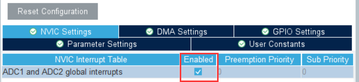
Enable interrupt
8. Configure system clock
When we enable the ADC, we will find that there is a problem with the ADC clock
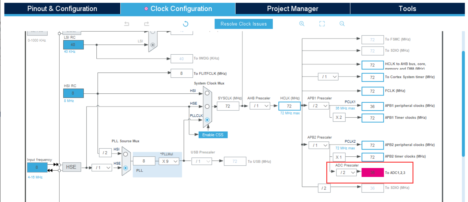
This is because the ADC input clock ADC_CLK is generated by PCLK2 through frequency division, and the maximum is 14M, so we change the frequency division factor to 6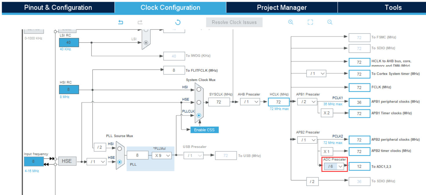
9. Generate code
Click GENERATE CODE to successfully GENERATE CODE in the set path, and select open project
Code writing
Because the code generated by CubeMx does not enable ADC and interrupt, we need to enable it manually
  LL_ADC_EnableIT_EOS(ADC1);    //Enable interrupt
  LL_ADC_Enable(ADC1);  		//Enable ADC
Then calibrate the ADC and wait until the calibration is completed. The relevant register is CR2_CAL
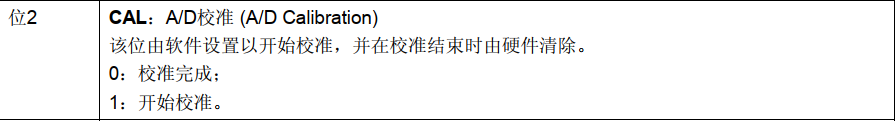
  LL_ADC_StartCalibration(ADC1);  				//Start calibration
  while (LL_ADC_IsCalibrationOnGoing(ADC1));   //Wait for calibration to complete
The software triggers the ADC and really starts the conversion
LL_ADC_REG_StartConversionSWStart(ADC1);
Interrupt function writing
This function detects the interrupt flag: LL_ADC_IsEnabledIT_EOS()
/**
  * @brief  Get state of interruption ADC group regular end of sequence conversions
  *         (0: interrupt disabled, 1: interrupt enabled).
  * @rmtoll CR1      EOCIE          LL_ADC_IsEnabledIT_EOS
  * @param  ADCx ADC instance
  * @retval State of bit (1 or 0).
  */
__STATIC_INLINE uint32_t LL_ADC_IsEnabledIT_EOS(ADC_TypeDef *ADCx)
{
  /* Note: on this STM32 serie, there is no flag ADC group regular           */
  /*       end of unitary conversion.                                         */
  /*       Flag noted as "EOC" is corresponding to flag "EOS"                 */
  /*       in other STM32 families).                                          */
  return (READ_BIT(ADCx->CR1, LL_ADC_IT_EOS) == (LL_ADC_IT_EOS));
}
This function has a clear interrupt flag: LL_ADC_ClearFlag_EOS()
/**
  * @brief  Clear flag ADC group regular end of sequence conversions.
  * @rmtoll SR       EOC            LL_ADC_ClearFlag_EOS
  * @param  ADCx ADC instance
  * @retval None
  */
__STATIC_INLINE void LL_ADC_ClearFlag_EOS(ADC_TypeDef *ADCx)
{
  /* Note: on this STM32 serie, there is no flag ADC group regular           */
  /*       end of unitary conversion.                                         */
  /*       Flag noted as "EOC" is corresponding to flag "EOS"                 */
  /*       in other STM32 families).                                          */
  WRITE_REG(ADCx->SR, ~LL_ADC_FLAG_EOS);
}
The interrupt functions are as follows:
/**
  * @brief This function handles ADC1 and ADC2 global interrupts.
  */
void ADC1_2_IRQHandler(void)
{
  /* USER CODE BEGIN ADC1_2_IRQn 0 */

	if (LL_ADC_IsEnabledIT_EOS(ADC1) == SET)
	{
		ADC_Value = LL_ADC_REG_ReadConversionData32(ADC1);

		LL_ADC_ClearFlag_EOS(ADC1);
	}

  /* USER CODE END ADC1_2_IRQn 0 */

  /* USER CODE BEGIN ADC1_2_IRQn 1 */

  /* USER CODE END ADC1_2_IRQn 1 */
}
Voltage conversion formula
ADC_ConvertedValueLocal =(float) ADC_Value/4096*3.3