An overview of dynamic routing
Dynamic routing protocol can automatically discover and generate routes, and update routes in time when topology changes. It can effectively reduce the workload of managers, and is more suitable for large-scale networks.
Automatic discovery, learning routing, sensing topology changes
II. Dynamic routing classification
Classification by work area
1 IGP (internal Gateway Protocols): RIP, OSPF, IS-IS, Cisco EIGRP
2 EGP (external gateway protocols): BGP
Classification by working mechanism and algorithm
1 (Distance Vector Routing Protocols): RIP
2 (link state routing protocols): OSPF, IS-IS
OSPF Foundation
Because the static route is manually configured by the network administrator, when the network changes, the static route needs to be adjusted manually, which restricts the large-scale application of static route in the current network.
Dynamic routing protocol is widely used in current networks because of its high flexibility, good reliability and easy expansion. Among the dynamic routing protocols, OSPF (Open Shortest Path First) protocol is one of the dynamic routing protocols with a wide range of usage scenarios.
OSPF, defined in RFC2328, is a routing protocol based on link state algorithm.
A distance vector routing protocol
Routers running distance vector routing protocols periodically flood their own routing tables. Through the interaction of routes, each router learns routes from adjacent routers and loads them into its own routing table.
For all routers in the network, the router does not know the network topology, but simply knows where to go in a certain direction and how far away it is. This is the essence of distance vector algorithm.
II. Link state routing protocol
1. LSA flooding
Unlike distance vector routing protocols, link state routing protocols advertise link states rather than routing tables. Routers running link state routing protocols will first establish a protocol neighbor relationship, and then start to interact with each other in LSA (Link State Advertisement).
Route information is no longer advertised, but LSA.
LSA describes the state information of router interface, such as interface overhead, connected object, etc.
2. Establishment of LSDB
Each router will generate LSAs, and the router will put the received LSAs into its own LSDB (Link State DataBase). The router grasps the topology of the whole network through LSDB.
The router stores the LSA in the LSDB.
LSDB summarizes the description of routers' interfaces in the network.
The LSDB contains a description of the whole network topology.
View LSDB: display ospf lsdb
3 loopback interface concept
Loopback interface is a virtual logical interface that will never be interrupted. It is often used for testing. It is no different from ordinary interfaces in essence.
Create loopback interface: interface LoopBack 0-1023
4 OSPF basic terms
region
OSPF Area is used to identify an OSPF Area.
Area logically divides devices into different groups. Each group is identified by area ID. area 0 is called the backbone area of OSPF.
Router-ID
Router ID (Router Identifier, RID) is used to uniquely identify a router in an OSPF domain.
The router ID can be set manually or automatically.
announcement
Between multiple OSPF routers. The OSPF hello messages are dynamically exchanged with each other to discover and maintain the neighbor relationship, and the subnet is involved in the dynamic calculation of OSPF.
Related commands
Create ospf process and RID: ospf process No. 1-65535 router ID ID No. X.X.X.X
Note: if only processes are created, RID will be created automatically
View OSPF information: display ospf brief
Restart OSPF process in user view: reset ospf process
Create an area under the OSPF process: Area Area No. < 0-4294967295 >
Under the interface, divide the interface into the area in the process: ospf enable process number area area number
View the adjacency status of router OSPF: display ospf peer brief
Set OSPF network type under the interface: OSPF network type?
broadcast    Specify OSPF broadcast network
  nbma       Specify OSPF NBMA network
  p2mp       Specify OSPF point-to-multipoint network
  p2p        Specify OSPF point-to-point network
Experiment: component OSPF network
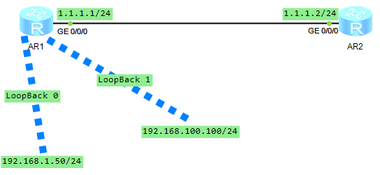
First, configure on router AR1
<AR1>system-view

[AR1]ospf 1 router id 1.1.1.1     \\establish OSPF Process and RID

[AR1-ospf-1]quit
[AR1]quit

<AR1>reset ospf process     \\restart OSPF process
Warning: The OSPF process will be reset. Continue? [Y/N]:y

<AR1>system-view
[AR1]ospf 1

[AR1-ospf-1]area 0     \\Create area

[AR1-ospf-1-area-0.0.0.0]quit
[AR1-ospf-1]quit
[AR1]interface GigabitEthernet 0/0/0

[AR1-GigabitEthernet0/0/0]ospf enable 1 area 0     \\Interface g0/0/0 Zone in progress

[AR1-GigabitEthernet0/0/0]quit
[AR1]interface LoopBack 0

[AR1-LoopBack0]ospf enable 1 area 0     \\Interface LoopBack 0 Zone in progress

[AR1-LoopBack0]quit
[AR1]interface LoopBack 1

[AR1-LoopBack1]ospf enable 1 area 0     \\Interface LoopBack 1 Zone in progress

[AR1-LoopBack1]ospf network-type broadcast      \\set up LoopBack 0 The network type of the interface is broadcast
Then configure it on router AR2
<AR2>system-view

[AR2]ospf 1 router id 1.1.1.2     \\establish OSPF Process and RID

[AR2-ospf-1]quit
[AR2]quit

<AR2>reset ospf process     \\restart OSPF process
Warning: The OSPF process will be reset. Continue? [Y/N]:y

<AR2>system-view
[AR2]ospf 1

[AR2-ospf-1]area 0     \\Create area

[AR2-ospf-1-area-0.0.0.0]quit
[AR2-ospf-1]quit
[AR2]interface GigabitEthernet 0/0/0

[AR2-GigabitEthernet0/0/0]ospf enable 1 area 0     \\Interface g0/0/0 Zone in progress
After configuration, a lot of interactive information will appear from the
[AR2-GigabitEthernet0/0/0]
Jan  1 2022 14:40:20-08:00 AR2 %%01OSPF/4/NBR_CHANGE_E(l)[0]:Neighbor changes ev
ent: neighbor status changed. (ProcessId=256, NeighborAddress=1.1.1.1, NeighborE
vent=HelloReceived, NeighborPreviousState=Down, NeighborCurrentState=Init)
[AR2-GigabitEthernet0/0/0]
Jan  1 2022 14:40:20-08:00 AR2 %%01OSPF/4/NBR_CHANGE_E(l)[1]:Neighbor changes ev
ent: neighbor status changed. (ProcessId=256, NeighborAddress=1.1.1.1, NeighborE
vent=2WayReceived, NeighborPreviousState=Init, NeighborCurrentState=2Way)
[AR2-GigabitEthernet0/0/0]
Jan  1 2022 14:40:20-08:00 AR2 %%01OSPF/4/NBR_CHANGE_E(l)[2]:Neighbor changes ev
ent: neighbor status changed. (ProcessId=256, NeighborAddress=1.1.1.1, NeighborE
vent=AdjOk?, NeighborPreviousState=2Way, NeighborCurrentState=ExStart)
[AR2-GigabitEthernet0/0/0]
Jan  1 2022 14:40:20-08:00 AR2 %%01OSPF/4/NBR_CHANGE_E(l)[3]:Neighbor changes ev
ent: neighbor status changed. (ProcessId=256, NeighborAddress=1.1.1.1, NeighborE
vent=NegotiationDone, NeighborPreviousState=ExStart, NeighborCurrentState=Exchan
ge)
[AR2-GigabitEthernet0/0/0]
Jan  1 2022 14:40:20-08:00 AR2 %%01OSPF/4/NBR_CHANGE_E(l)[4]:Neighbor changes ev
ent: neighbor status changed. (ProcessId=256, NeighborAddress=1.1.1.1, NeighborE
vent=ExchangeDone, NeighborPreviousState=Exchange, NeighborCurrentState=Loading)

[AR2-GigabitEthernet0/0/0]
Jan  1 2022 14:40:20-08:00 AR2 %%01OSPF/4/NBR_CHANGE_E(l)[5]:Neighbor changes ev
ent: neighbor status changed. (ProcessId=256, NeighborAddress=1.1.1.1, NeighborE
vent=LoadingDone, NeighborPreviousState=Loading, NeighborCurrentState=Full)
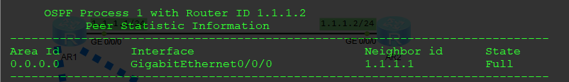
View adjacency status
[AR2]display ospf peer brief
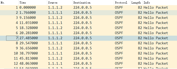
The LSA interaction between routers can be seen through packet capture
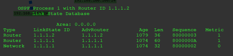
View LSDB
<AR2>display ospf lsdb
View the router information with ID 1.1.1.1 in LSDB
<AR2>display ospf lsdb router 1.1.1.1

5 SPF calculation
Each router is based on LSDB and calculated using SPF (Shortest Path First) algorithm. Each router calculates a "tree" with its own root, acyclic and shortest path. With this "tree", the router already knows the preferred path to all corners of the network.
6 routing table generation
Finally, the router loads the calculated preferred path into its Routing Table.
Each router loads the route into the routing table according to the SPF calculation results.
View the routing table of router AR2
[AR2]display ip routing-table
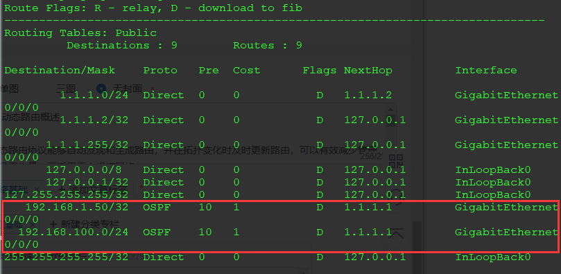
Two OSPF messages are found, indicating that the configuration is successful.