CMP projection is to project the sphere onto the cube, but the perspective projection process does not change the size of the solid angle, that is, the two points corresponding to the equal solid angle on the sphere will have high density in the central area and low density in the edge area after being projected onto the cube, resulting in poor projection uniformity. When the used projection body is closer to the sphere, the uniformity of the projection is better, and the uniformity of the octahedron projection format (OHP) projection is better than that of the sphere CMP Better, and the computational complexity increases accordingly.
OHP projection model has 8 faces (marked as F0, F1, F2, F3, F4, F5, F6,F7), each face is an equilateral triangle and has 6 angles (marked as V0,V1,V2,V3,V4,V5), as shown in Figure 1.
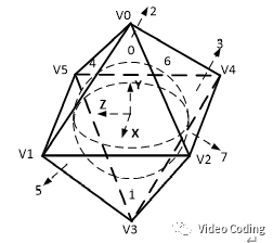
Figure 1 definition of OHP model face and angle
OHP has compact and non compact projection modes. The (X,Y,Z) coordinates of the six angles of the two modes are defined in Table 1,
Table 1 # XYZ coordinate definition of OHP angle
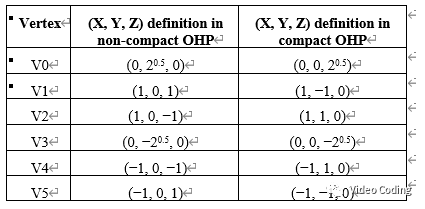
Table 2. Defining faces with corners in OHP
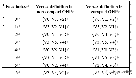
Table 2 defines 8 faces with 6 corners.
Frame Packing
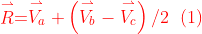
OHP projection can be expanded into 2D plane in two ways: compact and non compact.
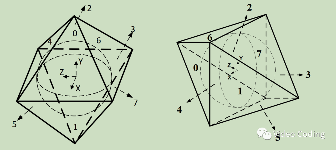
Figure 2. OHP compact and non compact formats
Figure 2 shows two projection formats of OHP. The expansion of the positive 2D plane is shown in Figure 3. Figure 3(a) is a non compact expansion method, and there are some invalid filling contents on the 2D plane. In Fig. 3(b)(c), in order to place eight triangles on a rectangular plane, faces 2 and 3 are vertically divided into faces 2-1 and 3-1 and faces 2-2 and 3-2. Non compact projection will project the content on the equator of the sphere onto the edge of the triangle. Compact projection will rotate the octahedron by 90 degrees, and the content on the equator will be projected onto the surface of the triangle [1].
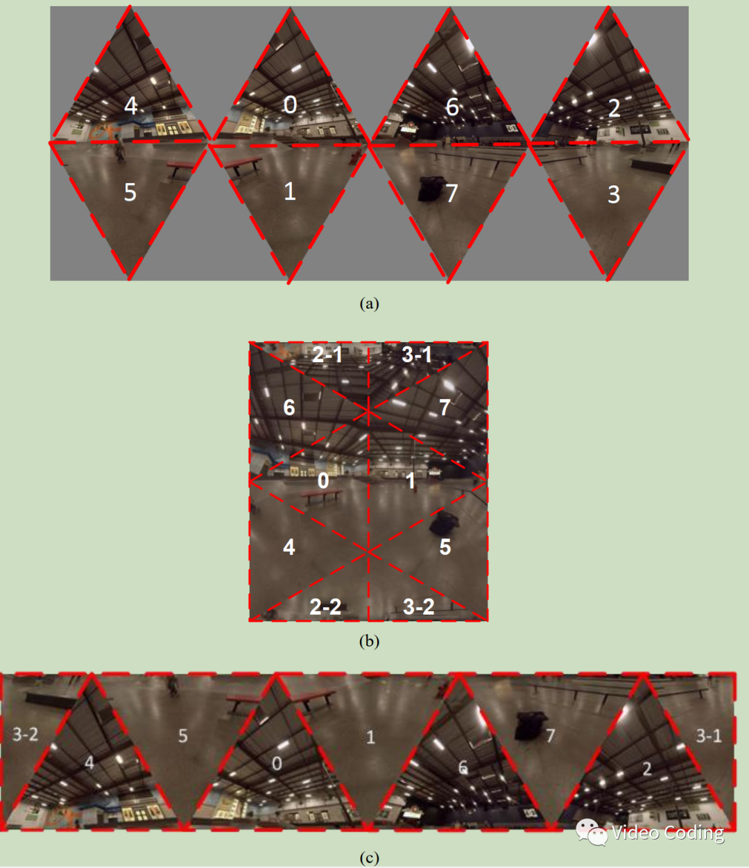
Figure 3 OHP frame packing
Projection transformation
Before introducing the projection transformation between 2D and 3D of OHP, make some symbol definitions. Figure 4 is a side view of a face of the octahedron wrapping the sphere. This face is surrounded by a rectangle, the upper left corner of the rectangle is R, its coordinates are (X_R,Y_R,Z_R), and the vector is defined as .
.
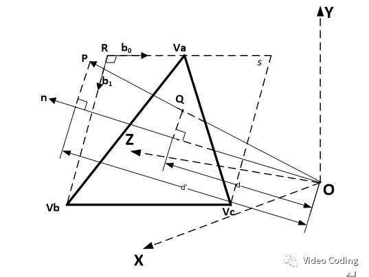
Figure 4. One face of octahedron
The three fixed points of a triangle are defined as , thenCan be generated by formula (1),
Define two orthogonal basis vectors on the face,
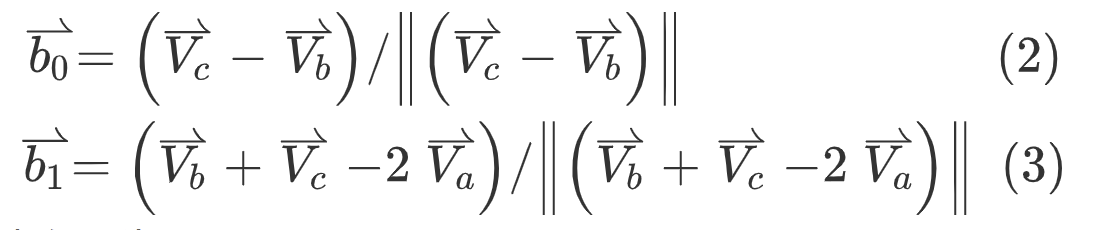
Then the normal vector of the face is,
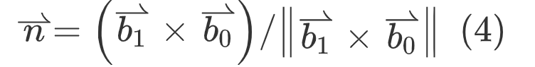
The 2D to 3D coordinates are mapped to,
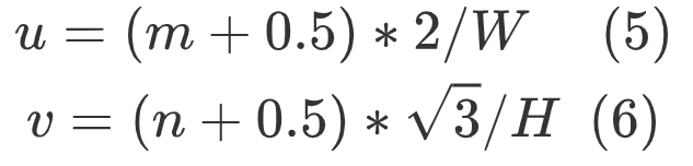
1. First, obtain (u,v) according to (m,n),
2. (X,Y,Z) can be obtained from (u,v),
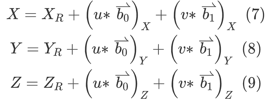
The subscript of X represents the corresponding vector, where y represents the corresponding vector.
The 3D to 2D coordinates are mapped to,
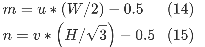
1. For the point P on the sphere, first find the index of the surface according to formula (10)
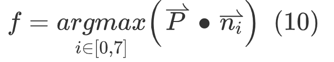
2. The projection point Q of point P on face f is calculated as follows, where , is the normal vector of face F,
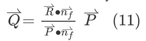
3. The coordinates (u,v) can be obtained from the basis vector of face f,
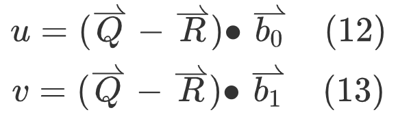
4. The final (m,n) is obtained according to the following formula,
Void TOctahedron::map2DTo3D(SPos& IPosIn, SPos *pSPosOut)
{
  pSPosOut->faceIdx = IPosIn.faceIdx;
  POSType u, v;
  POSType pu, pv; //positin in the plane of unit sphere;
  u = IPosIn.x;
  v = IPosIn.y;
  u += (POSType)(0.5);
  v += (POSType)(0.5);
  pu = (POSType)((2.0*u)/m_sVideoInfo.iFaceWidth);
  pv = (POSType)((ssqrt(3.0f)*v)/m_sVideoInfo.iFaceHeight);
  pSPosOut->x = m_meshFaces[pSPosOut->faceIdx].origin[0] + pu*m_meshFaces[pSPosOut->faceIdx].baseVec[0][0] + pv*m_meshFaces[pSPosOut->faceIdx].baseVec[1][0];
  pSPosOut->y = m_meshFaces[pSPosOut->faceIdx].origin[1] + pu*m_meshFaces[pSPosOut->faceIdx].baseVec[0][1] + pv*m_meshFaces[pSPosOut->faceIdx].baseVec[1][1];
  pSPosOut->z = m_meshFaces[pSPosOut->faceIdx].origin[2] + pu*m_meshFaces[pSPosOut->faceIdx].baseVec[0][2] + pv*m_meshFaces[pSPosOut->faceIdx].baseVec[1][2];
}

Void TOctahedron::map3DTo2D(SPos *pSPosIn, SPos *pSPosOut)
{
  Int iFaceIdx=0;
  POSType dMax = std::numeric_limits<POSType>::min();
  POSType pu, pv;
  //determine face idx;
  for(Int f=0; f<m_sVideoInfo.iNumFaces; f++)
  {
    POSType d = (pSPosIn->x*m_meshFaces[f].normVec[0] + pSPosIn->y*m_meshFaces[f].normVec[1] + pSPosIn->z*m_meshFaces[f].normVec[2]);
    if(d >dMax)
    {
      iFaceIdx = f;
      dMax = d;
    }
  }
  TriMesh& tmFace = m_meshFaces[iFaceIdx];
  POSType d = tmFace.origin[0] *tmFace.normVec[0] + tmFace.origin[1]*tmFace.normVec[1] + tmFace.origin[2]*tmFace.normVec[2];
  POSType projected[3];
  projected[0] = pSPosIn->x * d/dMax - tmFace.origin[0];
  projected[1] = pSPosIn->y * d/dMax - tmFace.origin[1];
  projected[2] = pSPosIn->z * d/dMax - tmFace.origin[2];
  pu = projected[0]*tmFace.baseVec[0][0] + projected[1]*tmFace.baseVec[0][1] + projected[2]*tmFace.baseVec[0][2];
  pv = projected[0]*tmFace.baseVec[1][0] + projected[1]*tmFace.baseVec[1][1] + projected[2]*tmFace.baseVec[1][2];
  //convert pu, pv to [0, width], [0, height];
  pSPosOut->faceIdx = iFaceIdx;
  pSPosOut->z = 0;
  pSPosOut->x = (POSType)(pu*(m_sVideoInfo.iFaceWidth>>1) + (-0.5));
  pSPosOut->y = (POSType)(pv*(m_sVideoInfo.iFaceHeight)/ssqrt(3.0f)+ (-0.5));
}
reference resources
[1] H.-C. Lin, C.-C. Huang, C.-Y. Li, Y.-H. Lee, J.-L.Lin, S.-K. Chang, "AHG8: An improvement on the compact OHP layout," Joint VideoExploration Team of ITU-T SG16 WP3 and ISO/IEC JTC1/SC29/WG11, JVET-E0056, Jan. 2017, Geneva, Switzerland.
Interested, please pay attention to WeChat official account Video Coding