In the development of industrial instruments, the physical quantities measured by the instruments are often converted into current signals for output and transmission. The characteristics of strong anti-interference and long transmission distance of current signals are widely used in industrial instruments.
ADI's AD5420 chip directly converts digital signals into current signals. Here's how to use this chip.
1, Hardware circuit design: we designed the circuit diagram according to the typical circuit in the data manual
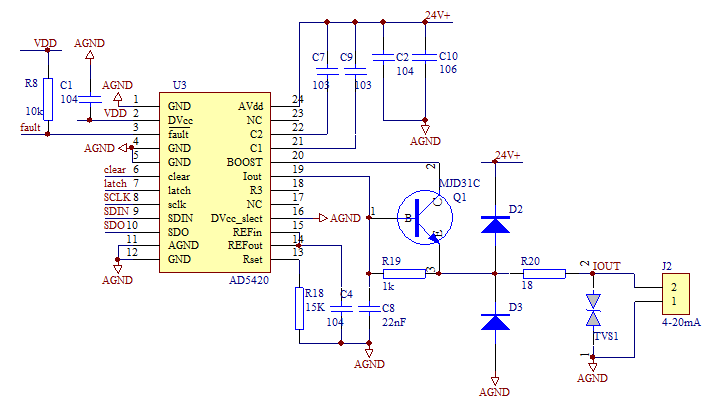
1.1 how to control AD5420 by single chip microcomputer,
mcu and AD5420 are connected through SPI interface. mcu controls the register of the chip to complete the current output and update.
So what are the operations of AD5420? Here we use the reference code provided by the official website for rapid development.
1.2 reference code
With the read-write function of AD5420, users only need to change the pin definition to correspond to their own MCU.
void delay (int length)
{
	while (length >0)
    	length--;
}


void WriteToAD5420(unsigned char count,unsigned char *Buf)
{

	unsigned	char	ValueToWrite = 0;
    unsigned	char	i = 0;
	unsigned	char	j = 0;

	CLR_LATCH();

	for ( i=count;i>0;i-- )
 	{
	 	ValueToWrite =	*(Buf+i-1);
		for (j=0; j<8; j++)
		{
			CLR_SCL();
			if(0x80 == (ValueToWrite & 0x80))
			{
				SET_SDO();	    //Send one to SDIN pin of AD5420
			}
			else
			{
				CLR_SDO();	    //Send zero to SDIN pin of AD5420
			}

			delay(1);
			SET_SCL();
			delay(1);
			ValueToWrite <<= 1;	//Rotate data
		}
	}
	CLR_SCL();
	delay(1);
	SET_LATCH();
	delay(20);
}
void ReadFromAD5420(unsigned char count,unsigned char *buf)
{
	unsigned	char	i = 0;
	unsigned	char	j = 0;
	unsigned	int  	iTemp = 0;
	unsigned	char  	RotateData = 0;

	CLR_LATCH();

	for(j=count; j>0; j--)
	{
		for(i=0; i<8; i++)
		{
		    CLR_SCL();
			RotateData <<= 1;		//Rotate data
			delay(1);
			CLR_SDO();				//write a nop condition when read the data.
			iTemp = GP0DAT;			//Read SDO of AD5420
			SET_SCL();

            if(1 == (iTemp & 0x01))
			{
				RotateData |= 1;
			}
			delay(1);

		}
		*(buf+j-1)= RotateData;
	}
	CLR_SCL();
	delay(1);
	SET_LATCH();
	delay(20);
}
How to use the function, the sample code is given in the main function.
1. Write control register

The sample code writes the control register to data 1005
    buf[2] = 0x55;
	buf[1] = 0x10;              //Disable Slew Rate
	buf[0] = 0x05;
	WriteToAD5420(3,buf);		//Write 551005 to SHIFT REGISTER  to write 1005 to control
                                                                     registe
2. Read control register
buf[2] = 0x02;
buf[1] = 0x00;
buf[0] = 0x02;
WriteToAD5420(3,buf);
ReadFromAD5420(3,buf); //Read CONTROL REGISTER
Users can learn from the function that encapsulates it into a write control register and call the function to write data flexibly.
3. Current conversion function
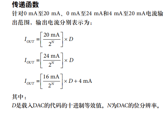
How to calculate IOUT and D in the formula
1. If there is a pressure instrument: it is required to output 4-20mA, and the full range of the instrument is 3MPA, and the output is 20mA Output 4mA when the pressure is 0
How much mA is output when the pressure is 1.5mpa?
(20-4)/3 *1.5+4=12mA, so exit the formula:
Current forward output formula: 16 / (upper limit lower limit) * (measured value lower limit) + 4
Current reverse output formula: (4-20) / (upper limit lower limit) * (measured value lower limit) + 20
Explanation: the upper and lower limits refer to the upper and lower limits of the measuring range
2. After calculating the current value, you need to calculate D, and then write D into the data register.
D=(iout-4000)*4.096 the program can be written as
D=(iout-4000)*4096/1000 is to preserve accuracy. Write the data register to output the corresponding current.