1. First attach code examples
#include <AT89X52.H>
#define uint unsigned int
#define uchar unsigned char
uint i,j;
main(){
i=0;
j=0;
EA=1; //Interrupt master switch on
ET0=1;//Timer T0 interrupt allowed
ET1=1;//Timer T1 interrupt allowed
TR0=1;// Start timer T0
TR1=1;// Start timer T1
TMOD=0x11;//Mode 1 of timer T0 mode 1 of timer T1


TH0=(65536-50000)/256; //The upper 8 bits of timer T0 are assigned with initial values
TL0=(65536-50000)%256; //The upper 8 bits of timer T0 are assigned with initial values


TH1=(65536-50000)/256; //The upper 8 bits of timer T1 are assigned initial values
TL1=(65536-50000)%256; //The upper 8 bits of timer T1 are assigned initial values


P0=0x00;   //Turn on the LED lights of all P0 ports
P1=0xff;   //Turn off the LED lights of all P1 ports
while(1); //Infinite loop,


}


/**************************************************************
Function: timer T0 interrupt service program
**************************************************************/
void int1(void) interrupt 1 //"Interrupt" declares that the function is an interrupt service function
{
i=i+1;
if(i==40){

       P0=~P0;   //The LED light at port P0 is reversed
   i=0;
}
  TH0=(65536-50000)/256; //Reset the initial value of the upper 8 bits of timer T0
TL0=(65536-50000)%256; //Reset the initial value of the upper 8 bits of timer T0
 }


 /**************************************************************
Function: timer T1 interrupt service program
**************************************************************/
void int2(void) interrupt 3 //"Interrupt" declares that the function is an interrupt service function
{

j=j+1;
if(j==40){

       P1=~P1;    //The LED of P1 port is reversed
   j=0;
}
  TH1=(65536-50000)/256; //Reset the initial value of the upper 8 bits of timer T1
TL1=(65536-50000)%256; //Reset the initial value of the upper 8 bits of timer T1

 }
2. Timer initialization
EA=1; //Interrupt master switch on
ET0=1;//Timer T0 interrupt allowed
ET1=1;//Timer T1 interrupt allowed
TR0=1;// Start timer T0
TR1=1;// Start timer T1
TMOD=0x11;//Mode 1 of timer T0 mode 1 of timer T1
Let's elaborate on why we need to configure it like this
3. Interrupt register
First, it is divided into six parts
IE   – Interrupt permission control register (key)
IP   – Interrupt priority control register
TMOD – Timer working mode register (key)
TCON – Timer control register (key)
SCON – Serial port control register
THx/TLx – Timer initial value register (key)
3.1 interrupt permission control register IE
| Serial number | D7 | D6 | D5 | D4 | D3 | D2 | D1 | D0 |
|---|---|---|---|---|---|---|---|---|
| Symbol | EA | - | ET2 | ES | ET1 | EX1 | ET0 | EX0 |
EA -Global interrupt allowed bit. When this bit is 1, interrupt is available. (important)
ET2-timer/Off allowed bit in counter 2
ES -Serial port interrupt allowed
ET1-timer/Counter 1 interrupt enable bit
EX1-External interrupt 1 allowable bit
ET0-timer/Counter 0 interrupt allowed bit (important)
EX0-External interrupt 0 allowable bit
To use timer interrupt, you need to set EA bit in IE register to 1 and ETx(x = 0,1,2) to 1
3.2 timer control register TCON
This register is used to control the interrupt, such as controlling the start and stop of the timer, and judging the overflow and interrupt of the timer.
| Serial number | D7 | D6 | D5 | D4 | D3 | D2 | D1 | D0 |
|---|---|---|---|---|---|---|---|---|
| Symbol | TF1 | TR1 | TF0 | TR0 | IE1 | IT1 | IE0 | IT0 |
TF1 Timer 1 overflow flag bit
TR1 Timer 1 runs the control bit and starts timer 1 when this position is set to 1 (important)
TF0 Timer 0 overflow flag bit
TR0 Timer 0 runs the control bit. When this position is set to 1, start timer 0 (important)
IE1 External interrupt 1 request flag
IT1 External interrupt 1 trigger mode selection bit
IE0 External interrupt 0 request flag
IT0 External interrupt 0 trigger mode selection bit
3.3 timer initial value register THx/TLx
Taking timer T0 as an example, its working principle is that whenever a pulse is generated by the crystal oscillator, the register TL0 is incremented by one. When TL0 is full and overflows, TL0 is cleared, TH0 is incremented by one, and a timing interrupt is generated after TH0 is full. That is, TH0 and TL0 form a 16 bit counter, which can be added from 0x0000 (0) to 0xffff (65535).
There are two common design methods:
First kind
TH0=(65536-50000)/256; //The upper 8 bits of timer T0 are assigned with initial values
TL0=(65536-50000)%256; //The upper 8 bits of timer T0 are assigned with initial values

TH1=(65536-50000)/256; //The upper 8 bits of timer T1 are assigned initial values
TL1=(65536-50000)%256; //The upper 8 bits of timer T1 are assigned initial values
50000 is the time we set. For example, if the mechanical cycle is 1us, then
50000*1us=50ms
This method is very intuitive. I prefer this method
Second
TH0 = 0x3c;//high position
TL0 = 0xb0; //Low position
First, put the high and low positions together
THTL=0x3cb0
Need to convert to decimal
THTL =15536
Find the time value we set
65536-15536=50000
If you want to modify the time, you also need to push back to the source, which is very troublesome. Of course, there may be other opinions to be added.
TH0 means I choose timer 0.
4. Timer working mode register TMOD

There are four modes
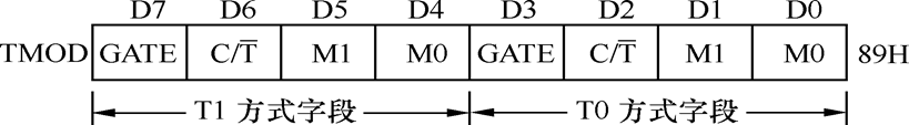
It can be seen that TO is controlled by the low four bits and T1 is controlled by the high four bits.
for instance
TMOD=0x11;//Mode 1 of timer T0 mode 1 of timer T1
According to the above, we can know
T0 timer adopts 01 working mode
T1 timer adopts 01 working mode
If you don't turn on timer 1, set it to zero
TMOD=0x01;
The following four methods are described in detail
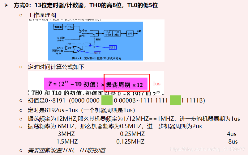
Mode 0: 13 bit timer / counter, high 8 bits of TH0 and low 5 bits of TL0
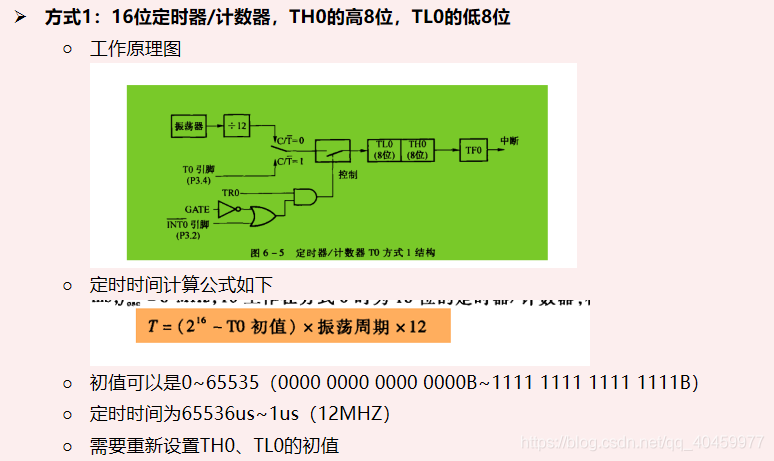
Mode 1: 16 bit timer / counter, high 8 bits of TH0 and low 8 bits of TL0
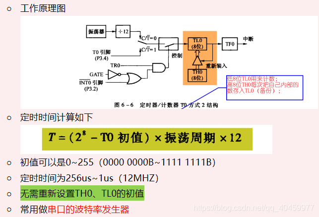
Mode 2: 8-bit counter automatically reloaded. TL0 is used for counting and TH0 is used for backup
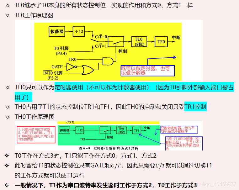
Mode 3: it is divided into two independent 8-bit counters TH0 and TL0 (only T0 can work in mode 3)
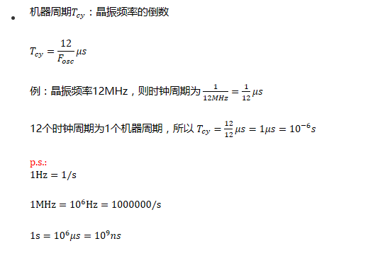
5. Clock cycle / machine cycle calculation: