Summary: Each pin of stm32 has its own special function. The pin with timer output function can output pwm. If not, it can be simulated by io port. If it is not true, it can be theoretically calculated that every pin can output PWM, but generally we use io with timer output function. This article describes in detail the use of stm32F051R8T6 MCU, with timer output function pins to output PWM waveform, the same can be achieved by other types of MCU. At the same time, the speed of DC motor is controlled. This paper takes AD0212DB-G50 DC fan produced by adda company as an example.
1. Hardware conditions
Guarantee that the output IO of single chip computer can support the function of timer. The pin connecting the fan on my board is PC9. According to the MCU manual, the pin of PC9 has the function of timer.
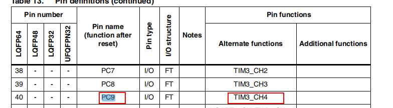
Similarly, several pins in the following figure can be used

Again, I will not list them one by one. When using different types of microcontrollers, I will refer to the manual of microcontrollers.
2.stm32 firmware library
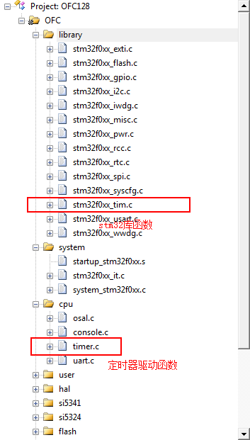
The above figure shows the library functions related to stm32 timer and the Timer Driver sub-functions related to calls, which are defined by users themselves.
The hardware and software conditions are ready, and then the configuration of pwm is needed.
1. First of all, the IO port setting of the output pin and the PWM output will naturally adopt the IO port as the output port. In the STM32F051 series, the IO port can be reused as the TIM timer output channel.
The multiplex function AF1 of PC9 is used as the fourth channel output of TIM3 timer.
2. Set the parameters of the timer and configure the PWM wave with the frequency of 17.57 KHz.
Consider the clock frequency of the time timer. If we set the frequency divider to 0, that is, the time timer equals the system clock, the system frequency has been set at 48MHZ in system_stm32f0xx.c. In startup_stm32f0xx.s, the system Init function is first run, so the time timer can be determined to run at 48MHZ.
The frequency of the PWM generated by the timer can be calculated according to the following formula:
TIM1_Period= (Time Timer Frequency / pwm Frequency) - 1
The predefined target value is actually how many times the timer runs to calculate a PWM period, which is an important parameter in setting the PWM frequency.
The complete configuration code is as follows:
/*==============================================================================
    Function name: Fan_PWMConfigInit
    Function: fan control pin output pwm control fan speed
    Input parameter description: none
    Return Value Description: None
------------------------------------------------------------------------------*/
void Fan_PWMConfigInit(void)
{
    GPIO_InitTypeDef GPIO_InitStructure;
    TIM_TimeBaseInitTypeDef TIM_TimeBaseStructure;
    TIM_OCInitTypeDef TIM_OCInitStructure;
    s32 TimerPeriod, Channel1Pulse;

    /* Enabling GPIO Clock */
    RCC_AHBPeriphClockCmd(RCC_AHBPeriph_GPIOC, ENABLE);
    /* Configure GPIO pin parameter settings*/
    GPIO_InitStructure.GPIO_Pin = GPIO_Pin_9;
    GPIO_InitStructure.GPIO_Mode = GPIO_Mode_AF;
    GPIO_InitStructure.GPIO_Speed = GPIO_Speed_50MHz;
    GPIO_InitStructure.GPIO_OType = GPIO_OType_PP;
    GPIO_InitStructure.GPIO_PuPd = GPIO_PuPd_UP;
    GPIO_Init(GPIOC, &GPIO_InitStructure);
    /* GPIO Pin Reuse Settings*/
    GPIO_PinAFConfig(GPIOC, GPIO_PinSource9, GPIO_AF_1);


    /*Calculate the predefined target value, that is, how many clocks are counted as a cycle*/
    TimerPeriod = (SystemCoreClock / 17570 ) - 1;
    /*Calculating the jump value of CCR1 at 50% duty cycle*/
    Channel1Pulse = (u16)(((u32)5 * (TimerPeriod - 1)) / 10);

    /* TIM3 Clock Enablation */
    RCC_APB1PeriphClockCmd(RCC_APB1Periph_TIM3, ENABLE);
    /* Time Timing Foundation Settings*/
    TIM_TimeBaseStructure.TIM_Prescaler = 0;
    TIM_TimeBaseStructure.TIM_CounterMode = TIM_CounterMode_Up;
    /* Time Timing Set to Rising Edge Computing Model*/
    TIM_TimeBaseStructure.TIM_Period = TimerPeriod;
    TIM_TimeBaseStructure.TIM_ClockDivision = 0;
    TIM_TimeBaseStructure.TIM_RepetitionCounter = 0;
    TIM_TimeBaseInit(TIM3, &TIM_TimeBaseStructure);
    /* PWM Mode Settings for Channel 1 */
    TIM_OCInitStructure.TIM_OCMode          = TIM_OCMode_PWM1;
    TIM_OCInitStructure.TIM_OutputState     = TIM_OutputState_Enable;
    TIM_OCInitStructure.TIM_OutputNState    = TIM_OutputNState_Enable;
    TIM_OCInitStructure.TIM_OCPolarity      = TIM_OCPolarity_Low;
    TIM_OCInitStructure.TIM_OCNPolarity     = TIM_OCNPolarity_High;
    TIM_OCInitStructure.TIM_OCIdleState     = TIM_OCIdleState_Set;
    TIM_OCInitStructure.TIM_OCNIdleState    = TIM_OCIdleState_Reset;
    TIM_OCInitStructure.TIM_Pulse = Channel1Pulse;
    TIM_OC4Init(TIM3, &TIM_OCInitStructure);
    /* TIM3 Calculator Enablation*/
    TIM_Cmd(TIM3, ENABLE);
    /* TIM3 Main Output Enablation */
    TIM_CtrlPWMOutputs(TIM3, ENABLE);

}
When the fan speed needs to be changed, only the duty cycle needs to be changed.
/* Fan control */
static s32 CmdFanCtrl (TCmdTbl *cmdtp, s32 argc, s8 *argv[])
{
    u8 byCmd;
    s32 Channel1Pulse;

    if (argc < 2)
		return -1;

    byCmd = strtoul(argv[1], NULL, 0);
    switch(byCmd){
    case 1:
        Channel1Pulse = (u16)(((u32)875 * 2730) / 1000);
        break;
    case 2:
        Channel1Pulse = (u16)(((u32)75 * 2730) / 100);
        break;
    case 3:
        Channel1Pulse = (u16)(((u32)625 * 2730) / 1000);
        break;
    case 4:
        Channel1Pulse = (u16)(((u32)5 * 2730) / 10);
        break;
    case 5:
        Channel1Pulse = (u16)(((u32)375 * 2730) / 1000);
        break;
    case 6:
        Channel1Pulse = (u16)(((u32)25 * 2730) / 100);
        break;
    case 7:
        Channel1Pulse = (u16)(((u32)125 * 2730) / 1000);
        break;
    case 8:
        Channel1Pulse = (u16)(((u32)1 * 2730) / 100);
        break;
    }

    TIM_SetCompare4(TIM3, Channel1Pulse);

    return 0;
}
TIM_SetCompare4 (TIM3, Channel 1 Pulse); this function is a function that changes the duty cycle of the corresponding TIM timer corresponds to the channel, of which 2370 is calculated according to the system time. Using different timers and channels, different library functions can be found in stm32f0xx_tim.c.
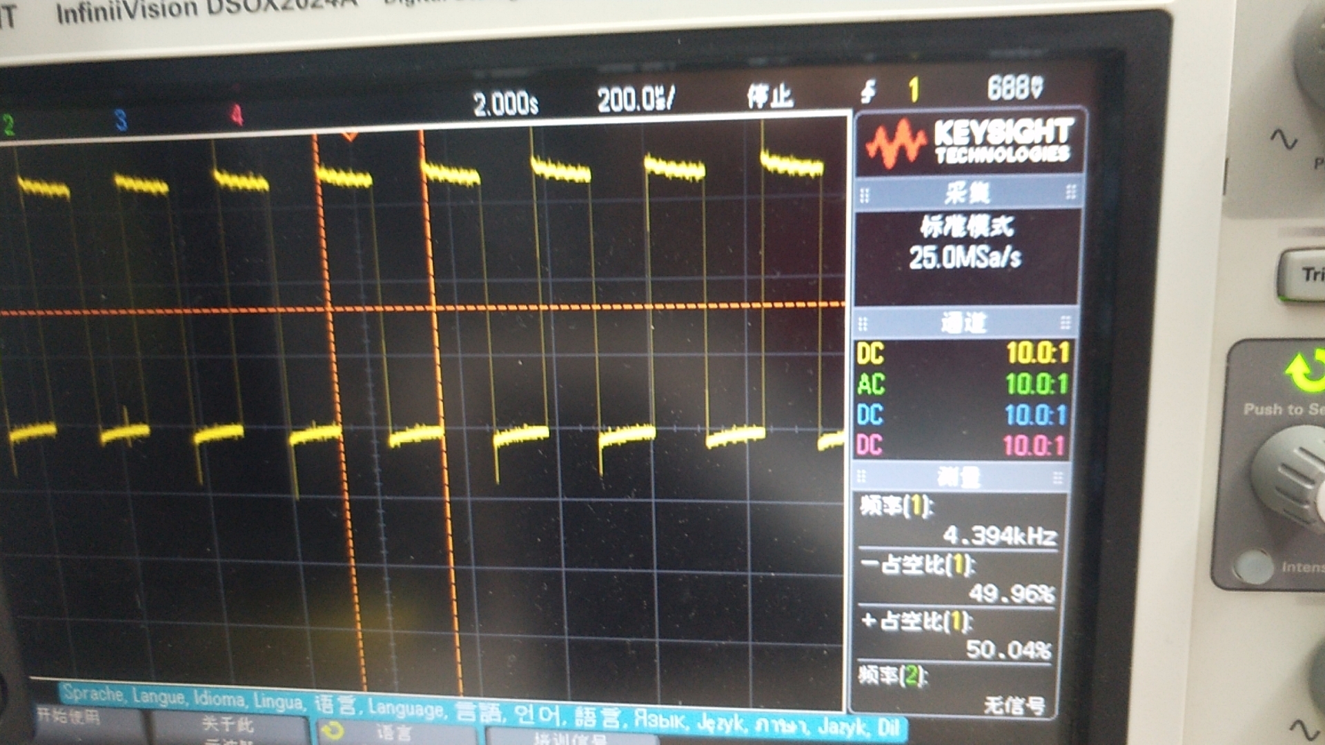
Here is the output pwm waveform