S32K14X-ADC learning notes
S32K14x includes two 12 bit ADC modules: ADC0 and ADC1; The S32K11x only contains a 12 bit ADC module: ADC0.
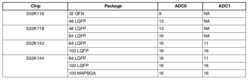
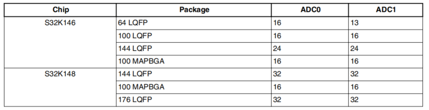
1. Number of ADC channels
Each ADC supports up to 32 external analog input channels, but the exact ADC channel number appearing on the device is different from the software package shown in the table below.
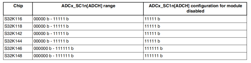
Adcx of chip_ The sc1n [adch] bit configuration conforms to the maximum channel configuration of the chip:
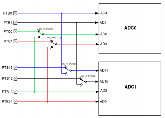
2. ADC hardware interleaving channel
The hardware interleaving on the device is realized as follows:
①,ADC0_4 and ADC1_14 channels staggered on PTB0;
②,ADC0_5 and ADC1_15 channels staggered on PTB1;
③,ADC0_8 and ADC1_8 channels staggered on PTB13;
④,ADC0_9 and ADC1_9 channels staggered on PTB14;
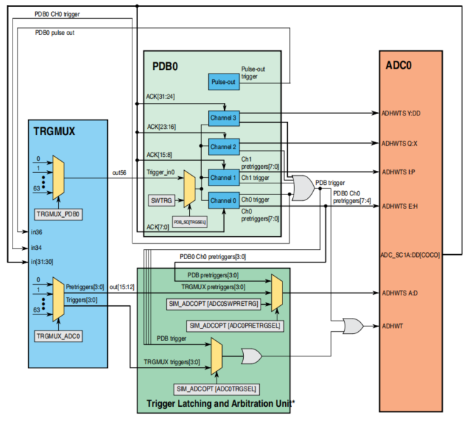
3. ADC trigger source
4. ADC characteristics
1. Linear continuous approximation algorithm, up to 12 bit resolution;
2. Up to 32 single ended external analog inputs;
3. Single ended 12 bit, 10 bit and 8-bit output modes;
4. Single ended output is output in right aligned format;
5. Single or continuous conversion mode;
6. Automatically restore to idle state after a single conversion;
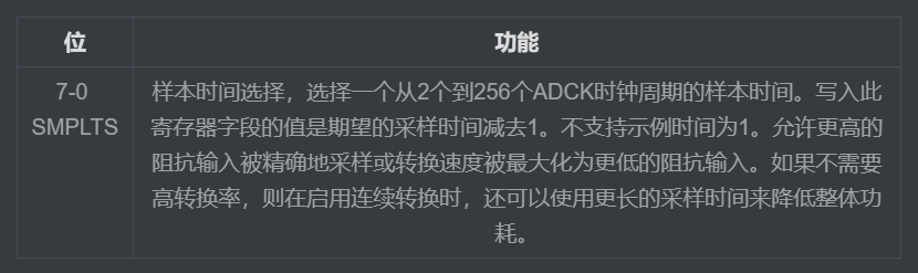
7. Configurable sampling time and conversion speed / power;
8. Flag and interrupt of conversion completion / hardware average completion;
9. The input clock can be selected from up to four sources;
10. Operate in low power mode to achieve low noise;
11. Hardware selection and switchable channel of trigger;
12. Automatically compare programmable values less than, greater than or equal to, within or out of range with interrupts;
13. Hardware averaging;
14. Optional voltage reference: external or standby;
15. Self calibration mode.
5. ADC memory mapping and register
5.1 memory mapping
ADC0 base address: 4003_B000h
ADC1 base address: 4002_7000h
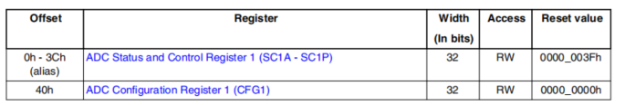
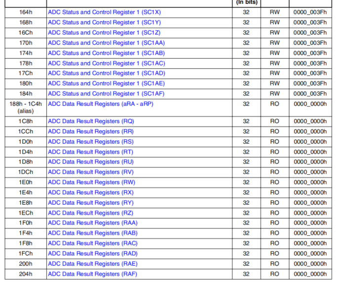
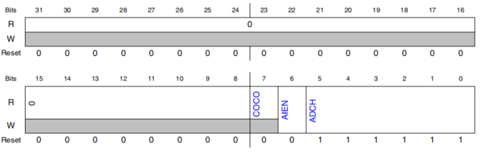
5.2 important registers
ADC status control register - SC1~SC3
Operation mode for software and hardware triggering.

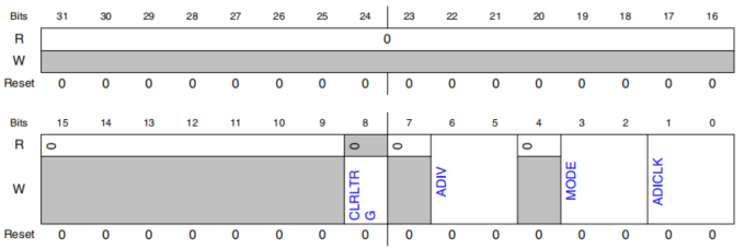
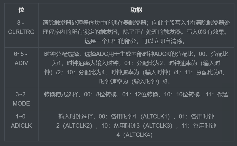
ADC configuration register - CFG1
Configuration register 1 (CFG1) is used to select operation mode, clock source and clock division.
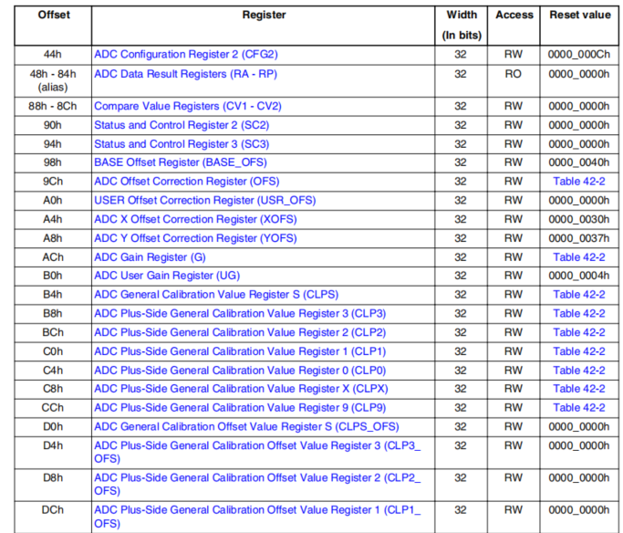
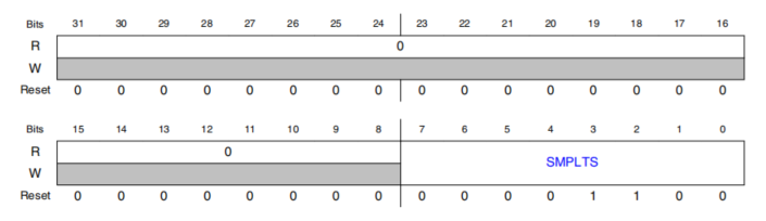
ADC configuration register-CFG2
6. ADC configuration process
adc.c Documents
#include "adc.h"


/******************************************************************************
  *Function: ADC_Init
  *Function: ADC module initialization
  *Parameters:
					nadc:  ADC Module ADC0, ADC1
					nbit:  adc resolving power
  *Return value: None
  *Remarks: None
  *******************************************************************************/
void ADC_Init(ADC_Type *base, ADC_nbit nbit)
{
	//Initialize ADC clock
	if(base == ADC0)
    {
        PCC->PCCn[PCC_ADC0_INDEX] &=~ PCC_PCCn_CGC_MASK;  /* Disable clock to change PCS */
        PCC->PCCn[PCC_ADC0_INDEX] |= PCC_PCCn_PCS(1);     /* PCS=1: Select SOSCDIV2      */
        PCC->PCCn[PCC_ADC0_INDEX] |= PCC_PCCn_CGC_MASK;   /* Enable bus clock in ADC     */
    }
    else
    {
        PCC->PCCn[PCC_ADC1_INDEX] &=~ PCC_PCCn_CGC_MASK;  /* Disable clock to change PCS */
        PCC->PCCn[PCC_ADC1_INDEX] |= PCC_PCCn_PCS(1);     /* PCS=1: Select SOSCDIV2      */
        PCC->PCCn[PCC_ADC1_INDEX] |= PCC_PCCn_CGC_MASK;   /* Enable bus clock in ADC     */
    }

	  base->SC1[0] =  ADC_SC1_ADCH(1) /* ADCH=1F: Module is disabled for conversions     */
                 |  ADC_SC1_AIEN(0);/* AIEN=0: Interrupts are disabled */
    base->CFG1 = ADC_CFG1_ADICLK(0) /* Only ALTCLK1 is available       */
               | ADC_CFG1_ADIV(0)   /* ADIV=0: Prescaler=1             */
               | ADC_CFG1_MODE(nbit);/* 0b00: 8-bit, 0b01: 12-bit, 0b10: 10-bit       */
    base->CFG2 = 0x00000000C;        /* SMPLTS=12(default): sample time is 13 ADC clks */
    base->SC2 = 0x00000000;          /* ADTRG=0: SW trigger                            */
                                     /* ACFE,ACFGT,ACREN=0: Compare func disabled      */
                                     /* DMAEN=0: DMA disabled                          */
                                     /* REFSEL=0: Voltage reference pins= VREFH, VREEFL*/
    base->SC3 = 0x00000000;          /* CAL=0: Do not start calibration sequence  */
                                     /* ADCO=0: One conversion performed          */
                                     /* AVGE,AVGS=0: HW average function disabled */

}


/******************************************************************************
  *Function: ADC_Read
  *Function: ADC acquisition once
  *Parameters:
						base:  ADC Module ADC0, ADC1
						chn :  adc passageway

  *Return value: ADC value (uint16#u T type)
  *Remarks: None
  *******************************************************************************/
uint16_t ADC_Read(ADC_Type *base, ADC_CH chn)
{
    uint16_t adc_result=0;

    base->SC1[0]&=~ADC_SC1_ADCH_MASK;	      /* Clear prior ADCH bits  */
    base->SC1[0] = ADC_SC1_ADCH(chn);         /* Initiate Conversion    */
    while(!((base->SC1[0] & ADC_SC1_COCO_MASK)>>ADC_SC1_COCO_SHIFT)); /* Wait for completion */
    adc_result = base->R[0];                  /* For SW trigger mode, R[0] is used */

  return  (uint16_t)(adc_result);             /* Convert result to mv for 0-5V range */

}


/******************************************************************************
*Function: ADC_Ave
*Power: ADC average filtering
*Parameters:
				nadc:  ADC Module ADC0, ADC1
				chn :  adc passageway
				N   :  Average filtering times

*Return value: ADC filter value
*Remarks: None
*******************************************************************************/
uint16_t ADC_Ave(ADC_Type *base, ADC_CH chn,uint16_t N)
{
    uint32_t tmp = 0;
    uint8_t  i;

    for(i = 0; i < N; i++)
    {
        tmp += ADC_Read(base, chn);
    }
    tmp = tmp / N;

    return (uint16_t)tmp;
}
adc.h file
#ifndef __ADC_H__
#define __ADC_H__

#include "S32K142.h" /* include peripheral declarations S32K144 */

typedef enum
{
  ADC_SE0=0,
  ADC_SE1=1,
  ADC_SE2=2,
  ADC_SE3=3,
  ADC_SE4=4,
  ADC_SE5=5,
  ADC_SE6=6,
  ADC_SE7=7,
  ADC_SE8=8,
  ADC_SE9=9,
  ADC_SE10=10,
  ADC_SE11=11,
  ADC_SE12=12,
  ADC_SE13=13,
  ADC_SE14=14,
  ADC_SE15=15,
}ADC_CH;

//Precision digit
typedef enum ADC_nbit
{
  ADC_8bit   = 0x00,
  ADC_10bit  = 0x02,
  ADC_12bit  = 0x01,
} ADC_nbit;


/******************************************************************************
  *Function: ADC_Init
  *Function: ADC module initialization
  *Parameters:
					nadc:  ADC Module ADC0, ADC1
					nbit:  adc resolving power
  *Return value: None
  *Remarks: None
  *******************************************************************************/
void ADC_Init(ADC_Type *base, ADC_nbit nbit);


/******************************************************************************
  *Function: ADC_Read
  *Function: ADC acquisition once
  *Parameters:
						base:  ADC Module ADC0, ADC1
						chn :  adc passageway

  *Return value: ADC value (uint16#u T type)
  *Remarks: None
  *******************************************************************************/
uint16_t ADC_Read(ADC_Type *base, ADC_CH chn);


/******************************************************************************
*Function: ADC_Ave
*Power: ADC average filtering
*Parameters:
				nadc:  ADC Module ADC0, ADC1
				chn :  adc passageway
				N   :  Average filtering times

*Return value: ADC filter value
*Remarks: None
*******************************************************************************/
uint16_t ADC_Ave(ADC_Type *base, ADC_CH chn,uint16_t N);

#endif
main.c Documents
#include "include.h"

//delayed
void delayms(int ms)
{
    volatile uint32_t i = 0;
	while(ms--)
	{
		for (i = 0; i < 10000; ++i)
		{
			__asm("NOP"); /* delay */
		}
	}
}


int main(void)
{


    SOSC_init_8MHz();	   /* Initialize system oscilator for 8 MHz xtal */
    SPLL_init_160MHz();	   /* Initialize SPLL to 160 MHz with 8 MHz SOSC */
    NormalRUNmode_80MHz(); /* Init clocks: 80 MHz sysclk & core, 40 MHz bus, 20 MHz flash */

		char txt[32];
    	uint16_t ADC_temp[8];

		ADC_Init(ADC1, ADC_12bit);                      //Initialize ADC1
		uartInit(UART0, 115200);

		ADC_temp[3] = ADC_Ave(ADC1, ADC_SE4 , 10); //PTC6
		printf("ptc6 : %5d \n", ADC_temp[3]);

	  ADC_temp[2] = ADC_Ave(ADC1, ADC_SE5 , 10); //PTC7
		printf("ptc7 : %5d \n", ADC_temp[2]);

	  while(1);
      return 0;
}
The project simulation and PCB project have been placed in the official account below, and can be concerned about the official account: Kevin learning station, enter the keyword: "S32K14X-DMA", you can get it free of charge! It's not easy to create, but your praise, attention and collection are my greatest encouragement!