Old routine; Introduction, pursue the source, and then talk about reality
When it comes to LEDs, everyone must be familiar. When playing the development board, we have lit patch LEDs of various colors, but when we need to use multiple LEDs at the same time, is the chip IO not enough? By the way, click my avatar to see the Charlie multiplexing algorithm. What if it's still not enough?
New props appeared - slightly expensive coding RGB-SK6812
Of course, there are more encoded LED s than this model, similar to WS2812B, but the control principle is the same. If you want to ask me why the principle is similar, it is not made by the manufacturer to replace other materials with higher prices. Let's get back to the point. Let's get familiar with the specific control principle first, as shown in the following figure;
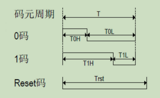
Information from the diagram:
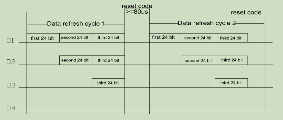
(1) Coding is to complete the RGB effect of an LED with 24bit, that is, if N LEDs need to be lit, N 24bit data need to be sent, and then reset to realize the effect of different colors of different LEDs
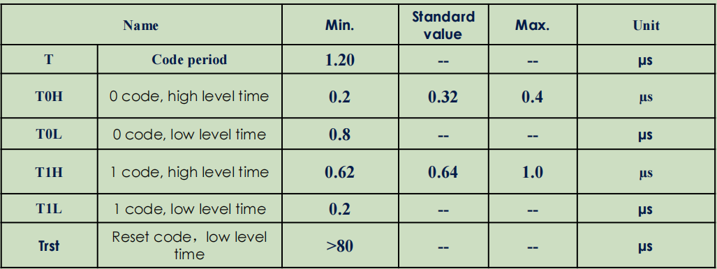
(2) High and low level of each bit: cycle = 1.2us, duty cycle = 50% is 1, duty cycle = 30% is 0
(3) Coded LED is single line communication. There are three methods that can be conceived here: 1-SPI; 2-IO; 3-PWM
Here I will not explain in detail the problems I encountered in actual operation and how I eliminated these methods. Finally, I chose PWM+DMA because this scheme does not waste resources, and has strong portability and operability
text
In the selection of MCU, confirm whether it has PWM+DMA function. If not, you can stop wasting time;
First, configure PWM. Here is a function. The MCU I use can register two PWM waveforms at the same time. Users need to confirm whether the MCU they use has this function or can register more PWM waveforms at the same time. Pre store the two waveforms during initialization;
pwm_set_cycle_and_duty(PWM_ID,(uint8_t)(RGB_cycle_set),(uint8_t)(RGB_duty_high_value));
pwm_set_pwm0_shadow_cycle_and_duty(RGB_cycle_rest_set,RGB_duty_rest_low_value);
/*The configuration of each MCU is different and no fine correction is required*/
Then preset the interrupt
	pwm_set_interrupt_enable(PWM_IRQ_PWM0_IR_DMA_FIFO_DONE);
	irq_set_mask(FLD_IRQ_SW_PWM_EN);
At this time, it is not necessary to turn on the PWM output until the PWM group to be output is configured in the main function;
The preparation work is not finished yet. We need to configure the drive functions of output high level and output low level at the underlying code separately
/*
 * @description		: Set pwm of level 1
 * @param - none 	: nothing
 * @return - none 	: nothing
 */
uint16_t hal_set_pwm0_high(void)
{
	return pwm_config_dma_fifo_waveform(1, PWM0_PULSE_NORMAL, 1);//High pulse effective, 1 PWM0_PULSE_NORMAL frame
}

/*
 * @description		: pwm setting level 0
 * @param - none 	: nothing
 * @return - none 	: nothing
 */
uint16_t hal_set_pwm0_low(void)
{
	return pwm_config_dma_fifo_waveform(1, PWM0_PULSE_SHADOW, 1);//High pulse effective, 1 PWM0_PULSE_SHADOW frame
}
(the content is modified according to the SDK package provided by your MCU)
Then start the formal driver:
/*
 * @description		: DMA is filled, and multiple rgb s in a single color gamut are bright
 * @param - len 	: Number of lights to display
 * @param - *rgb 	: Array of three color parameters of the lamp to be displayed
 * @return - none 	: nothing
 */
void api_SK6812_send_dat_one_in(uint8_t *rgb, uint16_t len)
{
	uint8_t i;
	uint8_t memaddr = 2;
	while (len)
	{
		for(i=0; i<8; i++) // GREEN data
	    {
			IR_DMA_Buff[memaddr] = ((rgb[GREEN]<<i) & 0x0080) ? hal_set_pwm0_high():hal_set_pwm0_low();
	        memaddr++;
	    }
	    for(i=0; i<8; i++) // RED
	    {
	    	IR_DMA_Buff[memaddr] = ((rgb[RED]<<i) & 0x0080) ? hal_set_pwm0_high():hal_set_pwm0_low();
	        memaddr++;
	    }
	    for(i=0; i<8; i++) // BLUE
	    {
	    	IR_DMA_Buff[memaddr] = ((rgb[BLUE]<<i) & 0x0080) ? hal_set_pwm0_high():hal_set_pwm0_low();
	        memaddr++;
	    }
	}

	uint32_t length = memaddr*2 - 4;
	uint16_t *buff ;
	buff=IR_DMA_Buff;
	buff[0]= length&0xff;
	buff[1]= (length>>16)&0xff;
	SK6812_Show();
}
This is a code driven by multiple LED s in a single color. In short, we use logic to fill our array data into the DMA array, and then drive the DMA. The same is true for the later functions. Then, we can change the contents of the array in the periphery to achieve various desired tasks, such as breathing, gradient and glare
Thought is such an idea. To realize the task, I suggest you try it yourself. If you really don't want to, you can get it from the code base of my article