[write before]
In 2021, the National College Students' electronic design competition was postponed because of the epidemic, which made people want to cry without tears. During the summer training, three control simulation problems were done, in which the PID control algorithm was used for the balance car and spherical car. Many strange problems were encountered in the debugging process. It has to be said that PID is so cruel to those who don't understand it, but it is a sharp weapon to those who master it. For me, I can't say that I have been able to use it skillfully. I just have a glimpse of the mystery. Now I summarize the experience gained in the process of blood and tears as follows.
The first item of contact with PID is the wind swing of the national tournament. At that time, the understanding of the meaning of the PID algorithm still remained on the surface. I was impressed that the final adjustment was not very good, and it could oscillate within a certain time and soon oscillated. The second PID project is to balance the trolley. PD and PI are used for the angle ring and speed ring respectively. The effect of angle ring adjustment is very good, but after adding the speed ring, the whole person was confused. The trolley began to oscillate at a large low frequency and couldn't stand up. At that time, I was very afraid. Because I was worried about the mechanical structure of the trolley, I didn't dare to increase the speed ring. Now I think it's stupid (equivalent to insufficient damping effect).
[commissioning experience]
Generally speaking, the parameter setting is in the following order:
1.KP setting
-
Generally, first adjust P and set other parameters to zero to determine the polarity of P, and then increase P from small to large until equal amplitude oscillation occurs in the system.
-
Increasing P will increase the system response speed, but too large P will make the system unstable and have large errors
2.KI setting
-
The adjustment function of the integration link is to eliminate the static error. The greater the integration constant Ti, the weaker the accumulation function of the integration (I don't understand it at first, but it can be explained as
The greater the integration constant, the fewer the cumulative times, and the upper limit will be reached by accumulating several times).
-
Increasing I can prevent the system from oscillation during transition, reduce overshoot and improve the stability of the system, but it will slow down the elimination process of static error.
3.KD setting
-
The function of differential is to make the system * * give appropriate correction in advance according to the variation trend of deviation * *, which will help to reduce overshoot, overcome oscillation and make the system more stable
It is very stable, especially for high-order systems. It speeds up the tracking speed of the system.
-
The function of differentiation is very sensitive to the noise of the input signal. For those systems with large noise, differentiation is generally not needed, or the input signal is filtered before differentiation works.
Small summary
Summarize with a table:
| arrange mode | rise time | Overshoot | Settling time | steady-state error | stability |
|---|---|---|---|---|---|
| KP increase | reduce | increase | Slight increase | reduce | Variation |
| KI increase | Slight decrease | increase | increase | Substantial reduction | Variation |
| KD increase | Slight decrease | reduce | reduce | Basically unchanged | Get better |
In addition, the following points should be noted:
- When setting parameters individually, it must be noted that the polarity of each parameter must be correct, and the judgment standard is the above table.
- According to engineering experience, the relationship between KP and KI is KP=KI * 200. Of course, the formula is dead and should be adjusted according to the actual situation.
[position PID]
1. Formula
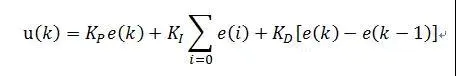
Position PID is the deviation between the actual position of the current system and the expected position you want to achieve. PID control is carried out. The current output u(k) is related to all States in the past
u(k) corresponds to the actual position of the actuator.
2. Precautions
1. Integral limiting and output limiting shall be added
2. It is applicable to objects without integral parts of the actuator, such as the erection of steering gear and balance trolley, the control of temperature control system, automatic line inspection, etc
3. Typical code
typedef struct
{
  float Kp;                       //Proportional coefficient
  float Ki;                       //Integral coefficient
  float Kd;                       //Differential coefficient

  float Ek;                       //Current error
  float Ek1;                      //Previous error e(k-1)
  float Ek2;                      //Re previous error e(k-2)
  float LocSum;                   //Cumulative integral position
}PID_LocTypeDef;

float PID_Loc(float SetValue, float ActualValue, PID_LocTypeDef *PID)
{
  float PIDLoc;                                  //position

  PID->Ek = SetValue - ActualValue;
  PID->LocSum += PID->Ek;                         //Cumulative error

  PIDLoc = PID->Kp * PID->Ek + (PID->Ki * PID->LocSum) + PID->Kd * (PID->Ek1 - PID->Ek);

  PID->Ek1 = PID->Ek;  return PIDLoc;
}
[incremental PID]
1. Formula
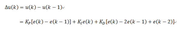
Control increment Δ The determination of u(k) is only related to the last three sampling values. It is to take the increment of the position PID. At this time, the output of the controller is the sum of the position values calculated at the two adjacent sampling times
Poor, the result is increment, that is, the control amount needs to be increased (negative value means reduction) on the basis of the last control amount. It is easy to obtain a better control effect through weighting processing, and
In case of system problems, incremental will not seriously affect the work of the system.
2. Precautions
1. Applicable to objects with integral parts of actuator, such as stepping motor, etc
2. Incremental PID only needs to output limiting
3. Typical code
typedef struct
{
  float Kp;                       //Proportional coefficient
  float Ki;                       //Integral coefficient
  float Kd;                       //Differential coefficient

  float Ek;                       //Current error
  float Ek1;                      //Previous error e(k-1)
  float Ek2;                      //Re previous error e(k-2)
}PID_IncTypeDef;


float PID_Inc(float SetValue, float ActualValue, PID_IncTypeDef *PID)
{
  float PIDInc;                                  //increment

  PID->Ek = SetValue - ActualValue;
  PIDInc = (PID->Kp * PID->Ek) - (PID->Ki * PID->Ek1) + (PID->Kd * PID->Ek2);

  PID->Ek2 = PID->Ek1;
  PID->Ek1 = PID->Ek;  return PIDInc;
}