catalogue
1. Car end camera and wifi initialization
three The car takes pictures and transmits images
4. Raspberry sends back the control command to the esp32 trolley
Recently, we want to develop a picture transmission car. First, use the simplest and easiest hardware, esp32cam from AI thinker, as the image acquisition and sending end, and use raspberry pie to receive and display.
The car end uses esp32cam. This module is very easy to use. It integrates wifi and camera. The initial wifi performance is good. The 480x320p image is transmitted smoothly in the office environment. Occasionally, it gets stuck because it is blocked by the cement wall.
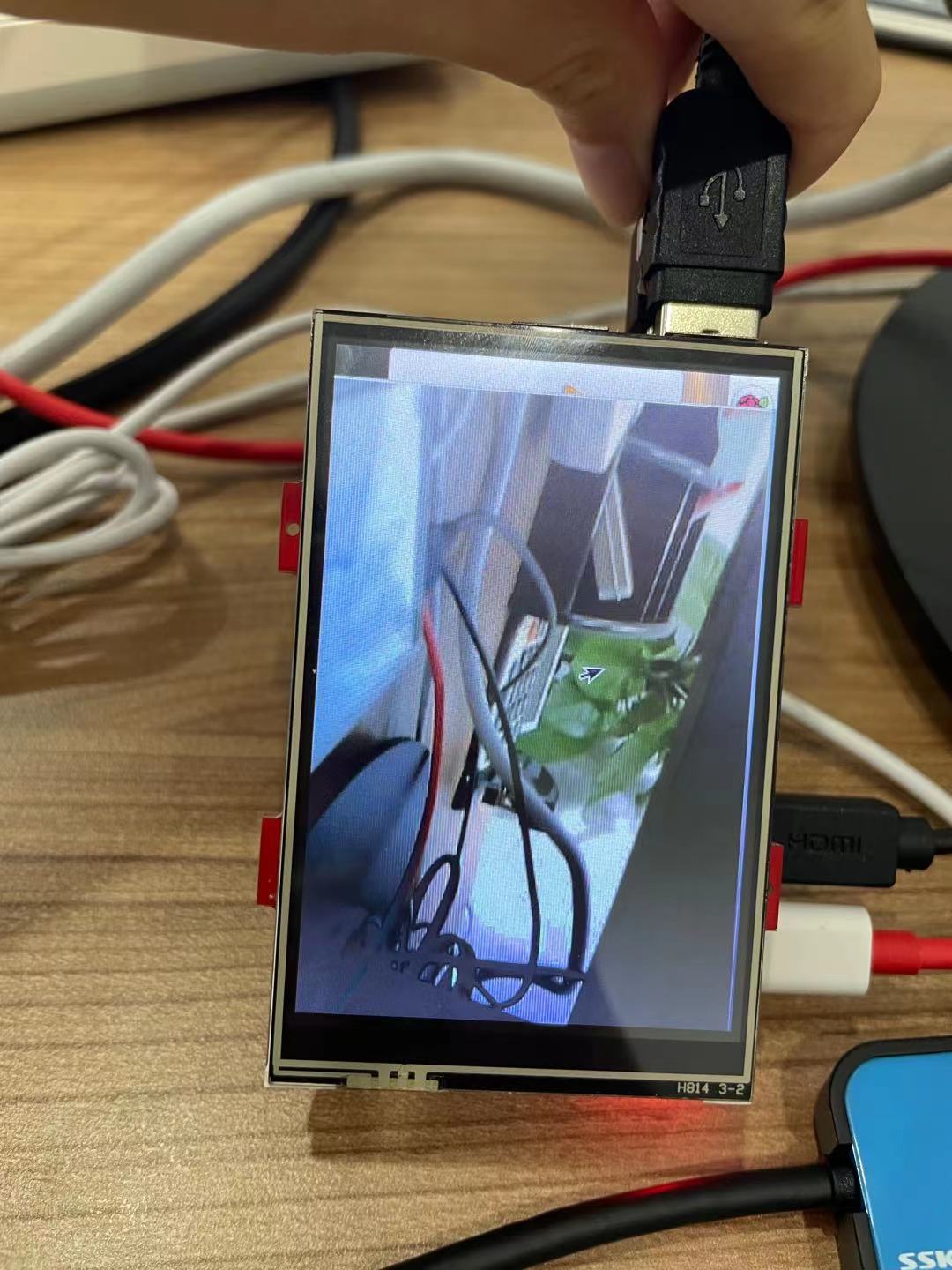
The receiver uses raspberry pie 4B and a 3.5-inch GPIO screen. This should be the SPI interface of the LCD screen. The refresh rate is basically one frame per second. The subsequent HDMI screen should be better. But at least the system is set up and recorded in this document. The main procedure is as follows:
#include <WiFi.h>
#include "esp32_car.h"

void Camera_Initialization ();
void Wifi_setup();
void Streaming();

void setup() {

  Serial.begin(115200);
  Serial.setDebugOutput(true);
  delay(1000);

  Camera_Initialization ();
  Wifi_setup();
  Streaming();
}

void loop() {
}
The specific implementation is divided into the following parts:
1. Car end camera and wifi initialization
Here we use the ov2640 camera of esp32cam, with average performance. Xiaobai, I'd better choose the camera (short cable) provided by AI Thinker official, because we replaced an ov2640 camera of the same model with a cable length of 7.5cm, and there were all kinds of inexplicable errors, such as
- camera: Timeout waiting for VSYNC
- SCCB_Write(): SCCB_Write Failed addr:0x30, reg:0xe1, data:0x67, ret:263
I found relevant error reports on the Internet, basically saying that the quality of my camera is too poor. It is recommended to change back to the official camera. But in fact, the root cause of these errors is
- The amount of data is too large (the QVGA resolution used in the routine is too high);
- The camera frequency is too high (XCLK defaults to 20MHz);
- The mainboard cannot carry such a long cable (the loss of the signal after transmission through too long cable is too large to reach the required level threshold).
Knowing this, we have a clue to solve it. It's nothing more than reducing the camera resolution frame_size, and reduce the camera clock frequency xclk_freq_hz. According to our experimental results, one of the parameters can be reduced. The parameter of clock frequency xclk is more subtle, and we can only test it to 5MHz at the lowest.
config.frame_size = FRAMESIZE_HVGA;
config.xclk_freq_hz = 10000000;
During the experimental test, we will still observe the two problems mentioned earlier (VSYNC and SBBC). In order to improve the reliability of the program, we added a piece of code. If the camera initialization is unsuccessful, restart the system in one second.
while (esp_camera_init(&config) != ESP_OK) {
    Serial.println("Camera initalization failed");
    esp_deep_sleep(1000000); // Restart after 1 second
  }
Camera initialization is over, and the next step is to initialize wifi. The reason is very simple. It is to create an AP hotspot wifi, named esp32cam, and then let the raspberry pie terminal connect to this wifi.
2. Create a UDP connection
The car end creates a UDP connection through the udp.begin function. You need to know the car IP (because we created AP wifi for the car before, the default IP is 192.168.4.1) and the car port number CAR_UDP_PORT (we use macros to define it as 1122). In other words, we know the IP and port number of the car in advance, but we don't know the IP address of raspberry pie.
// Start a udp service
  udp.begin(myIP, CAR_UDP_PORT);
If we want to send data to raspberry pie, we must automatically obtain the IP of raspberry pie. This requires the raspberry pie to send a message like the car's IP and port after connecting to the car's wifi, so that the car can know the raspberry pie's IP by listening to the port number. udp.remoteIP() and udp.remotePort() are called here. The specific implementation is as follows:
// Once the controller sends a string to me and then I can get his IP
void GetRemoteIP() {

  uint8_t rBuff[256]; //UDP receive buffer

  // Listen at "CAR_UDP_PORT"
  while (1) {

    // Check to see if UDP packet has come to me
    int len = udp.parsePacket();

    if (len > 0)
    {
      // Read the incoming string to rBuff
      len = udp.read(rBuff, len);
      Serial.write(rBuff, len);

      //Get remote ip
      toAddress = udp.remoteIP();
      toPort = udp.remotePort();
      Serial.print("\n Remote IP address: ");
      Serial.print(toAddress);
      Serial.printf(":%d\n", toPort);

      break;
    }
  }
}
Correspondingly, the raspberry pie end needs to send a message to the car to let the car monitor. Before sending, raspberry pie first needs to know its own IP address. This can be obtained by establishing a new socket to any legal IP address (it doesn't matter whether it can be ping ed, such as 8.8.8.8) and according to the returned getsockname() function. Then the raspberry pie binds its own IP to a socket usoc. Note that the socket s here is only created to get the IP address of raspberry pie; The socket really used to communicate with esp32cam is the usoc used to send messages later.
import socket

# Get wlan0 IP address
s = socket.socket(socket.AF_INET, socket.SOCK_DGRAM)
s.connect(("8.8.8.8", 80))
IP_controller = (s.getsockname()[0])
print(IP_controller)
s.close()

usoc = socket.socket(socket.AF_INET, socket.SOCK_DGRAM) #UDP socket
usoc.bind((IP_controller, 6000)) #IP & port

# Send a message to car in order for car to get my IP
usoc.sendto(b'from pi', ('192.168.4.1', 1122))
three The car takes pictures and transmits images
The code of the car mainly refers to the tutorial of CameraWebServer in the official routine and Daniel UP master "technical house story" in station B ESP32 and Python realize wireless video transmission, and the technology is open source.
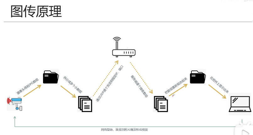
The general idea is to use esp32 to start a UDP service, make the pictures collected by the camera frame by frame into UDP packets and send them to the raspberry pie end of the remote control. After receiving the UDP packet, the raspberry pie will restore the pictures frame by frame, and then display them with opencv. The UP master in the reference video mentioned that he didn't use esp32cam because there were some problems with the camera. In fact, he forgot to call esp after sending the picture_ camera_ fb_ Return (FB) to clear the camera cache. The code implementation is compatible with esp32cam.
// Take a picture and UDP send to remote port
void Streaming() {

  camera_fb_t * fb = NULL;
  esp_err_t res = ESP_OK;
  uint8_t rBuff[256]; //UDP receive buffer

  // Start a udp service
  udp.begin(myIP, CAR_UDP_PORT);

  // Get remote controller IP address
  GetRemoteIP();

  int fid = 0; // Frame ID
  while (1)
  {
    // Capture a picture
    fb = esp_camera_fb_get();

    // Send the image
    if (fb)
    {
      udp_send_chunk((uint8_t *)fb->buf, fb->len, ++fid);
      esp_camera_fb_return(fb);
      fb = NULL;
    }
    //    delay(100);
  }
}
The raspberry pie terminal uses opencv to convert the obtained frame into jpg and display it on the LCD screen. The driving reference of LCD screen is here: 3.5inch RPi Display - LCD wiki
nparr = np.frombuffer(jpgBuff, dtype=np.uint8)
image = cv2.imdecode(nparr, cv2.IMREAD_COLOR)
cv2.imshow('ESP',image)
Sometimes, python 3 will report an error and cannot import the CV2 library. You can refer to this post Raspberry pie Python 3 installation cv2_ Raspberry pie 3b uses pip and apt to install Python 3 opencv_ weixin_ 39594312 blog - CSDN blog
To install. The specific methods are summarized as follows:
sudo apt-get install python3-numpy
Sudo pip3 install opencv-python
Sudo apt-get install libatlas-base-dev
Sudo pip3 install numpy --upgrade
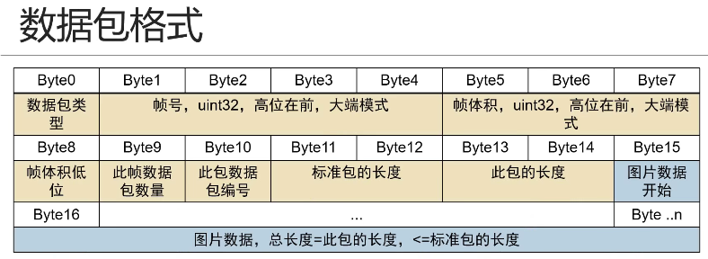
With the framework of "picture transmission", we can officially use UDP transmission. According to the figure below, the frame captured by the camera is packaged into a UDP packet at the trolley end, where the packet length is packetlen=1000. Note that in order to make the program look simpler, we do not use the above "high order first" method to store the quantities of "frame number, frame volume, standard packet length and this packet length"; Instead, we directly use the memcpy function to write these parameters into the packet header using the "low order first" method.
void udp_send_chunk(uint8_t* frame, size_t len, size_t frameCount)
{
  uint8_t txBuffer[1024] = {0};
  size_t frameId = frameCount;
  size_t frameSize = len;

  int packetCount = 0;
  int packetId = 1;
  int packetLen = 1000;
  int packetSize = 0;

  if (frameSize == 0)
  {
    Serial.printf("Send buffer len=0.\r\n");
    return;
  }

  packetCount = frameSize / packetLen + ((frameSize % packetLen) == 0 ? 0 : 1);

  size_t sendOffset = 0;
  while (sendOffset < frameSize)
  {

    packetSize = ((sendOffset + packetLen) > frameSize) ? (frameSize - sendOffset) : (packetLen);

    //Header
    txBuffer[0] = 0x12;
    memcpy(&txBuffer[1], &frameId, 4);
    memcpy(&txBuffer[5], &frameSize, 4);
    txBuffer[9] = packetCount;
    txBuffer[10] = packetId;
    memcpy(&txBuffer[11], &packetLen, 2);
    memcpy(&txBuffer[13], &packetSize, 2);

    // Data
    memcpy(&txBuffer[15], frame + sendOffset, packetSize);

    //UDP send packet
    udp.beginPacket(toAddress, toPort);
    udp.write((const  uint8_t *)txBuffer, 15 + packetSize);
    udp.endPacket();

    //Set send offset to next position
    sendOffset += packetSize;
    packetId++;
  }
}
Correspondingly, the raspberry pie end needs to splice the received package into a frame image.
    udpbuff, address = usoc.recvfrom(10240)

	frameId = (udpbuff[4] << 24) + (udpbuff[3] << 16) + (udpbuff[2] << 8) + udpbuff[1]
	frameSize = (udpbuff[8] << 24) + (udpbuff[7] << 16) + (udpbuff[6] << 8) + udpbuff[5]
	packetId = udpbuff[10]
	packetSize = (udpbuff[14] << 8) + udpbuff[13]

	if frameIdNow != frameId:
		frameIdNow = frameId
		frameSizeNow = frameSize
		packetCount = udpbuff[9]
		packetLen = (udpbuff[12] << 8) + udpbuff[11]
		frameSizeOk = 0
		packetIdNow = 0
		jpgBuff = bytes('', 'utf-8')

	if (packetId <= packetCount) and (packetId > packetIdNow):
		if packetSize == (len(udpbuff)-15):
			if (packetSize == packetLen) or (packetId == packetCount):
				jpgBuff = jpgBuff + udpbuff[15:]
				frameSizeOk = frameSizeOk + len(udpbuff) - 15
4. Raspberry sends back the control command to the esp32 trolley
In fact, we can listen to the udp receive buffer in the while loop where the car sends pictures frame by frame, so as to accept the instructions sent by raspberries. If the "F" command sent by raspberry is received, the esp32 car will print "Car moving forward" to the serial port. In addition, raspberry pie can also regularly send "heartbeat" heartbeat information to the car end, so that the car end can always clarify the network situation, check whether the raspberry pie remote control is disconnected, and then carry out some processing such as emergency stop. The specific implementation of raspberry pie end is as follows:
usoc.sendto(b'heartbeat', ('192.168.4.1', 1122))The specific realization of the trolley end is as follows:
    int len = udp.parsePacket();
    if (len > 0)
    {
      len = udp.read(rBuff, len);
      //      Serial.write(rBuff, len);

      char rBuff_short[len + 1] = {0};
      strncpy(rBuff_short, (char *)rBuff, len);
      rBuff_short[len + 1] = '\0';

      if (!strcmp(rBuff_short, "heartbeat")) {
        Serial.print("heartbeat ");
      }

      if (!strcmp(rBuff_short, "F")) {
        Serial.print("Car moving forward!");
      }

      if (!strcmp(rBuff_short, "q")) {
        Serial.println("End streaming");
        break;
      }
    }