1) Experimental platform: punctual atom alpha Linux development board
2) Platform purchase address: https://item.taobao.com/item.htm?id=603672744434
2) Full set of experimental source code + manual + video download address: http://www.openedv.com/thread-300792-1-1.html
3) Students interested in punctual atomic Linux can add group discussion: 935446741
4) pay attention to the official account of the dot atom and get updated information.

Chapter 69 Linux Network Driver experiment
Network driver is linux One of the big three, linux The network function under is very powerful and embedded linux Network functions are also often used in. We have already talked about character device driver and block device driver. Let's learn this chapter linux Inside the network device driver.
69.1 introduction to embedded network
69.1.1 network hardware interface under embedded system
This chapter discusses all wired networks!
When it comes to the network, the hardware we generally think of is the "network card". The concept of "network card" was first spread from the computer field. As the name suggests, it is a card that can access the Internet. In the "primitive society" in the computer field, the network card is independent hardware. If the computer wants to surf the Internet, it has to buy a network card and plug it in, similar to the current graphics card. However, if you look at your notebook or desktop motherboard, you will find that there is no network card device similar to the graphics card. The reason is that with the continuous development of technology, only one chip is needed to realize the wired network card function, so the network card chips are directly placed on the motherboard. Therefore, when you contact the embedded system, when you hear the word "network card", don't rush to find something like "card" on the development board.
Now that the network card is completed through a chip, what kind of chip is it? We must first understand the network hardware scheme in embedded system. Firstly, the embedded network hardware is divided into two parts: MAC and PHY. Everyone judges whether an SOC supports the network by looking at the data manual. If a chip data manual says that it supports the network, it generally means that the SOC has a built-in Mac, which is similar to the peripherals like I2C controller and SPI controller. However, MAC alone can not directly drive the network, and another chip is needed: PHY. Therefore, for the SOC with built-in Mac, a PHY chip must be matched externally. However, some SOCS have no Mac, so they can't match PHY chips. How can these chips without network MAC access the Internet? Here we will involve two common embedded network hardware solutions.
1. There are no network MAC peripherals in SOC
Generally speaking, an SOC does not support network, that is, it does not have network MAC. So this chip can't access the Internet? Obviously not. Since there is no internal Mac, you can find an external MAC chip, but generally this external network chip is integrated with MAC+PHY. For example, the DM9000 used most in Samsung's linux development board. Because Samsung's chip basically has no internal MAC (such as S3C2440, S5PV2104412, etc.), Samsung's development board completes the wired network function through the external DM9000. The DM9000 provides an SRAM interface to the SOC, and the SOC will operate the DM9000 in the way of SRAM.
Some external network chips are more powerful. They even integrate a hardware TCP/IP protocol stack to provide an SPI interface, such as W5500. This is generally used in the field of single chip microcomputer. Single chip microcomputer communicates with W5500 through SPI interface. Because W5500 has built-in hardware TCP/IP protocol stack, single chip microcomputer does not need to transplant the responsible software protocol stack. It operates W5500 directly through SPI, which simplifies the networking scheme of single chip microcomputer.
The advantage of this scheme is that the SOC that does not support the network can find another way to realize the network function, but the disadvantage is that the network efficiency is not high, because the MAC built in the general chip will have a network acceleration engine, such as network dedicated DMA, and the network processing efficiency will be very high. Moreover, the network speed of such chips is not fast, which is basically 10/100M. In addition, compared with PHY chips, the cost of such chips is also relatively high and there are few choices.
The connection between SOC and external MAC+PHY chip is shown in figure 69.1.1.1:
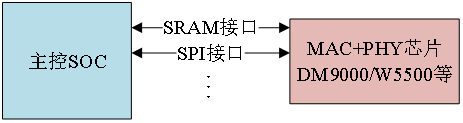
Figure 69.1.1.1 connection between main control SOC and external MAC+PHY chip
2. SOC internal integrated network MAC peripherals
We generally say that an SOC supports the network, that is, it integrates network MAC peripherals internally. At this time, we also need to connect an external network PHY chip. At this point, some friends will have questions. Can't PHY chip be integrated into SOC? The author has not seen the SOC that integrates PHY into the chip.
Generally, common general SOC will integrate network MAC peripherals, such as STM32F4/F7/H7 series and NXP I.MX series. The advantages of internal integrated network MAC are as follows:
① Internal MAC peripherals will have dedicated acceleration modules, such as dedicated DMA, to accelerate the processing of network speed data.
② The network speed is fast, and can support 10/100/1000M network speed.
③ . the external PHY has many options and low cost.
The internal MAC peripherals will be connected to the external PHY chip through MII or RMII interface, which is used to transmit network data. In addition, the master controller needs to configure or read the PHY chip, that is, read and write the internal register of phy, so it also needs a control interface called MIDO. MDIO is very similar to IIC. It is also two lines, one data line is called MDIO, and the other clock line is called MDC.
The connection between SOC internal MAC peripheral and external PHY chip is shown in figure 69.1.1.2:
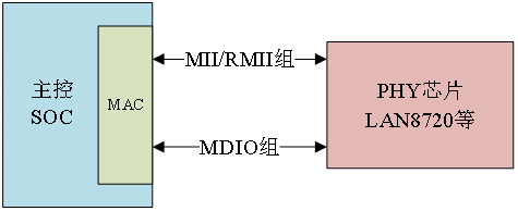
Figure 69.1.1.2 connection between internal MAC and external PHY
If you want to use the network function when you are doing the project, it is strongly recommended that you choose the master SOC with network MAC peripherals! 1. Mx6ull has two 10M/100M network MAC peripherals, and the punctual atom ALPHA development board carries two PHY chips, the model is LAN8720. Therefore, this chapter only explains the scheme of SOC internal MAC + external PHY chip.
69.1.2 MII/RMII interface
As we said earlier, the internal MAC connects with the external PHY chip through the MII/RMII interface to complete network data transmission. In this section, we will learn what MII and RMII interfaces are.
1. MII interface
The full name of MII is Media Independent Interface, which translates directly to Media Independent Interface. It is the Ethernet standard interface defined by IEEE-802.3. MII interface is used to connect Ethernet MAC to PHY chip. The connection diagram is shown in figure 69.1.2.1:
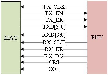
Figure 69.1.2.1 MII interface
MII interface has 16 signal lines in total, with the following meanings:
TX_CLK: transmit clock. If the network speed is 100M, the clock frequency is 25MHz, and if the network speed is 10M, the clock frequency is 2.5MHz. At this time, the clock is generated by PHY and sent to MAC.
TX_EN: send enable signal.
TX_ER: send error signal, high level is valid, indicating TX_ The data transmitted during the ER validity period is invalid. TX at 10Mpbs network speed_ Er does not work.
TXD[3:0]: 4 data signal lines in total.
RXD[3:0]: receive 4 data signal lines in total.
RX_CLK: receive the clock signal. If the network speed is 100M, the clock frequency is 25MHz; if the network speed is 10M, the clock frequency is 2.5MHz, RX_CLK is also generated by PHY.
RX_ER: receive error signal, high level is valid, indicating Rx_ The data transmitted during the ER validity period is invalid. RX at 10Mpbs network speed_ Er does not work.
RX_DV: valid received data, similar to TX_EN.
CRS: carrier sense signal.
COL: conflict detection signal.
The disadvantage of MII interface is that too many signal lines are required, which does not include the data lines of MDIO and MDC management interfaces. Therefore, MII interface has been used less and less.
2. RMII interface
The full name of RMII is Reduced Media Independent Interface, which translates into a simplified media independent interface, that is, a simplified version of MII interface. RMII interface only needs 7 data lines, which is directly reduced by 9 compared with MII, which greatly facilitates board wiring. The schematic diagram of RMII interface connecting PHY chip is shown in figure 69.1.2.2:
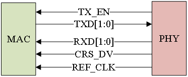
Figure 69.1.2.1 RMII interface
TX_EN: send enable signal.
TXD[1:0]: 2 data signal lines in total.
RXD[1:0]: receive 2 data signal lines in total.
CRS_DV: equivalent to Rx in MII interface_ Mixing of DV and CRS signals.
REF_CLK: reference clock, provided by external clock source, with frequency of 50MHz. Here, unlike MII, the receiving and transmitting clocks of MII are independent and provided by PHY chip.
In addition to MII and RMII, there are other interfaces, such as GMII, RGMII, SMII, SMII, etc. other interfaces are basically the same, so I won't explain them here. The two network ports on the punctual atom ALPAH development board use RMII interface to connect MAC and external PHY chip.
69.1.3 MDIO interface
The full name of MDIO is Management Data Input/Output, which translates to Management Data Input/Output interface. It is a simple two-wire serial interface, an MDIO data line and an MDC clock line. The driver can access any register of phy chip through MDIO and MDC lines. The MDIO interface supports up to 32 Phys. Only one PHY can be operated at the same time, so how to distinguish these 32 PHY chips? Just like IIC, use the device address. The device addresses of all PHY chips under the same MDIO interface cannot conflict and must be unique. For specific device address values, please refer to the corresponding PHY data manual.
Therefore, MII/RMII and MDIO interfaces are mainly used when connecting MAC and external PHY chips. In addition, reset, interrupt and other pins may be required.
69.1.4 RJ45 interface
Network equipment is connected through network cable. RJ45 seat is inserted into the network cable, as shown in figure 69.1.4.1:
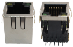
Figure 69.1.4.1 RJ45 seat
RJ45 block shall be connected with PHY chip, but a network transformer is required in the middle. The network transformer is used for isolation and filtering. The network transformer is also a chip, and its shape is generally shown in figure 69.1.4.2:
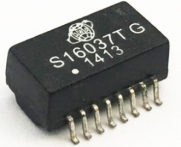
Figure 69.1.4.2 network transformer
However, many RJ45 seats have integrated network transformers. For example, HR911105A used by punctual atom ALPHA development board is RJ45 seats with built-in network transformers. The RJ45 seat with built-in network transformer is the same as the pin without built-in, but generally, the RJ45 seat without built-in will be shorter. Therefore, when drawing the board, you must consider whether the RJ45 seat you use has a built-in network transformer. If not, you must add some circuits of the network transformer by yourself!!! Similarly, if the hardware you design needs RJ45 seats with built-in network transformer, you must not weld an RJ45 seat without built-in transformer, otherwise the network will not work normally!
There are generally two lights on RJ45 seat, one yellow (Orange) and one green. If green is on, it indicates that the network connection is normal, and if yellow flashes, it indicates that network communication is currently in progress. The two lights are controlled by the PHY chip. The PHY chip will have two pins to connect the two lights on the RJ45 base. Internal MAC + external PHY+RJ45 (built-in network transformer) constitute a complete embedded network interface hardware, as shown in figure 69.1.4.2:
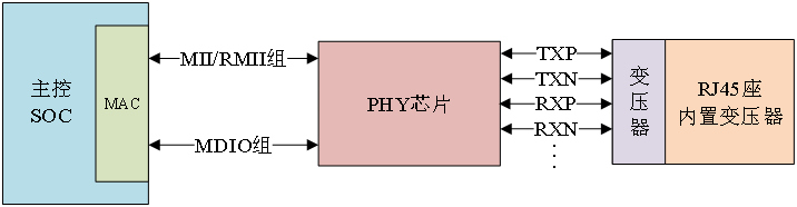
Figure 69.1.4.2 schematic diagram of embedded network hardware interface
69.1.5 introduction to i.mx6ull eNet interface
1. Mx6ull has two network interfaces, that is, two MAC peripherals. One MAC is connected to a PHY chip to form a complete network interface. In this section, we briefly learn about the ENET interface of I.MX6ULL. 1. The built-in ENET peripheral of mx6ull is actually a network MAC, supporting 10/100M. Three layer network acceleration is realized to accelerate those general network protocols, such as IP, TCP, UDP and ICMP, and provide acceleration services for client applications.
1. Mx6ull core integrates two 10/100Mbit/S network Macs, which comply with IEEE802.3-2002 standard. The MAC layer supports duplex and half duplex LAN. Mac is programmable and can be used as NIC card or some other switching devices. According to IETF RFC 2819 protocol, MAC implements RMON(Remote Network Monitoring) counting function. The MAC kernel has a hardware acceleration processing unit to improve network performance. The hardware acceleration unit is used to process TCP/IP, UDP, ICMP and other protocols. The effect of processing frame header information by hardware is much better than that by a lot of software. ENET peripheral has a dedicated DMA, which is used to transfer data between ENET peripheral and SOC, and supports programmable enhanced buffer descriptor to support IEEE 1588.
1. The main features of mx6ull internal ENET peripherals are as follows:
1) It realizes the full function of 802.3 specification preamble / SFD generation, frame filling, CRC generation and check.
2) . zero length preamble is supported.
3) Support 10/100M dynamic configuration.
4) . magic frame interrupt detection compatible with AMD remote node power management.
5) . the PHY chip can be seamlessly connected through the following interfaces:
·4-bit MII interface with frequency of 2.5/25MHz.
·The 4-bit MII Lite interface, that is, the MII interface cancels the CRS and COL lines, and the frequency is also 2.5/25MHz.
·2-bit RMII interface with a frequency of 50MHz.
6) The MAC address is programmable.
7) , multicast and unicast address filtering to reduce the processing burden of higher layers.
8) MDIO main interface is used to manage and configure PHY equipment.
......
1. There are many contents of ENET peripherals in mx6ull. For detailed introduction, please refer to the chapter "Chapter 22 10 / 100 Mbps Ethernet MAC (ENET)" in I.MX6ULL reference manual. When writing drivers, we don't need to pay attention to the specific contents of ENET peripherals, because these drivers are written by SOC manufacturers. We focus on where to adjust after replacing PHY chips.
69.2 detailed explanation of phy chip
69.2.1 introduction to basic knowledge of Phy
PHY is a standard module specified in IEEE 802.3. As mentioned earlier, SOC can configure PHY or read PHY related status, which requires PHY internal registers. The address space of phy chip register is 5 bits, and there are 32 registers at address 031. IEEE defines the functions of the 16 registers of 015, and the 16 registers of 1631 are implemented by the manufacturer. That is to say as like as two peas, the 015 PHY registers are exactly the same as those of the 16 chips you use. These 16 registers alone can completely drive the PHY chip and at least ensure the basic network data communication. Therefore, the Linux kernel has a general PHY driver. In principle, no matter which manufacturer's PHY chip you use, you can use the general PHY driver of Linux to verify whether the network works normally. In fact, some other problems may be encountered in the actual development, resulting in the abnormal operation of the general PHY driver of the Linux kernel. At this time, the driver developers need to debug. However, with the increasing performance of phy chips, 32 registers may not meet the needs of manufacturers. Therefore, many manufacturers use paging technology to expand the register address space in order to define more registers. These extra registers can be used to realize some technologies unique to the manufacturer, so the general PHY driver of the Linux kernel cannot drive these characteristic functions. At this time, the PHY manufacturer needs to provide the corresponding driver source code, so you will also see many specific PHY chip driver source codes in the Linux kernel. No matter how many features your PHY chip has, the general PHY driver of Linux kernel can definitely enable your PHY chip to realize basic network communication. Therefore, we don't have to worry about whether the network driver writing will be very complicated after replacing the PHY chip.
The original English version of IEEE802.3 protocol has been put on the development board CD. The path is 4. Resources - > original English version of 802.3 protocol_ 2018. pdf, open this document. This document has 5600 pages, classified by SECTION, with a total of 8 sections. Select "802.3-2018_SECTION2" and find the chapter "22.2.4 Management functions", which specifies the functions of the first 16 registers of PHY, as shown in figure 69.2.1.1:
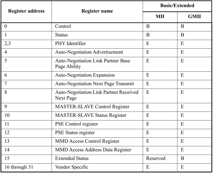
Figure 69.2.1.1 the first 16 registers specified by IEEE
The contents of these 16 registers are also explained in detail in the protocol, which will not be analyzed here. Later, we will take the LAN8720A PHY used by the ALPHA development board as an example to analyze the registers of the PHY chip in detail.
69.2.2 detailed explanation of lan8720a
Although this tutorial explains the PHY LAN8720A, as mentioned earlier, IEEE specifies the functions of the first 16 registers of phy. Therefore, if the board you use uses PHY chips from other manufacturers, you can also see this section.
1. Introduction to LAN8720A
LAN8720A is a low-power 10/100M single Ethernet PHY layer chip, which can be applied to set-top box, network printer, embedded communication equipment, IP phone and other fields. I/O pin voltage complies with IEEE802.3-2005 standard. LAN8720A supports communication with Ethernet MAC layer through RMII interface, built-in 10-BASE-T/100BASE-TX full duplex transmission module, and supports 10Mbps and 100Mbps. LAN8720A can select the best connection mode (speed and duplex mode) with the destination host through self negotiation. HP auto mdix auto flip function is supported, and the connection can be changed to direct connection or cross connection without changing the network cable.
The main features of LAN8720A are as follows:
·High performance 10/100M Ethernet transmission module
·RMII interface is supported to reduce the number of pins
·Full duplex and half duplex modes are supported
·Two status LED outputs
·A 25M crystal oscillator can be used to reduce costs
·Support self negotiation mode
·Support HP auto mdix auto flip function
·Support SMI serial management interface
·Support MAC interface
The functional block diagram of LAN8720A is shown in figure 69.2.2.1.
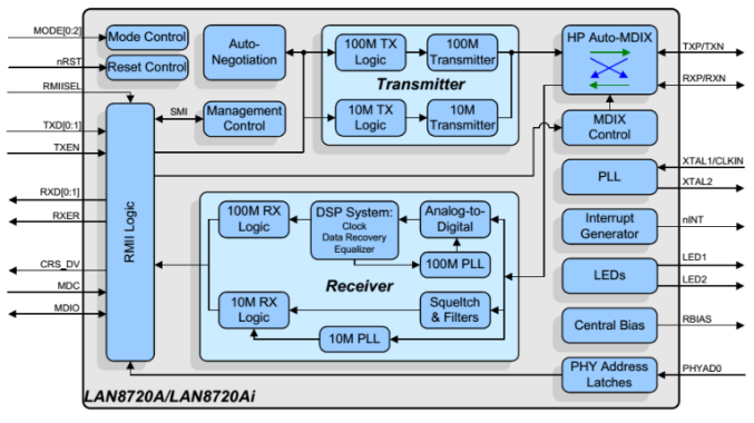
Figure 69.2.2.1 functional block diagram of lan8720a
2. LAN8720A interrupt management
The device management interface of LAN8720A supports the interrupt function of non IEEE 802.3 specification. When an interrupt event occurs and the interrupt bit of the corresponding event is enabled, LAN8720A will generate a low-level effective interrupt signal at Nint (pin 14). The interrupt system of LAN8720A provides two interrupt modes: Main interrupt mode and multiplex interrupt mode. The main interrupt mode is the default interrupt mode. The LAN8720A works in the main interrupt mode after power on or reset. When the ALTINT bit of the mode control / status register (decimal address 17) is 0, the LAN8720A works in the main mode and when the ALTINT bit is 1, it works in the multiplex interrupt mode. Although the ALPHA development board of punctual atom says that the interrupt pin of LAN8720A is connected to I.MX6ULL, it does not use the interrupt function. For the specific usage of interrupt, please refer to pages 29 ~ 30 of LAN8720A data manual.
3. PHY address setting
The MAC layer reads and writes phys through the MDIO/MDC bus. MDIO can control up to 32 PHY chips and operate different phys through different PHY chip addresses. LAN8720A sets its PHY address by setting RXER/PHYAD0 pin, which is 0 by default. Its address setting is shown in table 69.2.2.1.
RXER/PHYAD0 pin status PHY address
Pull up 0X01
Drop down (default) 0X00
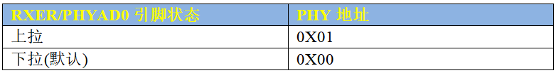
Table 69.2.2.1 LAN8720A address setting
The RXER/PHYAD0 pin on LAN8720A of ENET1 network of punctual atom ALPHA development board is in the default state (there is a 10K pull-down on the schematic diagram, but there is no welding), so the address of LAN8720A on ENET1 is 0. The RXER/PHYAD0 pin of LAN8720A on ENET2 network is connected with a 10K pull-up resistor, so the address of LAN8720A on ENET2 is 1.
4. nINT/REFCLKO configuration
nINTSEL pin (pin 2) is used to set the function of nINT/REFCLKO pin (pin 14). nINTSEL configuration is shown in table 69.2.2.2..
nINTSEL Pin value mode nINT/REFCLKO pin function
nINTSEL= 0 REF_CLK Out mode nINT/REFCLKO as REF_CLK clock source
Nintsel = 1 (default) REF_CLK In mode nINT/REFCLKO as interrupt pin
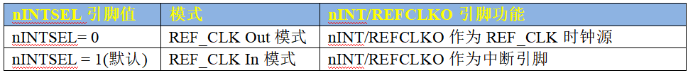
Table 69.2.2.2 nINTSEL configuration
For the two LAN8720A of ALPHA development board of punctual atom, they all work in the default REF_CLK In mode. When LAN8720A works in ref_ In CLK in mode, 50MHz external clock signal shall be connected to XTAL1/CKIN pin (pin 5) of LAN8720, as shown in figure 69.2.2.3:
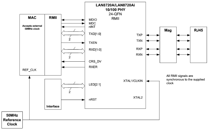
Figure 69.2.2.3 REF_CLK connects external 50MHz clock signal
In order to reduce the cost, the LAN8720A can generate ref from an external 25MHz crystal oscillator_ CLK clock. To use this function, it should work in REF_CLK Out mode. When working in REF_CLO Out mode ref_ The clock source of CLK is shown in figure 69.2.2.4.
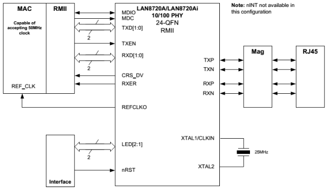
Figure 69.2.2.4 ref_ Ref in CLK out mode_ CLK clock source
As mentioned earlier, the ALPHA development board of punctual atom works in Ref_ In CLK in mode, therefore, an external 50MHz clock signal is required. I.MX6ULL has a dedicated network clock pin. Therefore, the ALPHA development board is through enet1 of I.MX6ULL_ REF_ CLK and ENET2_REF_CLK uses these two network clock pins to provide 50MHz clock for LAN8720A.
5. LAN8720A internal register
The first 16 registers of LAN8720A meet the requirements of IEEE. Here we only introduce several common registers. The first is BCR (basic control rgmaster) register with address 0. The bits of BCR register are shown in table 69.2.2.3.
Bit description type
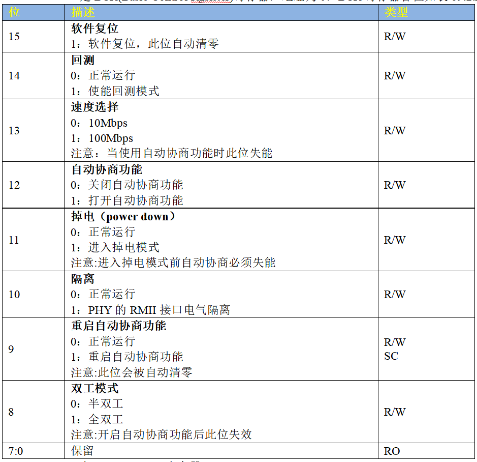
Table 69.2.2.3 BCR register
The key point of configuring the PHY chip is to configure the BCR register. Since LAN8720A is a 10/100M PHY, the 1000M related configuration is not reflected in table 69.2.2.3. However, the configuration related to 10/100M is completely consistent with the provisions of IEEE. You can choose another 10/100M PHY chip for comparison, such as KSZ8081 used by NXP official EVK development board.
Next, take a look at the BSR(Basic Status Register) register. The address is 1. This register is the status register of PHY. The working status of PHY chip can be obtained through this register. The bits of BSR register are shown in table 69.2.2.4:
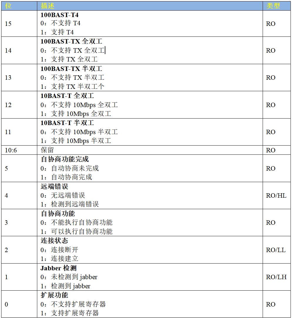
Table 69.2.2.4 BSR registers
As can be seen from table 69.2.2.4, compared with the IEEE standard, the BSR register of LAN8720A is a few bits less. It doesn't matter. No matter what PHY chip, as long as the implemented bits are consistent with the IEEE standard. By reading the value of BSR register, we can get the current connection speed, duplex state and connection state.
Next, take a look at PHY ID register 1 and ID register 2 of LAN8720A. The addresses are 2 and 3, followed by register 2 and register 3. Both registers are ID registers of phy. IEEE specifies that register 2 and register 3 are ID registers of phy, which form a 32-bit unique ID value. IEEE specifies an ID composition method called OUI. Its full name is Organizationally Unique Identifier. OUI has 32 bits in total and is divided into three parts: 22 bit ID+6-bit manufacturer model ID+4-bit manufacturer version ID. the composition is shown in figure 69.2.2.5:
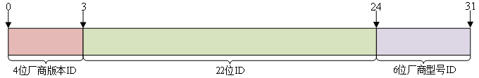
Figure 69.2.2.5 OUI composition
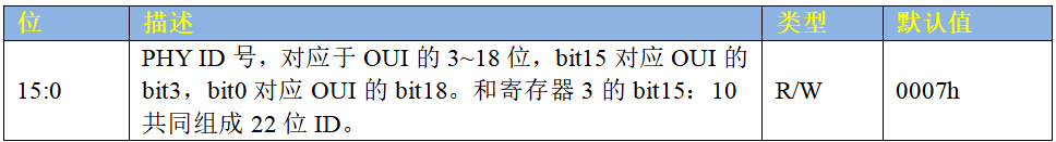
Table 69.2.2.5 PHY ID register 2
ID register 3 is shown in table 69.2.2.6:
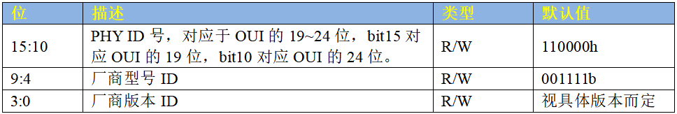
Table 69.2.2.6 PHY ID register 3
Finally, let's take a look at the special control / status register of LAN8720A. The address of this register is 31. The register content is customized by LAN8720A manufacturer. The bits of this register are shown in table 69.2.2.7:
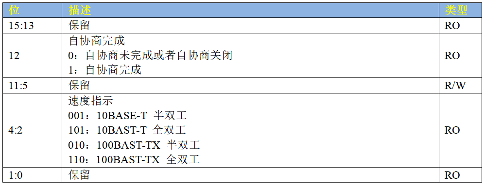
Table 69.2.2.7 LAN8720A special control / status register
In the special control / status register, we are concerned about the three bits bit2~bit4, because the connection status and speed are determined through these three bits. That's all for the PHY of LAN8720A.
69.3 Linux kernel network driver framework
69.3.1 net_device structure
The Linux kernel uses net_ The device structure represents a specific network device, net_device is the soul of the whole network drive. The core of network driver is to initialize net_ Each member variable in the device structure, and then net after initialization_ Device is registered in the Linux kernel. net_ The device structure is defined in include/linux/netdevice.h, net_device is a huge structure with the following contents (with reduction):
Example code 69.3.1.1 net_device structural morphology
1   struct net_device {
2       char            			name[IFNAMSIZ];
3       struct hlist_node   	name_hlist;
4       char            			*ifalias;
5       /*
6        *  I/O specific fields
7        *  FIXME: Merge these and struct ifmap into one
8        */
9       unsigned long    		mem_end;
10      unsigned long    		mem_start;
11      unsigned long     		base_addr;
12      int         			irq;
13
14      atomic_t        		carrier_changes;
15
16      /*
17       *  Some hardware also needs these fields (state,dev_list,
18       *  napi_list,unreg_list,close_list) but they are not
19       *  part of the usual set specified in Space.c.
20       */
21
22      unsigned long       	state;
23
24      struct list_head    	dev_list;
25      struct list_head    	napi_list;
26      struct list_head    	unreg_list;
27      struct list_head    	close_list;
......
60      const struct net_device_ops *netdev_ops;
61      const struct ethtool_ops 	*ethtool_ops;
62  #ifdef CONFIG_NET_SWITCHDEV
63      const struct swdev_ops 		*swdev_ops;
64  #endif
65
66      const struct header_ops 		*header_ops;
67
68      unsigned int        	flags;
......
77      unsigned char       	if_port;
78      unsigned char       	dma;
79
80      unsigned int        	mtu;
81      unsigned short      	type;
82      unsigned short      	hard_header_len;
83
84      unsigned short      	needed_headroom;
85      unsigned short      	needed_tailroom;
86
87      /* Interface address info. */
88      unsigned char       	perm_addr[MAX_ADDR_LEN];
89      unsigned char       	addr_assign_type;
90      unsigned char       	addr_len;
......
130 /*
131  * Cache lines mostly used on receive path (including  eth_type_trans())
132  */
133     unsigned long       	last_rx;
134
135     /* Interface address info used in eth_type_trans() */
136     unsigned char       	*dev_addr;
137
138
139 #ifdef CONFIG_SYSFS
140     struct netdev_rx_queue  *_rx;
141
142     unsigned int        	num_rx_queues;
143     unsigned int        	real_num_rx_queues;
144
145 #endif
......
158 /*
159  * Cache lines mostly used on transmit path
160  */
161     struct netdev_queue 	*_tx 	____cacheline_aligned_in_smp;
162     unsigned int        	num_tx_queues;
163     unsigned int        	real_num_tx_queues;
164     struct Qdisc        	*qdisc;
165     unsigned long       	tx_queue_len;
166     spinlock_t      		tx_global_lock;
167     int         			watchdog_timeo;
......
173     /* These may be needed for future network-power-down code. */
174
175     /*
176      * trans_start here is expensive for high speed devices on SMP,
177      * please use netdev_queue->trans_start instead.
178      */
179     unsigned long       	trans_start;
......
248     struct phy_device 	*phydev;
249     struct lock_class_key *qdisc_tx_busylock;
250 };
Some key member variables are described below:
Line 2: name Is the name of the network device.
Line 9: mem_end Is the end address of shared memory.
Line 10: mem_start Is the starting address of shared memory.
Line 11: base_addr It's a network device I/O Address.
Line 12: irq Is the interrupt number of the network device.
Line 24: dev_list Is the global network device list.
Line 25: napi_list yes napi List entry of network devices.
Line 26: unreg_list Yes, log off(unregister)Network device list entry for.
Line 27: close_list Is the closed network device list entry.
Line 60: netdev_ops It is the operation set function of network devices, including a series of network device operation callback functions, similar to those in character devices file_operations,I'll explain later netdev_ops Structure.
Line 61: ethtool_ops Is a set of related functions of network management tools. User space network management tools will call the related functions in this structure to obtain the network card status or configure the network card.
Line 66: header_ops It is the set of related operation functions of the header, such as creation, parsing, buffering, etc.
Line 68: flags Is the network interface flag. The flag type is defined in include/uapi/linux/if.h In the file, it is an enumeration type with the following contents:
Example code 69.3.1.2 Network flag type
1  enum net_device_flags {
2   	IFF_UP         		= 1<<0,  /* sysfs */
3   	IFF_BROADCAST   	= 1<<1,  /* volatile */
4   	IFF_DEBUG        	= 1<<2,  /* sysfs */
5   	IFF_LOOPBACK     	= 1<<3,  /* volatile */
6   	IFF_POINTOPOINT  	= 1<<4,  /* volatile */
7   	IFF_NOTRAILERS  	= 1<<5,  /* sysfs */
8   	IFF_RUNNING      	= 1<<6,  /* volatile */
9   	IFF_NOARP         	= 1<<7,  /* sysfs */
10  	IFF_PROMISC      	= 1<<8,  /* sysfs */
11  	IFF_ALLMULTI     	= 1<<9,  /* sysfs */
12  	IFF_MASTER       	= 1<<10, /* volatile */
13  	IFF_SLAVE        	= 1<<11, /* volatile */
14  	IFF_MULTICAST    	= 1<<12, /* sysfs */
15  	IFF_PORTSEL      	= 1<<13, /* sysfs */
16  	IFF_AUTOMEDIA    	= 1<<14, /* sysfs */
17  	IFF_DYNAMIC      	= 1<<15, /* sysfs */
18  	IFF_LOWER_UP     	= 1<<16, /* volatile */
19  	IFF_DORMANT      	= 1<<17, /* volatile */
20  	IFF_ECHO          	= 1<<18, /* volatile */
21 };
Continue back to example code 69.3.1.1 Keep looking net_device Structure.
Line 77: if_port Specify the port type of the interface. If the device supports multiple ports, it can pass through if_port To specify the port type used. Optional port types are defined in include/uapi/linux/netdevice.h Is an enumeration type, as shown below:
Example code 69.3.1.3 port type
1  enum {
2  		IF_PORT_UNKNOWN = 0,
3  		IF_PORT_10BASE2,
4 		IF_PORT_10BASET,
5      	IF_PORT_AUI,
6      	IF_PORT_100BASET,
7      	IF_PORT_100BASETX,
8      	IF_PORT_100BASEFX
9  };
Line 78: dma Is used by network devices DMA Channel, not all devices will use it DMA.
Line 80: mtu It is the largest transmission unit in the network, 1500.
Line 81: type Used to specify ARP Type of module, Ethernet ARP Interface is ARPHRD_ETHER,Linux Supported by the kernel ARP Agreement defined in include/uapi/linux/if_arp.h You can check it yourself.
Line 88: perm_addr Is a permanent hardware address. If a network card device has a permanent hardware address, it will be filled in perm_addr.
Line 90: addr_len Is the hardware address length.
Line 133: last_rx Is the timestamp of the last received packet and records jiffies.
Line 136: dev_addr It is also a hardware address, which is currently allocated MAC The address can be modified by software.
Line 140:_rx Is a receive queue.
Line 142: num_rx_queues Is the number of receive queues, which is called register_netdev When registering a network device, a specified number of receive queues will be allocated.
Line 143: real_num_rx_queues Is the number of queues currently active.
Line 161:_tx Is the send queue.
Line 162: num_tx_queues Is the number of send queues, by alloc_netdev_mq Function allocates a specified number of send queues.
Line 163: real_num_tx_queues Is the number of currently valid send queues.
Line 179: trans_start Is the timestamp of the last packet sent, and records jiffies.
Line 248: phydev Is corresponding PHY Equipment.
1,apply net_device
 When writing a network driver, you must first apply net_device,use alloc_netdev Function to apply net_device,This is a macro, which is defined as follows:
Example code 69.3.1.4 alloc_netdev
1 #define alloc_netdev(sizeof_priv, name, name_assign_type, setup) \
2   alloc_netdev_mqs(sizeof_priv, name, name_assign_type, setup, 1, 1)
It can be seen that alloc_netdev The essence of is alloc_netdev_mqs Function. The prototype of this function is as follows
struct net_device * alloc_netdev_mqs ( int sizeof_priv,
const char *name,
void (*setup) (struct net_device *))
unsigned int txqs,
unsigned int rxqs);
Function parameters and return values have the following meanings:
sizeof_priv: private block size.
Name: device name.
setup: callback function, initialize the device's device and call this function.
txqs: number of allocated send queues.
rxqs: number of allocated receive queues.
Return value: if the application is successful, the net to which the application is sent will be returned_ Device pointer, NULL will be returned in case of failure.
In fact, there are many kinds of network devices. Don't think there is only Ethernet. The Linux kernel supports many network interfaces, such as fiber distributed data interface (FDDI), Ethernet device (Ethernet), infrared data interface (InDA), high performance parallel interface (HPPI), CAN network, etc. The kernel is designed for different network devices in alloc_netdev provides a layer of encapsulation on the basis of netdev, such as Ethernet explained in this chapter and net for Ethernet encapsulation_ The device application function is alloc_etherdev and, which is also a macro, are as follows:
Example code 69.3.1.5 alloc_etherdev function
1 #define alloc_etherdev(sizeof_priv) alloc_etherdev_mq(sizeof_priv, 1)
2 #define alloc_etherdev_mq(sizeof_priv, count) alloc_etherdev_mqs(sizeof_priv, count, count)
As you can see, alloc_etherdev Ultimately rely on alloc_etherdev_mqs Function, this function is alloc_netdev_mqs The functions are as follows:
Example code 69.3.1.6 alloc_etherdev_mqs function
1 struct net_device *alloc_etherdev_mqs(int sizeof_priv,
2                                       unsigned int txqs,
3                                  unsigned int rxqs)
4 {
5   return alloc_netdev_mqs(sizeof_priv, "eth%d", NET_NAME_UNKNOWN,
6               ether_setup, txqs, rxqs);
7 }
Line 5 calls alloc_netdev_mqs To apply net_device,Note that the name of the network card set here is“ eth%d",This is the format string. You can enter the development board linux What the system will see later“ eth0","eth1"The name of such network card comes from here. Similarly, Ethernet is set here setup Function is ether_setup,Different network devices setup Different functions, such as CAN Inside the network setup The function is can_setup.
ether_setup The function will be right net_device Perform preliminary initialization. The function contents are as follows:
Example code 69.3.1.7 ether_setup function
1 void ether_setup(struct net_device *dev)
2 {
3 dev->header_ops = ð_header_ops;
4 dev->type = ARPHRD_ETHER;
5 dev->hard_header_len = ETH_HLEN;
6 dev->mtu = ETH_DATA_LEN;
7 dev->addr_len = ETH_ALEN;
8 dev->tx_queue_len = 1000; /* Ethernet wants good queues */
9 dev->flags = IFF_BROADCAST|IFF_MULTICAST;
10 dev->priv_flags |= IFF_TX_SKB_SHARING;
11
12 eth_broadcast_addr(dev->broadcast);
13 }
about net_device That's all for your application. For network devices, use alloc_etherdev or alloc_etherdev_mqs To apply net_device. NXP The official network driver is using alloc_etherdev_mqs To apply net_device.
2,delete net_device
 When we log off the network driver, we need to release the previously applied net_device,The release function is free_netdev,The function prototype is as follows:
void free_netdev(struct net_device *dev)
Function parameters and return values have the following meanings:
dev: the net_device pointer to release.
Return value: none.
3. Register net_device
After the application and initialization of net_device are completed, it is necessary to register net_device with the kernel. The function register_netdev is used. The function prototype is as follows:
int register_netdev(struct net_device *dev)
Function parameters and return values have the following meanings:
dev: the net_device pointer to register.
Return value: 0 registration succeeded, negative value registration failed.
3. Log off net_device
Since there is registration, there must be logoff. To logoff net_device, use the function unregister_netdev. The function prototype is as follows:
void unregister_netdev(struct net_device *dev)
Function parameters and return values have the following meanings:
dev: pointer to the net_device to unregister.
Return value: none.
69.3.2 net_device_ops structure
Net_device has a very important member variable: netdev_ops, which is the pointer type of the structure of net_device_ops, which is the operation set of the network device. The structure of net_device_ops is defined in the include/linux/netdevice.h file. In the structure of net_device_ops, there are some "ndo_" The functions at the beginning need to be implemented by the network driver writers. They do not need to be all implemented, but only some of them can be implemented according to the actual driving situation. The structure content is as follows (the structure is relatively large, and there are reductions here):
Example code 69.3.2.1 net_device_ops structural morphology
1   struct net_device_ops {
2       int         (*ndo_init)(struct net_device *dev);
3       void       	(*ndo_uninit)(struct net_device *dev);
4       int         (*ndo_open)(struct net_device *dev);
5       int         (*ndo_stop)(struct net_device *dev);
6       netdev_tx_t (*ndo_start_xmit) (struct sk_buff *skb,
7                              struct net_device *dev);
8       u16       	(*ndo_select_queue)(struct net_device *dev,
9                               struct sk_buff *skb,
10                              void *accel_priv,
11                              select_queue_fallback_t fallback);
12      void     	(*ndo_change_rx_flags)(struct net_device *dev,
13                                 int flags);
14      void      	(*ndo_set_rx_mode)(struct net_device *dev);
15      int         (*ndo_set_mac_address)(struct net_device *dev,
16                                 void *addr);
17      int         (*ndo_validate_addr)(struct net_device *dev);
18      int         (*ndo_do_ioctl)(struct net_device *dev,
19                              struct ifreq *ifr, int cmd);
20      int         (*ndo_set_config)(struct net_device *dev,
21                                struct ifmap *map);
22      int         (*ndo_change_mtu)(struct net_device *dev,
23                            int new_mtu);
24      int         (*ndo_neigh_setup)(struct net_device *dev,
25                             struct neigh_parms *);
26      void     	(*ndo_tx_timeout) (struct net_device *dev);
......
36  #ifdef CONFIG_NET_POLL_CONTROLLER
37      void     	(*ndo_poll_controller)(struct net_device *dev);
38      int       	(*ndo_netpoll_setup)(struct net_device *dev,
39                               struct netpoll_info *info);
40      void     	(*ndo_netpoll_cleanup)(struct net_device *dev);
41  #endif
......
104     int       	(*ndo_set_features)(struct net_device *dev,
105                             netdev_features_t features);
......
166 };
Line 2: ndo_init Function. This function will be executed when the network device is registered for the first time. The device can do some content that needs to be back initialized in this function. However, this function is not used in general drivers, and virtual network devices may use it.
Line 3: ndo_uninit Function, which will be executed when uninstalling network devices.
Line 4: ndo_open Function. This function will be executed when the network device is opened. The network driver needs to implement this function, which is very important NXP of I.MX series SOC Taking network driver as an example, the following work will be done in this function:
·Enable the network peripheral clock.
·The ring buffer used by the request network.
·Initialize MAC peripherals.
·Bind the PHY corresponding to the interface.
·If NAPI is used, enable the NAPI module through the napi_enable function.
·Open PHY.
·Call netif_tx_start_all_queues to enable the transmission queue, or call the netif_start_queue function.
·......
Line 5: ndo_stop function. This function will be executed when the network device is turned off, and the network driver also needs to implement this function. Take the I.MX series SOC network driver of NXP as an example, the following work will be done in this function:
·Stop PHY.
·Stop NAPI function.
·Stop sending function.
·Turn off MAC.
·Disconnect the PHY.
·Turn off the network clock.
·Free the data buffer.
·......
Line 6: ndo_start_xmit function. This function will be executed when data needs to be sent. One parameter of this function is the sk_buff structure pointer. Sk_buff structure is very important in Linux network driver. Sk_buff saves the data passed from the upper layer to the network driver layer. That is to say, the data to be sent exists in sk_buff. We will talk about sk_buff in detail later If the transmission is successful, this function returns NETDEV_TX_OK. If the transmission fails, it returns NETDEV_TX_BUSY. If the transmission fails, we need to stop the queue.
Line 8: the ndo_select_queue function selects which queue to use when the device supports multiple transmission queues.
Line 14: ndo_set_rx_mode function, which is used to change the address filter list and set the network peripheral register of SOC according to the flags member variable of net_device. For example, flags may be IFF_PROMISC, IFF_ALLMULTI or IFF_MULTICAST, representing hybrid mode, unicast mode or multicast mode respectively.
Line 15: ndo_set_mac_address function. This function is used to modify the MAC address of the network card, set the dev_addr member variable of net_device, and write the MAC address to the hardware register of the network peripheral.
Line 17: ndo_validate_addr function to verify whether the MAC address is legal, that is, to verify whether the MAC address in dev_addr of net_device is legal, directly call is_valid_ether_addr function.
Line 18: ndo_do_ioctl function. This function will be executed when the user program calls IOCTL. For example, phy_mii_ioctl function is usually called directly for the command operation related to PHY chip.
Line 22: ndo_change_mtu function, change the MTU size.
Line 26: the ndo_tx_timeout function will be executed when the transmission timeout occurs. Generally, the transmission timeout is caused by a network problem. Generally, MAC and PHY may be restarted, data transmission may be restarted, etc.
Line 37: the ndo_poll_controller function uses the query method to process the sending and receiving of network card data.
Line 104: ndo_set_features function, modify the features attribute of net_device and set the corresponding hardware attributes.
69.3.3 sk_buff structure
The network is layered. For the application layer, it doesn't matter how the bottom layer works. Just package the data to be sent or received according to the protocol. After packaging, send the data through the dev_queue_xmit function. If you receive the data, use the netif_rx function. Let's take a look at these two functions in turn.
1. dev_queue_xmit function
This function is used to send network data. The function is defined in include/linux/netdevice.h. The function prototype is as follows:
static inline int dev_queue_xmit(struct sk_buff *skb)
Function parameters and return values have the following meanings:
skb: the data to be sent. This is an sk_buff structure pointer, sk_buff is a very important structure in Linux network driver. Network data is based on sk_buff is saved, and each protocol layer is in sk_ Add your own protocol header to the buff, and finally the underlying driver will execute sk_ The data in buff is sent out. The receiving process of network data is just the opposite. The network bottom driver packages the received original data into sk_buff, and then send it to the upper layer protocol. The upper layer will remove the corresponding header, and then send the final data to the user.
Return value: 0 successfully sent, negative value failed to send.
dev_ queue_ The Xmit function is too long. I won't analyze it in detail here, dev_ queue_ The Xmit function ends up with net_ device_ Ndo in OPS operation set_ start_ Xmit function to complete the final sending, ndo_start_xmit is implemented by network driven writers. The whole process is shown in figure 69.3.3.1:
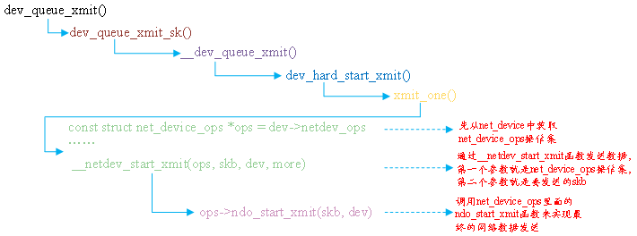
Figure 69.3.3.1 dev_queue_xmit execution process
2,netif_rx function
If the upper layer receives data, use netif_rx function, but the most original network data is generally received through polling, interrupt or NAPI. netif_ The RX function is defined in net/core/dev.c. the function prototype is as follows:
int netif_rx(struct sk_buff *skb)
Function parameters and return values have the following meanings:
skb: save sk of received data_ buff,.
Return value: NET_RX_SUCCESS, NET_RX_DROP packet drop.
Let's focus on sk_buff structure, sk_buff is an important data structure in Linux network, which is used to manage receiving or sending data packets, sk_ The buff structure is defined in include/linux/skbuff.h. The structure contents are as follows (because the structure is relatively large, only some important contents are listed in order to reduce the space):
Example code 69.3.3.1 sk_buff structural morphology
1   struct sk_buff {
2       union {
3           struct {
4               /* These two members must be first. */
5               struct sk_buff      	*next;
6               struct sk_buff      	*prev;
7
8               union {
9                   ktime_t     		tstamp;
10                  struct skb_mstamp skb_mstamp;
11              };
12          };
13          struct rb_node  rbnode; /* used in netem & tcp stack */
14      };
15      struct sock     		*sk;
16      struct net_device   	*dev;
17
18      /*
19       * This is the control buffer. It is free to use for every
20       * layer. Please put your private variables there. If you
21       * want to keep them across layers you have to do a skb_clone()
22       * first. This is owned by whoever has the skb queued ATM.
23       */
24      char            		cb[48] __aligned(8);
25
26      unsigned long       	_skb_refdst;
27      void            		(*destructor)(struct sk_buff *skb);
......
37      unsigned int        	len, data_len;
38      __u16           		mac_len, hdr_len;
......
145     __be16          		protocol;
146     __u16           		transport_header;
147     __u16           		network_header;
148     __u16           		mac_header;
149
150     /* private: */
151     __u32           		headers_end[0];
152     /* public: */
153
154     /* These elements must be at the end, see alloc_skb() for details.  */
155     sk_buff_data_t    	tail;
156     sk_buff_data_t      	end;
157     unsigned char       	*head, *data;
158     unsigned int        	truesize;
159     atomic_t        		users;
160 };
fifth~6 that 's ok: next and prev Point to the next and previous, respectively sk_buff,Form a two-way linked list.
Line 9: tstamp Indicates the timestamp when the packet is received or ready to be sent.
Line 15: sk Represents the current sk_buff Belonging to Socket.
Line 16: dev Represents the current sk_buff Received or sent from which device.
Line 24: cb In order to control the buffer, no matter which layer can freely use this buffer to place private data.
Line 27: destructor Function. When the buffer is released, some actions can be completed in this function.
Line 37: len Is the actual data length, including the data length in the main buffer and the data length in the partition. data_len For data length, only the length of data in the slice is calculated.
Line 38: mac_len Is the head length of the connection layer, i.e MAC The length of the head.
Line 145: protocol agreement.
Line 146: transport_header Is the transport layer header.
Line 147: network_header Network layer header
 Line 148: mac_header Is the link layer header.
Line 155: tail Point to the tail of the actual data.
Line 156: end Points to the end of the buffer.
Line 157: head To the head of the buffer, data Point to the header of the actual data. data and tail Point to the head and tail of the actual data, head and end Points to the head and tail of the buffer. The structure is shown in Figure 69.3.3.2 As shown in:
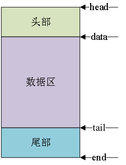
Figure 69.3.3.2 sk_ Structure diagram of buff data area
For SK_ The buff kernel provides a series of operation and management functions. Let's briefly look at some common API functions:
1. Assign sk_buff
To use sk_ Buffs must be allocated first. Let's take a look at alloc first_ SKB is a function defined in include/linux/skbuff.h. The prototype of the function is as follows:
static inline struct sk_buff *alloc_skb(unsigned int size,
gfp_t priority)
Function parameters and return values have the following meanings:
Size: the size to allocate, that is, the size of the skb data segment.
priority: it is a GFP MASK macro, such as GFP_KERNEL,GFP_ATOMIC et al.
Return value: if the allocation is successful, the SK requested will be returned_ The first address of the buff. If it fails, NULL will be returned.
Netdev is often used in network device drivers_ alloc_ SKB to apply for a SKB for receiving for a device_ Buff. This function is also defined in include/linux/skbuff.h. The function prototype is as follows:
static inline struct sk_buff *netdev_alloc_skb(struct net_device *dev,
unsigned int length)
Function parameters and return values have the following meanings:
dev: which device do you want to assign SK to_ buff.
length: the size to allocate.
Return value: if the allocation is successful, the SK requested will be returned_ The first address of the buff. If it fails, NULL will be returned.
2. Release sk_buff
Release SK after use_ Buff, the release function can use kfree_skb. The function is defined in include/linux/skbuff.c. the function prototype is as follows:
void kfree_skb(struct sk_buff *skb)
Function parameters and return values have the following meanings:
skb: SK to release_ buff.
Return value: none.
For network devices, it is best to use the release function as follows:
void dev_kfree_skb (struct sk_buff *skb)
The function only needs one parameter skb, which is the SK to be released_ buff.
3,skb_put,skb_push,sbk_pull and skb_reserve
These four functions are used to change sk_buff, let's take a look at SKB first_ Put function, which is used to extend SKB at the tail_ The data area of buff, that is, skb_buff's tail moves back n bytes, resulting in SKB_ The len of buff is increased by N bytes. The prototype is as follows:
unsigned char *skb_put(struct sk_buff *skb, unsigned int len)
Function parameters and return values have the following meanings:
skb: SK to operate_ buff.
len: how many bytes to add.
Return value: the first address of the extended data area.
skb_ The data area before and after the put operation is shown in figure 69.3.3.3:
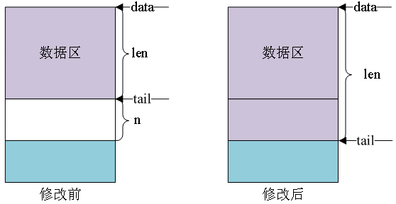
Figure 69.3.3.3 SKB_ Comparison before and after operation of put function
skb_ The push function is used to extend SKB in the header_ In the data area of buff, the function prototype is as follows:
unsigned char *skb_push(struct sk_buff *skb, unsigned int len)
Function parameters and return values have the following meanings:
skb: SK to operate_ buff.
len: how many bytes to add.
Return value: the first address of the new data area after expansion.
skb_ The data area before and after the push operation is shown in figure 69.3.3.4:
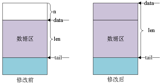
Figure 69.3.3.4 SKB_ Comparison before and after push function operation
sbk_ The pull function is used to pull the data from sk_ Delete data at the starting position of buff's data area. The function prototype is as follows:
unsigned char *skb_pull(struct sk_buff *skb, unsigned int len)
Function parameters and return values have the following meanings:
skb: SK to operate_ buff.
len: number of bytes to delete.
Return value: the first address of the new data area after deletion.
skb_ The data area before and after the pull operation is shown in figure 69.3.3.5:
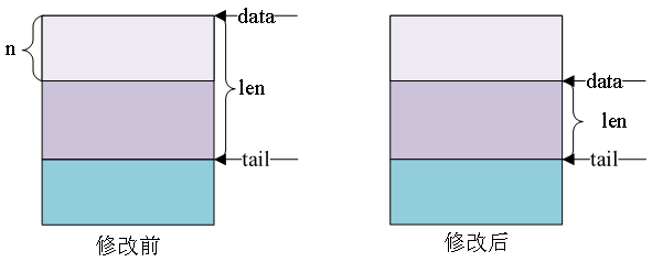
Figure 69.3.3.5 SKB_ Comparison before and after pull function operation
sbk_ The reserve function is used to adjust the header size of the buffer. The method is very simple, say SKB_ The data and tail of buff can be moved back by n bytes at the same time. The function prototype is as follows:
static inline void skb_reserve(struct sk_buff *skb, int len)
Function parameters and return values have the following meanings:
skb: SK to operate_ buff.
len: buffer header size to increase.
Return value: none.
69.3.4 network NAPI processing mechanism
If you have played MCU, you should know that there are two methods to receive data, such as polling or interrupt, such as IIC, SPI, network and other communication interfaces. Network data reception in Linux also includes polling and interrupt. The advantage of interrupt is fast response, timely processing and fast speed when the amount of data is small. However, once the amount of data is large and short frames, it will lead to frequent interrupts and consume a lot of CPU processing time in interrupt processing. Polling is just the opposite. The response is not interrupted in time, but it does not need to consume too much CPU processing time when processing a large amount of data. Based on these two processing methods, Linux proposes another processing method for network data reception: NAPI(New API). NAPI is an efficient network processing technology. The core idea of NAPI is not to use all interrupts to read network data, but to use interrupts to wake up the data receiving service program, and POLL the data in the receiving service program. The advantage of this method is that it can improve the receiving efficiency of short packets and reduce the time of interrupt processing. At present, NAPI has been widely used in Linux network drivers. The network drivers officially written by NXP adopt NAPI mechanism.
The detailed processing process of NAPI is not discussed in this chapter. This chapter briefly explains how to use NAPI in the driver, and the Linux kernel uses the structure napi_struct represents NAPI. You must initialize a NAPI before using napi_struct instance.
1. Initialize NAPI
First, initialize a napi_struct instance, using netif_napi_add function, which is defined in net/core/dev.c. the function prototype is as follows:
void netif_napi_add(struct net_device *dev,
struct napi_struct *napi,
int (*poll)(struct napi_struct *, int),
int weight)
Function parameters and return values have the following meanings:
dev: each NAPI must be associated with a network device. This parameter specifies the network device to be associated with NAPI.
NaPi: NaPi instance to initialize.
poll: the polling function used by NAPI is very important. Generally, this polling function is used to receive network data.
Weight: NAPI default weight, generally NAPI_POLL_WEIGHT.
Return value: none.
2. Delete NAPI
If you want to delete NAPI, use netif_napi_del function is sufficient. The prototype of the function is as follows:
void netif_napi_del(struct napi_struct *napi)
Function parameters and return values have the following meanings:
NaPi: NaPi to delete.
Return value: none.
3. Enable NAPI
After initializing NAPI, it must be enabled to use the function napi_enable, the function prototype is as follows:
inline void napi_enable(struct napi_struct *n)
Function parameters and return values have the following meanings:
n: NAPI to enable.
Return value: none.
4. Close NAPI
Turn off NAPI use NAPI_ The disable function is sufficient. The prototype of the function is as follows:
void napi_disable(struct napi_struct *n)
Function parameters and return values have the following meanings:
n: NAPI to close.
Return value: none.
5. Check whether NAPI can be scheduled
Using NAPI_ schedule_ The prep function checks whether NAPI can be scheduled. The function prototype is as follows:
inline bool napi_schedule_prep(struct napi_struct *n)
Function parameters and return values have the following meanings:
n: NAPI to check.
Return value: returns true if it can be scheduled, and false if it cannot be scheduled.
6. NAPI scheduling
If it can be scheduled, it can be scheduled. Use__ NAPI_ The schedule function completes NAPI scheduling. The prototype of the function is as follows:
void __napi_schedule(struct napi_struct *n)
Function parameters and return values have the following meanings:
n: NAPI to schedule.
Return value: none.
We can also use NaPi_ The schedule function completes NaPi at once_ schedule_ Prep and__ napi_schedule the work of these two functions, NaPi_ The contents of the schedule function are as follows:
Example code 69.3.4.1 napi_schedule function
1 static inline void napi_schedule(struct napi_struct *n)
2 {
3   	if (napi_schedule_prep(n))
4       	__napi_schedule(n);
5 }
From sample code 69.3.4.1 As you can see, napi_schedule The function is right napi_schedule_prep and__napi_schedule Simple packaging, complete judgment and scheduling at one time.
7. NAPI processing completed
After NAPI processing is completed, you need to call napi_complete function to mark the completion of NAPI processing. The function prototype is as follows:
inline void napi_complete(struct napi_struct *n)
Function parameters and return values have the following meanings:
n: Process completed NAPI.
Return value: none.
69.4 introduction to i.mx6ull network driver
69.4.1 I.MX6ULL network peripheral equipment tree
In the last section, we briefly introduced the network driver framework of Linux. In this section, we will briefly analyze the network driver source code of I.MX6ULL. 1. Mx6ull has two 10/100M network MAC peripherals, so I.MX6ULL network driver is mainly the driver of these two network MAC peripherals. The drivers of these two peripherals are the same. Let's analyze one of them. First, it must be the device tree. The I.MX series SOC network binding document of NXP is Documentation/devicetree/bindings/net/fsl-fec.txt. This binding document describes the requirements of I.MX series SOC network device tree nodes.
① . required attributes
Compatible: This is definitely necessary. It is generally "fsl,-fec". For example, the compatible attribute of I.MX6ULL is "FSL, imx6ul FEC" and "FSL, imx6q FEC".
reg: SOC network peripheral register address range.
Interrupts: network interrupts.
PHY mode: PHY interface mode used by the network, MII or RMII.
② . optional attributes
PHY reset gpios: reset pin of phy chip.
PHY reset duration: duration of phy reset pin reset, unit: Ms. This attribute is valid only when the PHY reset gpios attribute is set. If this attribute is not set, the reset duration of the PHY chip reset pin is 1 ms by default, and the value cannot be greater than 1000 ms. if it is greater than 1000 ms, it will be forcibly set to 1 ms.
PHY supply: power regulation of phy chip.
PHY handle: the PHY chip handle connected to this network device.
FSL, Num TX queues: this attribute specifies the number of send queues. If not specified, it defaults to 1.
FSL, Num RX queues: this attribute specifies the number of receive queues. If not specified, it defaults to 2.
FSL, magic packet: this attribute does not need to set a specific value. You can directly write the name of this attribute into the device tree, indicating that hardware magic frame wake-up is supported.
fsl,wakeup_irq: this property sets the wake-up interrupt index.
Stop mode: if this attribute exists, it indicates that the SOC needs to set the GPR bit to request the stop mode.
③ . optional child nodes
MDIO: you can set a child node named "MDIO". This child node is used to specify the MDIO bus used by network peripherals. It is mainly used as a container for PHY nodes, that is, specify PHY related attribute information under the MDIO child node. For specific information, please refer to PHY's binding document Documentation/devicetree/bindings/net/phy.txt.
The related attributes of PHY node are as follows:
interrupts: interrupt attribute, not required.
Interrupt parent: interrupt the controller handle, which is unnecessary.
reg: PHY chip address, required!
Compatible: compatibility list, generally "Ethernet PHY ieee802.3-c22" or "Ethernet PHY ieee802.3-c45", corresponding to 22 clusters and 45 clusters of IEEE802.3 respectively. The default is 22 clusters. It can also be set to other values. If the ID of phy is unknown, the compatible property can be set to "ethernet-phy-idaaa. BBBB". The meanings of AAAA and BBBB are as follows:
AAAA: 16 bit ID register 1 value of PHY, that is, bit3~18, hexadecimal format of OUI.
BBBB: 16 bit ID register 2 value of PHY, that is, bit19~24 of OUI, hexadecimal format.
Max speed: the maximum speed supported by PHY, such as 10, 100, or 1000.
Open imx6ull.dtsi and find the two network peripheral nodes of I.MX6ULL as follows:
Example code 69.4.1.1 Network node information
1  fec1: ethernet@02188000 {
2  		compatible = "fsl,imx6ul-fec", "fsl,imx6q-fec";
3   	reg = <0x02188000 0x4000>;
4   	interrupts = <GIC_SPI 118 IRQ_TYPE_LEVEL_HIGH>,
5            	<GIC_SPI 119 IRQ_TYPE_LEVEL_HIGH>;
6   	clocks = <&clks IMX6UL_CLK_ENET>,
7        		<&clks IMX6UL_CLK_ENET_AHB>,
8        		<&clks IMX6UL_CLK_ENET_PTP>,
9        		<&clks IMX6UL_CLK_ENET_REF>,
10       		<&clks IMX6UL_CLK_ENET_REF>;
11  	clock-names = "ipg", "ahb", "ptp",
12         	"enet_clk_ref", "enet_out";
13  	stop-mode = <&gpr 0x10 3>;
14  	fsl,num-tx-queues=<1>;
15  	fsl,num-rx-queues=<1>;
16  	fsl,magic-packet;
17  	fsl,wakeup_irq = <0>;
18  	status = "disabled";
19 	};
20
21 fec2: ethernet@020b4000 {
22  	compatible = "fsl,imx6ul-fec", "fsl,imx6q-fec";
23  	reg = <0x020b4000 0x4000>;
24  	interrupts = <GIC_SPI 120 IRQ_TYPE_LEVEL_HIGH>,
25           	<GIC_SPI 121 IRQ_TYPE_LEVEL_HIGH>;
26  	clocks = <&clks IMX6UL_CLK_ENET>,
27       	<&clks IMX6UL_CLK_ENET_AHB>,
28       	<&clks IMX6UL_CLK_ENET_PTP>,
29       	<&clks IMX6UL_CLK_ENET2_REF_125M>,
30       	<&clks IMX6UL_CLK_ENET2_REF_125M>;
31  	clock-names = "ipg", "ahb", "ptp",
32            "enet_clk_ref", "enet_out";
33  	stop-mode = <&gpr 0x10 4>;
34  	fsl,num-tx-queues=<1>;
35  	fsl,num-rx-queues=<1>;
36  	fsl,magic-packet;
37  	fsl,wakeup_irq = <0>;
38  	status = "disabled";
39  };
fec1 and fec2 Respectively corresponding I.MX6ULL of ENET1 and ENET2,As for the specific attributes of nodes, I won't analyze them. I've talked about them in detail when explaining the binding document above. Example code 69.4.1.1 yes NXP Officially written, we don't need to modify it, but the sample code is 69.4.1.1 It can't work, and some properties need to be added or modified according to the actual situation. open imx6ull-alientek-emmc.dts,Find the following:
Example code 69.4.1.2 imx6ull-alientek-emmc.dts Network nodes in
1 &fec1 {
2 pinctrl-names = "default";
3 pinctrl-0 = <&pinctrl_enet1
4 &pinctrl_enet1_reset>;
5 phy-mode = "rmii";
6 phy-handle = <ðphy0>;
7 phy-reset-gpios = <&gpio5 7 GPIO_ACTIVE_LOW>;
8 phy-reset-duration = <200>;
9 status = "okay";
10 };
11
12 &fec2 {
13 pinctrl-names = "default";
14 pinctrl-0 = <&pinctrl_enet2
15 &pinctrl_enet2_reset>;
16 phy-mode = "rmii";
17 phy-handle = <ðphy1>;
18 phy-reset-gpios = <&gpio5 8 GPIO_ACTIVE_LOW>;
19 phy-reset-duration = <200>;
20 status = "okay";
21
22 mdio {
23 #address-cells = <1>;
24 #size-cells = <0>;
25
26 ethphy0: ethernet-phy@0 {
27 compatible = "ethernet-phy-ieee802.3-c22";
28 reg = <0>;
29 };
30
31 ethphy1: ethernet-phy@1 {
32 compatible = "ethernet-phy-ieee802.3-c22";
33 reg = <1>;
34 };
35 };
36 };
Example code 69.4.1.2 The author is transplanting Linux The kernel has been based on ALPHA After the development board is modified, it is not NXP The official original node information, so there will be a little difference. It doesn't matter.
Lines 1 ~ 10: node attributes of ENET1 network interface. Lines 3 and 4 set pin pinctrl node information used by ENET1. Line 5 sets the PHY chip interface corresponding to the network as RMII, which should be set according to the actual hardware. In line 6, set the handle of the PHY chip to ethphy0, and the MDIO node will set the PHY information. Other attribute information is easy to understand, which has been basically explained in the binding document above.
Line 1236: the node attributes of the ENET2 network interface are basically the same as those of the ENET1 network interface. The difference is that there are more mdio sub nodes in line 2235. As mentioned earlier in the binding document, the Mido sub node is used to describe the Mido bus, and the PHY node information will be contained in this sub node. There are two PHY sub nodes: ethphy0 and ethphy1, which correspond to the PHY chips of ENET1 and ENET2 respectively. For example, "ethphy0: Ethernet" in line 26- phy@0 ”It is the name of the PHY node of ENET1. The 0 after "@" is the chip address of the PHY chip. The reg attribute also describes the PHY chip address, which is very similar to the IIC device node. There are not many other places. The binding documents have been explained very clearly.
Finally, the description of network related pins in the device tree. Open imx6ull-alientek-emmc.dts and find the following contents:
Example code 69.4.1.2 Network pin pinctrl information
1  pinctrl_enet1: enet1grp {
2   	fsl,pins = <
3       		MX6UL_PAD_ENET1_RX_EN__ENET1_RX_EN  		0x1b0b0
4       		MX6UL_PAD_ENET1_RX_ER__ENET1_RX_ER  		0x1b0b0
5       		MX6UL_PAD_ENET1_RX_DATA0__ENET1_RDATA00 	0x1b0b0
6       		MX6UL_PAD_ENET1_RX_DATA1__ENET1_RDATA01 	0x1b0b0
7       		MX6UL_PAD_ENET1_TX_EN__ENET1_TX_EN  		0x1b0b0
8       		MX6UL_PAD_ENET1_TX_DATA0__ENET1_TDATA00	0x1b0b0
9       		MX6UL_PAD_ENET1_TX_DATA1__ENET1_TDATA01 	0x1b0b0
10      	MX6UL_PAD_ENET1_TX_CLK__ENET1_REF_CLK1  	0x4001b009
11  	>;
12 };
13
14 pinctrl_enet2: enet2grp {
15  	fsl,pins = <
16      	MX6UL_PAD_GPIO1_IO07__ENET2_MDC     		0x1b0b0
17      	MX6UL_PAD_GPIO1_IO06__ENET2_MDIO    		0x1b0b0
18      	MX6UL_PAD_ENET2_RX_EN__ENET2_RX_EN  		0x1b0b0
19      	MX6UL_PAD_ENET2_RX_ER__ENET2_RX_ER  		0x1b0b0
20      	MX6UL_PAD_ENET2_RX_DATA0__ENET2_RDATA00 	0x1b0b0
21      	MX6UL_PAD_ENET2_RX_DATA1__ENET2_RDATA01 	0x1b0b0
22      	MX6UL_PAD_ENET2_TX_EN__ENET2_TX_EN  		0x1b0b0
23      	MX6UL_PAD_ENET2_TX_DATA0__ENET2_TDATA00 	0x1b0b0
24      	MX6UL_PAD_ENET2_TX_DATA1__ENET2_TDATA01 	0x1b0b0
25      	MX6UL_PAD_ENET2_TX_CLK__ENET2_REF_CLK2  	0x4001b009
26  	>;
27 };
28
29  /*enet1 reset zuozhongkai*/
30 pinctrl_enet1_reset: enet1resetgrp {
31     	fsl,pins = <
32      	/* used for enet1  reset */
33      	MX6ULL_PAD_SNVS_TAMPER7__GPIO5_IO07      	0x10B0
34        	>;
35 };
36
37 /*enet2 reset zuozhongkai*/
38 pinctrl_enet2_reset: enet2resetgrp {
39    	fsl,pins = <
40      	/* used for enet2  reset */
41        	MX6ULL_PAD_SNVS_TAMPER8__GPIO5_IO08      	0x10B0
42    	>;
43  };
pinctrl_enet1 and pinctrl_enet1_reset ask ENET1 be-all IO Pin pinctrl Information is divided into two parts mainly because ENET1 The reset pin is GPIO5_IO07,and GPIO5_IO07 The corresponding pin is SNVS_TAMPER7,To put iomuxc_snvs Node, so it is divided into two parts.
Note lines 16 and 17, which are set GPIO1_IO07 and GPIO1_IO06 by ENET2 of MDC and MDIO,You may wonder, why not set it to ENET1 of MDC and MDIO And? According to the author's actual measurement, when two network ports are opened, the GPIO1_IO07 and GPIO1_IO06 Set to ENET1 of MDC and MDIO It will cause the network to work abnormally. As I said earlier, one MDIO The interface can manage 32 PHY,So set ENET2 of MDC and MDIO It can also be managed in the future ENET1 Upper PHY Chip.
69.4.2 brief analysis of i.mx6ull network driver source code
1,fec_ Analysis of probe function
For I.MX6ULL, the network driver is mainly divided into two parts: I.MX6ULL network peripheral driver and PHY chip driver. The network peripheral driver is written by NXP. PHY chip has a general driver file. Some PHY chip manufacturers will also write corresponding PHY drivers for their own chips. Generally speaking, we don't need to write any driver for SOC with built-in network MAC + external PHY chip, which can be used directly. However, in order to learn, we still need to briefly analyze the specific network driven writing process.
First, let's take a look at the network controller driver of I.MX6ULL. From the example code 69.4.1.1, we can see that the compatible attribute has two values "FSL, imx6ul FEC" and "FSL, imx6q FEC". You can find the corresponding drive file by searching the two strings in the linux kernel source code. The drive file is drivers/net/ethernet/freescale/fec_main.c, open fec_main.c, find the following:
Example code 69.4.2.1 I.MX series SOC Network platform driver matching table
1  static const struct of_device_id fec_dt_ids[] = {
2   	{ .compatible = "fsl,imx25-fec", .data =
				&fec_devtype[IMX25_FEC], },
3   	{ .compatible = "fsl,imx27-fec", .data =
			&fec_devtype[IMX27_FEC], },
4   	{ .compatible = "fsl,imx28-fec", .data =
		&fec_devtype[IMX28_FEC], },
5   	{ .compatible = "fsl,imx6q-fec", .data =
			&fec_devtype[IMX6Q_FEC], },
6   	{ .compatible = "fsl,mvf600-fec", .data =
			&fec_devtype[MVF600_FEC], },
7   	{ .compatible = "fsl,imx6sx-fec", .data =
			&fec_devtype[IMX6SX_FEC], },
8   	{ .compatible = "fsl,imx6ul-fec", .data =
			&fec_devtype[IMX6UL_FEC], },
9   	 { /* sentinel */ }
10 };
11
12 static struct platform_driver fec_driver = {
13  	.driver = {
14      	.name   = DRIVER_NAME,
15      	.pm = &fec_pm_ops,
16      	.of_match_table = fec_dt_ids,
17  },
18  	.id_table = fec_devtype,
19  	.probe  = fec_probe,
20  	.remove = fec_drv_remove,
21 };
Line 8, the matching table contains“ fsl,imx6ul-fec",Therefore, in the device tree and driver matching, when the matching is successful, the value in line 19 fec_probe The function will execute. Let's analyze it briefly fec_probe Function. The function contents are as follows:
Example code 69.4.2.1 fec_probe function
1   static int fec_probe(struct platform_device *pdev)
2   {
3       struct fec_enet_private *fep;
4       struct fec_platform_data *pdata;
5       struct net_device *ndev;
6       int i, irq, ret = 0;
7       struct resource *r;
8       const struct of_device_id *of_id;
9       static int dev_id;
10      struct device_node *np = pdev->dev.of_node, *phy_node;
11      int num_tx_qs;
12      int num_rx_qs;
13
14      fec_enet_get_queue_num(pdev, &num_tx_qs, &num_rx_qs);
15
16      /* Init network device */
17      ndev = alloc_etherdev_mqs(sizeof(struct fec_enet_private),
18                    num_tx_qs, num_rx_qs);
19      if (!ndev)
20          return -ENOMEM;
21
22      SET_NETDEV_DEV(ndev, &pdev->dev);
23
24      /* setup board info structure */
25      fep = netdev_priv(ndev);
26
27      of_id = of_match_device(fec_dt_ids, &pdev->dev);
28      if (of_id)
29          pdev->id_entry = of_id->data;
30      fep->quirks = pdev->id_entry->driver_data;
31
32      fep->netdev = ndev;
33      fep->num_rx_queues = num_rx_qs;
34      fep->num_tx_queues = num_tx_qs;
35
36  #if !defined(CONFIG_M5272)
37      /* default enable pause frame auto negotiation */
38      if (fep->quirks & FEC_QUIRK_HAS_GBIT)
39          fep->pause_flag |= FEC_PAUSE_FLAG_AUTONEG;
40  #endif
41
42      /* Select default pin state */
43      pinctrl_pm_select_default_state(&pdev->dev);
44
45      r = platform_get_resource(pdev, IORESOURCE_MEM, 0);
46      fep->hwp = devm_ioremap_resource(&pdev->dev, r);
47      if (IS_ERR(fep->hwp)) {
48          ret = PTR_ERR(fep->hwp);
49          goto failed_ioremap;
50      }
51
52      fep->pdev = pdev;
53      fep->dev_id = dev_id++;
54
55      platform_set_drvdata(pdev, ndev);
56
57      fec_enet_of_parse_stop_mode(pdev);
58
59      if (of_get_property(np, "fsl,magic-packet", NULL))
60          fep->wol_flag |= FEC_WOL_HAS_MAGIC_PACKET;
61
62      phy_node = of_parse_phandle(np, "phy-handle", 0);
63      if (!phy_node && of_phy_is_fixed_link(np)) {
64          ret = of_phy_register_fixed_link(np);
65          if (ret < 0) {
66              dev_err(&pdev->dev,
67                  "broken fixed-link specification\n");
68              goto failed_phy;
69          }
70          phy_node = of_node_get(np);
71      }
72      fep->phy_node = phy_node;
73
74      ret = of_get_phy_mode(pdev->dev.of_node);
75      if (ret < 0) {
76          pdata = dev_get_platdata(&pdev->dev);
77          if (pdata)
78              fep->phy_interface = pdata->phy;
79          else
80              fep->phy_interface = PHY_INTERFACE_MODE_MII;
81      } else {
82          fep->phy_interface = ret;
83      }
84
85      fep->clk_ipg = devm_clk_get(&pdev->dev, "ipg");
86      if (IS_ERR(fep->clk_ipg)) {
87          ret = PTR_ERR(fep->clk_ipg);
88          goto failed_clk;
89      }
90
91      fep->clk_ahb = devm_clk_get(&pdev->dev, "ahb");
92      if (IS_ERR(fep->clk_ahb)) {
93          ret = PTR_ERR(fep->clk_ahb);
94          goto failed_clk;
95      }
96
97      fep->itr_clk_rate = clk_get_rate(fep->clk_ahb);
98
99      /* enet_out is optional, depends on board */
100     fep->clk_enet_out = devm_clk_get(&pdev->dev, "enet_out");
101     if (IS_ERR(fep->clk_enet_out))
102         fep->clk_enet_out = NULL;
103
104     fep->ptp_clk_on = false;
105     mutex_init(&fep->ptp_clk_mutex);
106
107     /* clk_ref is optional, depends on board */
108     fep->clk_ref = devm_clk_get(&pdev->dev, "enet_clk_ref");
109     if (IS_ERR(fep->clk_ref))
110         fep->clk_ref = NULL;
111
112     fep->bufdesc_ex = fep->quirks & FEC_QUIRK_HAS_BUFDESC_EX;
113     fep->clk_ptp = devm_clk_get(&pdev->dev, "ptp");
114     if (IS_ERR(fep->clk_ptp)) {
115         fep->clk_ptp = NULL;
116         fep->bufdesc_ex = false;
117     }
118
119     pm_runtime_enable(&pdev->dev);
120     ret = fec_enet_clk_enable(ndev, true);
121     if (ret)
122         goto failed_clk;
123
124     fep->reg_phy = devm_regulator_get(&pdev->dev, "phy");
125     if (!IS_ERR(fep->reg_phy)) {
126         ret = regulator_enable(fep->reg_phy);
127         if (ret) {
128             dev_err(&pdev->dev,
129                 "Failed to enable phy regulator: %d\n", ret);
130             goto failed_regulator;
131         }
132     } else {
133         fep->reg_phy = NULL;
134     }
135
136     fec_reset_phy(pdev);
137
138     if (fep->bufdesc_ex)
139         fec_ptp_init(pdev);
140
141     ret = fec_enet_init(ndev);
142     if (ret)
143         goto failed_init;
144
145     for (i = 0; i < FEC_IRQ_NUM; i++) {
146         irq = platform_get_irq(pdev, i);
147         if (irq < 0) {
148             if (i)
149                 break;
150             ret = irq;
151             goto failed_irq;
152         }
153         ret = devm_request_irq(&pdev->dev, irq, fec_enet_interrupt,
154                        0, pdev->name, ndev);
155         if (ret)
156             goto failed_irq;
157
158         fep->irq[i] = irq;
159     }
160
161     ret = of_property_read_u32(np, "fsl,wakeup_irq", &irq);
162     if (!ret && irq < FEC_IRQ_NUM)
163         fep->wake_irq = fep->irq[irq];
164     else
165         fep->wake_irq = fep->irq[0];
166
167     init_completion(&fep->mdio_done);
168     ret = fec_enet_mii_init(pdev);
169     if (ret)
170         goto failed_mii_init;
171
172     /* Carrier starts down, phylib will bring it up */
173     netif_carrier_off(ndev);
174     fec_enet_clk_enable(ndev, false);
175     pinctrl_pm_select_sleep_state(&pdev->dev);
176
177     ret = register_netdev(ndev);
178     if (ret)
179         goto failed_register;
180
181     device_init_wakeup(&ndev->dev, fep->wol_flag &
182                FEC_WOL_HAS_MAGIC_PACKET);
183
184     if (fep->bufdesc_ex && fep->ptp_clock)
185         netdev_info(ndev, "registered PHC device %d\n", fep->dev_id);
186
187     fep->rx_copybreak = COPYBREAK_DEFAULT;
188     INIT_WORK(&fep->tx_timeout_work, fec_enet_timeout_work);
189     return 0;
......
206     return ret;
207 }
Line 14, use fec_enet_get_queue_num Function to get the data in the device tree“ fsl,num-tx-queues"And“ fsl,num-rx-queues"These two attribute values, that is, the size of the send queue and the receive queue, are set to 1 in the device tree.
Line 17, use alloc_etherdev_mqs Function application net_device.
Line 25, get net_device First address of private data memory in, net_device Private data in is used to store I.MX6ULL Network device structure, which is fec_enet_private.
Line 30, then all“ fep->"The first line of code is to initialize each member variable of the network device structure. The structure type is fec_enet_privatede,This structure is NXP Self defined.
In line 45, obtain the starting address of relevant registers of I.MX6ULL network peripheral (ENET) in the device tree, the starting address of register 0X02188000 of ENET1 and the starting address of register 0X20B4000 of ENET2.
In line 46, perform virtual address conversion for the address obtained in line 45, and the starting address of the converted ENET virtual register is saved in the hwp member of fep.
In line 57, use the fec_enet_of_parse_stop_mode function to parse the stop mode attribute value of ENET in the device tree. The attribute name is "stop mode", which we do not use.
In line 59, find out whether the "FSL, magic packet" attribute exists from the device tree. If it exists, it indicates that there is a magic packet. If there is a magic packet, or calculate the wol_flag member of fep with FEC_WOL_HAS_MAGIC_PACKET, that is, register in wol_flag to support magic packets.
In line 62, get the value of the "PHY handle" attribute. The PHY handle attribute specifies the device node corresponding to the I.MX6ULL network peripheral to get PHY. In the fec1 and fec2 nodes of the device tree, the values of the PHY handle attribute are:
phy-handle = <ðphy0>;
phy-handle = <ðphy1>;
Both ethphy0 and ethphy1 are defined under the mdio child node, as follows:
mdio {
#address-cells = <1>;
#size-cells = <0>;
ethphy0: ethernet-phy@0 {
	compatible = "ethernet-phy-ieee802.3-c22";
	reg = <0>;
};
ethphy1: ethernet-phy@1 {
	compatible = "ethernet-phy-ieee802.3-c22";
	reg = <1>;
};
};
It can be seen that both ethphy0 and ethphy1 are related to MDIO, and the MDIO interface is configured with PHY chips. Multiple PHY chips can be configured through one MDIO interface, and different PHY chips can be distinguished through different addresses. The PHY address of ENET in the punctual atom ALPHA development board is 0X00, and the PHY address of ENET2 is 0X01. These two PHY addresses should be told to the Linux system through the device tree, as shown in the following two lines The value after the code @ is the PHY address:
ethphy0: ethernet-phy@2
ethphy1: ethernet-phy@1
Moreover, the reg attribute in the ethphy0 and ethphy1 nodes is also the PHY address. If we want to replace other network PHY chips, the first step is to modify the PHY address in the device tree.
Line 74, get PHY working mode, function of_get_phy_mode will read the value of the attribute PHY mode. "PHY mode" saves the working mode of phy, that is, whether PHY is RMII or MII. Phy in IMX6ULL works in RMII mode. The device tree is described as follows:
Lines 85, 91, 100, 108 and 113 obtain clocks ipg, ahb and eNet respectively_ out,enet_clk_ref and ptp, corresponding to structure fec_enet_private has the following member functions
struct clk *clk_ipg;
struct clk *clk_ahb;
struct clk *clk_ref;
struct clk *clk_enet_out;
struct clk *clk_ptp;
Line 120, enable the clock.
Line 136, call the function fec_reset_phy reset PHY.
Line 141, call the function fec_enet_init() initializes eNet. This function allocates queues, applies for dma, sets MAC addresses, and initializes net_ Netdev of device_ Ops and ethtool_ops members, as shown in figure 69.4.2.1:

Figure 69.4.2.1 setting netdev_ops and ethtool_ops
As can be seen from figure 69.4.2.1, net_ Netdev of device_ Ops and ethtool_ The OPS variables are initialized to FEC respectively_ netdev_ops and fec_enet_ethtool_ops. fec_ enet_ The init function also calls netif_napi_add to set the poll function, indicating that the network driver officially written by NXP is a NAPI compatible driver, as shown in figure 69.4.2.2:

Figure 69.4.2.2 netif_napi_add function
As can be seen from figure 69.4.2.2, through netif_ napi_ The add function adds a NaPi example to the network card. The NaPi driver is used to provide a poll function to poll and process the received data. The poll function here is fec_enet_rx_napi, this function will be explained in detail later when analyzing the network data receiving and processing process.
Finally, FEC_ enet_ The init function sets the hardware registers related to the IMX6ULL network peripherals.
Line 146, get the interrupt number from the device tree.
Line 153, apply for an interrupt, and the interrupt processing function is fec_enet_interrupt, focus! This function will be analyzed later.
In line 161, get the value of the attribute "fsl,wakeup_irq" from the device tree, that is, wake-up interrupt,
In line 167, the initialization completion amount is used for one execution unit to wait for another execution unit to complete something.
Line 168, function fec_enet_mii_init completes the initialization of MII/RMII interface. This function focuses on the two lines of code in figure 69.4.2.3:

Figure 69.4.2.3 mdio read / write function
mii_ The read and write member variables under bus are the operation functions of reading / writing PHY register respectively, which are set as FEC here_ enet_ mdio_ Read and fec_enet_mdio_write, these two functions are the functions of I.MX series SOC to read and write PHY internal registers. Reading or configuring PHY registers will be completed through these two MDIO bus functions. fec_ enet_ mii_ The init function will eventually register the MIDO bus with the Linux kernel. The relevant code is as follows:
Example code 69.4.2.2 fec_enet_mii_init Function registration mdio Bus
1 node = of_get_child_by_name(pdev->dev.of_node, "mdio");
2 	if (node) {
3   	err = of_mdiobus_register(fep->mii_bus, node);
4   	of_node_put(node);
5 	} else {
6   	err = mdiobus_register(fep->mii_bus);
7 }
Example code 69.4.2.2 The first line in is obtained from the device tree mdio Node. If the node exists, it will pass of_mdiobus_register perhaps mdiobus_register To register with the kernel MDIO Bus, if the device tree is used of_mdiobus_register To register MDIO Bus, otherwise use mdiobus_register Function.
Continue back to example code 69.4.2.1, and then analyze the fec_probe function.
Line 173, call the function netif first_ carrier_ Off informs the kernel to close the link first and phylib will open.
Line 174, call the function fec_enet_clk_enable enables the network related clock.
Line 177, call the function register_netdev register net_device!
2. MDIO bus registration
We have talked about MDIO many times. It is used to manage PHY chips. It is divided into MDIO and MDC lines. The Linux kernel specially prepares a bus for MDIO, called MDIO bus, which adopts mii_bus structure, defined in include/linux/phy.h file, MII_ The bus structure is as follows:
Example code 69.4.2.3 mii_bus structural morphology
1  struct mii_bus {
2   	const char *name;
3   	char id[MII_BUS_ID_SIZE];
4   	void *priv;
5   	int (*read)(struct mii_bus *bus, int phy_id, int regnum);
6   	int (*write)(struct mii_bus *bus, int phy_id, int regnum,
u16 val);
7   	int (*reset)(struct mii_bus *bus);
8
9   	/*
10   	 * A lock to ensure that only one thing can read/write
11   	 * the MDIO bus at a time
12   	 */
13  	struct mutex mdio_lock;
14
15  	struct device *parent;
16  	enum {
17      	MDIOBUS_ALLOCATED = 1,
18      	MDIOBUS_REGISTERED,
19      	MDIOBUS_UNREGISTERED,
20      	MDIOBUS_RELEASED,
21  	} state;
22  	struct device dev;
23
24  	/* list of all PHYs on bus */
25  	struct phy_device *phy_map[PHY_MAX_ADDR];
26
27  	/* PHY addresses to be ignored when probing */
28  	u32 phy_mask;
29
30  	/*
31   	 * Pointer to an array of interrupts, each PHY's
32   	 * interrupt at the index matching its address
33   	 */
34  	int *irq;
35 };
The focus is on lines 5 and 6 read and write Function, these two functions are read/some PHY Chip operation function, different SOC his MDIO The main control part is different, so it needs to drive the writer to write it. We were analyzing earlier fec_probe I already talked about the function, fec_probe The function will call fec_enet_mii_init Function complete MII Interface initialization, including initialization mii_bus Lower read and write These two functions. Finally passed of_mdiobus_register perhaps mdiobus_register The function initializes the following mii_bus Register to Linux Kernel, of_mdiobus_register Functions are actually called in the end mdiobus_register Function to complete mii_bus Registered. of_mdiobus_register The function is as follows(Limited to space, there are omissions):
Example code 69.4.2.4 of_mdiobus_register function
1  int of_mdiobus_register(struct mii_bus *mdio, struct device_node *np)
2  {
3   	struct device_node *child;
4   	const __be32 *paddr;
5   	bool scanphys = false;
6   	int addr, rc, i;
7
8   	/* Mask out all PHYs from auto probing.  Instead the PHYs listed
9    	 * in the device tree are populated after the bus has been
	 *registered */
10  	mdio->phy_mask = ~0;
11
12  	/* Clear all the IRQ properties */
13  	if (mdio->irq)
14      	for (i=0; i<PHY_MAX_ADDR; i++)
15          		mdio->irq[i] = PHY_POLL;
16
17  	mdio->dev.of_node = np;
18
19  	/* Register the MDIO bus */
20  	rc = mdiobus_register(mdio);
21  	if (rc)
22      	return rc;
23
24  	/* Loop over the child nodes and register a phy_device for each
one */
25  	for_each_available_child_of_node(np, child) {
26      	addr = of_mdio_parse_addr(&mdio->dev, child);
27      	if (addr < 0) {
28          		scanphys = true;
29          		continue;
30      	}
31
32      	rc = of_mdiobus_register_phy(mdio, child, addr);
33      	if (rc)
34          	continue;
35  	}
36
37  	if (!scanphys)
38      	return 0;
39
......
62  	return 0;
63 }
Line 20, call mdiobus_register Function to Linux Kernel registration mdio Bus!
Line 25, polling mdio All child nodes under node, such as example code 69.4.1.2 Medium“ ethphy0: ethernet-phy@0"And“ ethphy1: ethernet-phy@1"These two child nodes describe PHY Chip information.
Line 26, extract from the child node of the device tree PHY Address, that is ethphy0: ethernet-phy@0"And“ ethphy1: ethernet-phy@1"The two child nodes correspond to PHY Chip address, 0 and 1 respectively.
Line 32, call of_mdiobus_register_phy Function direction Linux Kernel registration phy.
To sum up, of_mdiobus_register Function has two main functions. One is through mdiobus_register Function direction Linux Kernel, the other is through of_mdiobus_register_phy Function registers with the kernel PHY.
Next, let's make a simple analysis of_mdiobus_register_phy Function to see how to Linux Kernel registration PHY Of the equipment, of_mdiobus_register_phy The function contents are as follows:
Example code 69.4.2.5 of_mdiobus_register_phy function
1  static int of_mdiobus_register_phy(struct mii_bus *mdio,
struct device_node *child,
2                    u32 addr)
3  {
4   	struct phy_device *phy;
5   	bool is_c45;
6   	int rc;
7   	u32 phy_id;
8
9   	is_c45 = of_device_is_compatible(child,
10                   "ethernet-phy-ieee802.3-c45");
11
12  	if (!is_c45 && !of_get_phy_id(child, &phy_id))
13      	phy = phy_device_create(mdio, addr, phy_id, 0, NULL);
14  	else
15      	phy = get_phy_device(mdio, addr, is_c45);
16  	if (!phy || IS_ERR(phy))
17      	return 1;
18
19  	rc = irq_of_parse_and_map(child, 0);
20  	if (rc > 0) {
21      	phy->irq = rc;
22      	if (mdio->irq)
23          		mdio->irq[addr] = rc;
24 		} else {
25      	if (mdio->irq)
26          		phy->irq = mdio->irq[addr];
27  	}
28
29  	/* Associate the OF node with the device structure so it
30   	* can be looked up later */
31  	of_node_get(child);
32  	phy->dev.of_node = child;
33
34  	/* All data is now stored in the phy struct;
35   	* register it */
36  	rc = phy_device_register(phy);
37  	if (rc) {
38      	phy_device_free(phy);
39      	of_node_put(child);
40      	return 1;
41  	}
42
43  	dev_dbg(&mdio->dev, "registered phy %s at address %i\n",
44      	child->name, addr);
45
46 		return 0;
47 }
Line 9, use the function of_device_is_compatible inspect PHY Nodal compatible Property is“ ethernet-phy-ieee802.3-c45",If yes, we need to do other processing, which we set in this chapter compatible Attribute is“ ethernet-phy-ieee802.3-c22".
In line 15, call the get_phy_device function to get the PHY device. In this function, call phy_device_create to create a phy_device and return.
Line 19, obtain the interrupt information of PHY chip, which is not used in this chapter.
Line 36, call the phy_device_register function to register the PHY device with the Linux kernel.
It can be seen from the above analysis that when registering the MDIO bus with the Linux kernel, the PHY device will also be registered with the Linux kernel. The process is shown in figure 69.4.2.3:
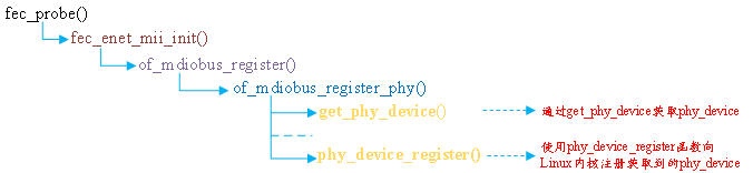
Figure 69.4.2.3 MDIO bus registration process
When registering the MIDO bus, you will find the PHY device from the device tree, and then register the PHY device with the kernel through the phy_device_register function. Next, let's learn about the PHY subsystem.
3. Brief analysis of fec_drv_remove function
When I.MX6ULL network driver is unloaded, fec_drv_remove function will be executed. The content of the function is as follows:
Example code 69.4.2.6 fec_drv_remove function
1  static int fec_drv_remove(struct platform_device *pdev)
2  {
3   	struct net_device *ndev = platform_get_drvdata(pdev);
4   	struct fec_enet_private *fep = netdev_priv(ndev);
5
6   	cancel_delayed_work_sync(&fep->time_keep);
7   	cancel_work_sync(&fep->tx_timeout_work);
8   	unregister_netdev(ndev);
9   	fec_enet_mii_remove(fep);
10  	if (fep->reg_phy)
11      	regulator_disable(fep->reg_phy);
12  	if (fep->ptp_clock)
13      	ptp_clock_unregister(fep->ptp_clock);
14  	of_node_put(fep->phy_node);
15  	free_netdev(ndev);
16
17  	return 0;
18 }
Line 8, call unregister_netdev Function to unregister a previously registered net_device.
Line 9, call fec_enet_mii_remove Function to remove MDIO Bus related content, this function will call mdiobus_unregister To sign out mii_bus,And through the function mdiobus_free Release mii_bus
 Line 15, call free_netdev Function to release the previously applied net_device.
69.4.3 fec_netdev_ops operation set
The fec_probe function sets the net_dev_ops operation set of the network card driver to fec_netdev_ops. The contents of fec_netdev_ops are as follows:
Example code 69.4.3.1 fec_netdev_ops Operation set
1  static const struct net_device_ops fec_netdev_ops = {
2   	.ndo_open       		= fec_enet_open,
3   	.ndo_stop       		= fec_enet_close,
4   	.ndo_start_xmit     	= fec_enet_start_xmit,
5   	.ndo_select_queue   	= fec_enet_select_queue,
6   	.ndo_set_rx_mode    	= set_multicast_list,
7   	.ndo_change_mtu     	= eth_change_mtu,
8   	.ndo_validate_addr  	= eth_validate_addr,
9   	.ndo_tx_timeout     	= fec_timeout,
10  	.ndo_set_mac_address	= fec_set_mac_address,
11  	.ndo_do_ioctl       	= fec_enet_ioctl,
12 #ifdef CONFIG_NET_POLL_CONTROLLER
13  	.ndo_poll_controller	= fec_poll_controller,
14 #endif
15  	.ndo_set_features   	= fec_set_features,
16 };
1,fec_enet_open Function analysis
 When opening a network card fec_enet_open The function will execute. The function source code is as follows(Due to space limitation, some are omitted):
Example code 69.4.3.2 fec_enet_open function
1  static int fec_enet_open(struct net_device *ndev)
2  {
3   	struct fec_enet_private *fep = netdev_priv(ndev);
4   	const struct platform_device_id *id_entry =
5               platform_get_device_id(fep->pdev);
6   	int ret;
7
8   	pinctrl_pm_select_default_state(&fep->pdev->dev);
9   	ret = fec_enet_clk_enable(ndev, true);
10  	if (ret)
11      	return ret;
12
13  	/* I should reset the ring buffers here, but I don't yet know
14   	 * a simple way to do that.
15   	 */
16
17  	ret = fec_enet_alloc_buffers(ndev);
18  	if (ret)
19      	goto err_enet_alloc;
20
21  	/* Init MAC prior to mii bus probe */
22  	fec_restart(ndev);
23
24  	/* Probe and connect to PHY when open the interface */
25  	ret = fec_enet_mii_probe(ndev);
26  	if (ret)
27      	goto err_enet_mii_probe;
28
29  	napi_enable(&fep->napi);
30  	phy_start(fep->phy_dev);
31  	netif_tx_start_all_queues(ndev);
32
......
47
48  	return 0;
49
50 err_enet_mii_probe:
51  	fec_enet_free_buffers(ndev);
52 err_enet_alloc:
53  	fep->miibus_up_failed = true;
54  	if (!fep->mii_bus_share)
55      	pinctrl_pm_select_sleep_state(&fep->pdev->dev);
56  	return ret;
57 }
Line 9, call the fec_enet_clk_enable function to enable the eNet clock.
Line 17, call FEC_ enet_ alloc_ The buffers function applies for ring buffer. FEC will be called in this function_ enet_ alloc_ rxq_ Buffers and fec_enet_alloc_txq_buffers these two functions implement the application of the send queue and the receive queue buffer respectively.
Line 22, restart the network. Generally, FEC will be called when the connection state changes, the transmission times out, or the network is configured_ Restart function.
Line 25, call FEC when the network card is opened_ enet_ mii_ Probe function to detect and connect the corresponding PHY device.
Line 29, call NAPI_ The enable function enables NAPI scheduling.
Line 30, call PHY_ The start function starts the PHY device.
Line 31, call netif_ tx_ start_ all_ The queues function to activate the send queue.
2,fec_ enet_ Analysis of close function
FEC when the network card is turned off_ enet_ The close function will be executed. The function contents are as follows:
Example code 69.4.3.3 fec_enet_close function
1  static int fec_enet_close(struct net_device *ndev)
2  {
3   	struct fec_enet_private *fep = netdev_priv(ndev);
4
5   	phy_stop(fep->phy_dev);
6
7   	if (netif_device_present(ndev)) {
8       		napi_disable(&fep->napi);
9       		netif_tx_disable(ndev);
10      	fec_stop(ndev);
11 	 	}
12
13  	phy_disconnect(fep->phy_dev);
14  	fep->phy_dev = NULL;
15
16 	 	fec_enet_clk_enable(ndev, false);
17  	pm_qos_remove_request(&fep->pm_qos_req);
18  	pinctrl_pm_select_sleep_state(&fep->pdev->dev);
19  	pm_runtime_put_sync_suspend(ndev->dev.parent);
20  	fec_enet_free_buffers(ndev);
21
22  	return 0;
23 }
Line 5, call phy_stop Function stop PHY Equipment.
Line 8, call napi_disable Function close NAPI dispatch.
Line 9, call netif_tx_disable Function close NAPI Send queue for.
Line 10, call fec_stop Function close I.MX6ULL of ENET peripheral.
Line 13, call phy_disconnect Function disconnection and PHY Connection of equipment.
Line 16, call fec_enet_clk_enable Function close ENET Peripheral clock.
Line 20, call fec_enet_free_buffers Function to free the ring buffer memory for sending and receiving.
3,fec_ enet_ start_ Analysis of Xmit function
1. The network data of mx6ull is sent through fec_enet_start_xmit function, which transfers the SK passed from the upper layer_ The data in buff is sent out through hardware. The function source code is as follows:
Example code 69.4.3.4 fec_enet_start_xmit function
1  static netdev_tx_t fec_enet_start_xmit(struct sk_buff *skb,
struct net_device *ndev)
2  {
3   	struct fec_enet_private *fep = netdev_priv(ndev);
4   	int entries_free;
5   	unsigned short queue;
6  	 	struct fec_enet_priv_tx_q *txq;
7   	struct netdev_queue *nq;
8   	int ret;
9
10  	queue = skb_get_queue_mapping(skb);
11  	txq = fep->tx_queue[queue];
12  	nq = netdev_get_tx_queue(ndev, queue);
13
14  	if (skb_is_gso(skb))
15      	ret = fec_enet_txq_submit_tso(txq, skb, ndev);
16  	else
17      	ret = fec_enet_txq_submit_skb(txq, skb, ndev);
18  	if (ret)
19      	return ret;
20
21  	entries_free = fec_enet_get_free_txdesc_num(fep, txq);
22  	if (entries_free <= txq->tx_stop_threshold)
23      	netif_tx_stop_queue(nq);
24
25  	return NETDEV_TX_OK;
26 }
The first argument to this function skb The second parameter is the network data to be sent from the upper application ndev Is the device to send data.
Line 14, judgment skb Is it GSO(Generic Segmentation Offload),If it is GSO Pass if you want fec_enet_txq_submit_tso Function, if not, through fec_enet_txq_submit_skb send out. Let's talk about it briefly TSO and GSO:
TSO: The full name is TCP Segmentation Offload,The network card is used to automatically segment large data packets to reduce the cost CPU Load.
GSO: The full name is Generic Segmentation Offload,Before sending data, check whether the network card supports it TSO,If it is supported, the network card will be segmented, but if it is not supported, the protocol stack will segment and send it to the network card after the segmentation is completed.
Line 21, adopted fec_enet_get_free_txdesc_num Function to get the number of remaining send descriptors.
Line 23, if the number of remaining transmit descriptors is less than the set threshold(tx_stop_threshold)Call the function if necessary netif_tx_stop_queu To pause sending, and notify the application layer to stop sending to the network by pausing sending skb,It will be turned on again during transmission interruption.
4,fec_ enet_ Brief analysis of interrupt service function
As mentioned earlier, the network data reception of I.MX6ULL adopts NAPI framework, so interrupt must be used. fec_ The probe function initializes the network interrupt, and the interrupt service function is fec_enet_interrupt, the function is as follows:
Example code 69.4.3.5 fec_enet_interrupt function
1  static irqreturn_t fec_enet_interrupt(int irq, void *dev_id)
2  {
3   	struct net_device *ndev = dev_id;
4  	 	struct fec_enet_private *fep = netdev_priv(ndev);
5   	uint int_events;
6   	irqreturn_t ret = IRQ_NONE;
7
8   	int_events = readl(fep->hwp + FEC_IEVENT);
9   	writel(int_events, fep->hwp + FEC_IEVENT);
10  	fec_enet_collect_events(fep, int_events);
11
12  	if ((fep->work_tx || fep->work_rx) && fep->link) {
13      	ret = IRQ_HANDLED;
14
15      	if (napi_schedule_prep(&fep->napi)) {
16          		/* Disable the NAPI interrupts */
17          		writel(FEC_ENET_MII, fep->hwp + FEC_IMASK);
18          		__napi_schedule(&fep->napi);
19      	}
20  	}
21
22  	if (int_events & FEC_ENET_MII) {
23      	ret = IRQ_HANDLED;
24      	complete(&fep->mdio_done);
25  	}
26
27  	if (fep->ptp_clock)
28      	fec_ptp_check_pps_event(fep);
29
30  	return ret;
31 }
It can be seen that the interrupt service function is very short! And I haven't seen the processing process of data reception because I.MX6ULL The network driver used NAPI,The specific network data sending and receiving is in NAPI of poll Function, which only needs to be interrupted napi Scheduling is enough. This is the processing mechanism of the upper half and lower half of the interrupt.
In line 8, read the interrupt status register EIR of NENT to obtain the interrupt status,
In line 9, write the interrupt status value obtained in line 8 into the EIR register to clear the interrupt status register.
Line 10, call FEC_ enet_ collect_ The events function counts interrupt information, that is, what interrupts have occurred. Member variable work in fep_ TX and work_ bit0, bit1 and bit2 of Rx are used to make different marks, work_ Bit2 of Rx indicates received data frame, work_ Bit2 of TX indicates that the data frame has been sent.
Line 15, call NAPI_ schedule_ The prep function checks whether NAPI can be scheduled.
In line 17, if relevant interrupts are enabled, close them first. Write 1 to bit23 of EIMR register to close relevant interrupts.
Line 18, call__ napi_schedule function to start NaPi scheduling. At this time, NaPi poll function will be executed. In this network driver, it is fec_enet_rx_napi function.
5,fec_ enet_ Brief analysis of interrupt service function
fec_ enet_ The init function calls netif when initializing the network_ NAPI_ Add to set NAPI's poll function to fec_enet_rx_napi, the function is as follows:
Example code 69.4.3.6 fec_enet_rx_napi poll function
1  static int fec_enet_rx_napi(struct napi_struct *napi, int budget)
2  {
3   	struct net_device *ndev = napi->dev;
4   	struct fec_enet_private *fep = netdev_priv(ndev);
5   	int pkts;
6
7   	pkts = fec_enet_rx(ndev, budget);
8
9   	fec_enet_tx(ndev);
10
11  	if (pkts < budget) {
12      	napi_complete(napi);
13      	writel(FEC_DEFAULT_IMASK, fep->hwp + FEC_IMASK);
14  	}
15  	return pkts;
16 }
Line 7, call fec_enet_rx Function for real data reception.
Line 9, call fec_enet_tx Function to send data.
Line 12, call napi_complete Function to announce the end of a poll,
Line 13, setting ENET of EIMR Register, re enable interrupt.
69.4.3 brief analysis of PHY subsystem of Linux kernel and MDIO bus
In the previous section, when explaining the MDIO bus, PHY devices will also be registered with the kernel when registering the MDIO bus. In this section, let's briefly understand the PHY subsystem. PHY subsystem is used for PHY equipment related content. It is divided into PHY equipment and PHY driver. Like platform bus, PHY subsystem is also a device, bus and driver model.
1. PHY equipment
First, take a look at the PHY device. The Linux kernel uses PHY_ The device structure is used to represent the PHY device. The structure is defined in include/linux/phy.h. The structure is as follows:
Example code 69.4.3.1 phy_device structural morphology
1  struct phy_device {
2   	/* Information about the PHY type */
3   	/* And management functions */
4   	struct phy_driver *drv;   	/* PHY Device drive 		*/
5   	struct mii_bus *bus;       	/* Corresponding MII bus 	*/
6   	struct device dev;          	/* Equipment file 			*/
7   	u32 phy_id;                 	/* PHY ID 			*/
8
9   	struct phy_c45_device_ids c45_ids;
10  	bool is_c45;
11  	bool is_internal;
12  	bool has_fixups;
13  	bool suspended;
14
15  	enum phy_state state;       	/* PHY state 	*/
16  	u32 dev_flags;
17  	phy_interface_t interface; 	/* PHY Interface 	*/
18
19  	/* Bus address of the PHY (0-31) */
20  	int addr;                   	/* PHY Address (0 ~ 31) */
21
22  	/*
23   	 * forced speed & duplex (no autoneg)
24   	 * partner speed & duplex & pause (autoneg)
25   	 */
26  	int speed;                  	/* speed 		*/
27  	int duplex;                		/* Dual common mode 		*/
28  	int pause;
29  	int asym_pause;
30
31  	/* The most recently read link state */
32  	int link;
33
34  	/* Enabled Interrupts */
35  	u32 interrupts;             	/* Interrupt enable flag */
36
37  	/* Union of PHY and Attached devices' supported modes */
38  	/* See mii.h for more info */
39  	u32 supported;
40  	u32 advertising;
41  	u32 lp_advertising;
42  	int autoneg;
43  	int link_timeout;
44
45  	/*
46   	 * Interrupt number for this PHY
47    	 * -1 means no interrupt
48   	 */
49  	int irq;                    	/* interrupt number 		*/
50
51  	/* private data pointer */
52  	/* For use by PHYs to maintain extra state */
53  	void *priv;                 /* Private data */
54
55  	/* Interrupt and Polling infrastructure */
56  	struct work_struct phy_queue;
57  	struct delayed_work state_queue;
58  	atomic_t irq_disable;
59  	struct mutex lock;
60  	struct net_device *attached_dev;    /* PHY Network device corresponding to the chip */
61  	void (*adjust_link)(struct net_device *dev);
62 };
One PHY Equipment corresponds to one phy_device Instance, and then you need to Linux The kernel registers this instance. use phy_device_register Function complete PHY The prototype of the device registration function is as follows:
int phy_device_register(struct phy_device *phy)
Function parameters and return values have the following meanings:
PHY: PHY device to be registered.
Return value: 0 success, negative value failure.
The registration process of phy devices usually calls get first_ phy_ The device function obtains the PHY device. The contents of this function are as follows:
Example code 69.4.3.2 get_phy_device function
1  struct phy_device *get_phy_device(struct mii_bus *bus, int addr,
bool is_c45)
2  {
3   	struct phy_c45_device_ids c45_ids = {0};
4   	u32 phy_id = 0;
5   	int r;
6
7   	r = get_phy_id(bus, addr, &phy_id, is_c45, &c45_ids);
8   	if (r)
9       		return ERR_PTR(r);
10
11  	/* If the phy_id is mostly Fs, there is no device there */
12  	if ((phy_id & 0x1fffffff) == 0x1fffffff)
13      	return NULL;
14
15  	return phy_device_create(bus, addr, phy_id, is_c45, &c45_ids);
16 }
Line 7, call get_phy_id Function acquisition PHY ID,That is, read PHY The two of the chips ID Register, get PHY chip ID Information.
Line 15, call phy_device_create Function creation phy_device,This function applies first phy_device Memory, then initialize phy_device The members of each structure are finally returned to the created structure phy_device. phy_device_register This is what the function registers phy_device.
2,PHY drive
PHY Drive using structure phy_driver Indicates that the structure is also defined in include/linux/phy.h In the file, the structure is as follows(In order to reduce the length, the notes are omitted):
Example code 69.4.3.3 phy_driver structural morphology
1  struct phy_driver {
2   	u32 phy_id;						/* PHY ID 		*/
3   	char *name;
4   	unsigned int phy_id_mask;		/* PHY ID Mask */
5  	 	u32 features;
6   	u32 flags;
7   	const void *driver_data;
8
9   	int (*soft_reset)(struct phy_device *phydev);
10 	 	int (*config_init)(struct phy_device *phydev);
11  	int (*probe)(struct phy_device *phydev);
12  	int (*suspend)(struct phy_device *phydev);
13  	int (*resume)(struct phy_device *phydev);
14  	int (*config_aneg)(struct phy_device *phydev);
15  	int (*aneg_done)(struct phy_device *phydev);
16  	int (*read_status)(struct phy_device *phydev);
17  	int (*ack_interrupt)(struct phy_device *phydev);
18  	int (*config_intr)(struct phy_device *phydev);
19  	int (*did_interrupt)(struct phy_device *phydev);
20  	void (*remove)(struct phy_device *phydev);
21  	int (*match_phy_device)(struct phy_device *phydev);
22  	int (*ts_info)(struct phy_device *phydev,
struct ethtool_ts_info *ti);
23  	int  (*hwtstamp)(struct phy_device *phydev, struct ifreq *ifr);
24  	bool (*rxtstamp)(struct phy_device *dev, struct sk_buff *skb,
int type);
25  	void (*txtstamp)(struct phy_device *dev, struct sk_buff *skb,
int type);
26  	int (*set_wol)(struct phy_device *dev,
struct ethtool_wolinfo *wol);
27  	void (*get_wol)(struct phy_device *dev,
struct ethtool_wolinfo *wol);
28  	void (*link_change_notify)(struct phy_device *dev);
29  	int (*read_mmd_indirect)(struct phy_device *dev, int ptrad,
30               int devnum, int regnum);
31  	void (*write_mmd_indirect)(struct phy_device *dev, int ptrad,
32                 int devnum, int regnum, u32 val);
33  	int (*module_info)(struct phy_device *dev,
34             struct ethtool_modinfo *modinfo);
35  	int (*module_eeprom)(struct phy_device *dev,
36               struct ethtool_eeprom *ee, u8 *data);
37
38  	struct device_driver driver;
39 };
As you can see, phy_driver The focus is on a large number of functions to write PHY The main work of the driver is to implement these functions, but not all of them. We will briefly analyze them later Linux Kernel general PHY Drive.
①,register PHY drive
phy_driver After initializing the structure, you need to Linux Kernel registration, PHY Registration and use of driver phy_driver_register Functions, registering phy When driving, the bus of the driver will be set to mdio_bus_type,that is MDIO Bus, about MDIO The bus will be explained later. The function prototype is as follows:
int phy_driver_register(struct phy_driver *new_driver)
Function parameters and return values have the following meanings:
new_driver: PHY driver that needs to be registered.
Return value: 0 success, negative value failure.
② . continuously register multiple PHY drivers
A manufacturer will produce a variety of phy chips. The internal differences of these PHY chips are generally small. If drivers are registered one by one, it will lead to a pile of repeated driver files. Therefore, the Linux kernel provides a function PHY for continuously registering multiple PHY drivers_ drivers_ register. First prepare a phy_driver array, an array element represents the driver of a PHY chip, and then calls phy_. drivers_ Register registers all drivers in the whole array at one time. The function prototype is as follows:
int phy_drivers_register(struct phy_driver *new_driver, int n)
Function parameters and return values have the following meanings:
new_driver: multiple PHY driver arrays that need to be registered.
n: Number of drivers to register.
Return value: 0 success, negative value failure.
② . unload PHY driver
To uninstall the PHY driver, use phy_driver_unregister function. The prototype of the function is as follows:
void phy_driver_unregister(struct phy_driver *drv)
Function parameters and return values have the following meanings:
new_driver: PHY driver to be unloaded.
Return value: none.
3. MDIO bus
As mentioned earlier, the PHY subsystem also follows the equipment, bus and driver model. The equipment and driver are phy_device and phy_driver. The bus is the MDIO bus, because the PHY chip is managed through the MIDO interface. The main work of the MDIO bus is to match the PHY device and PHY driver. In the file drivers/net/phy/mdio_bus.c has the following definitions:
Example code 69.4.3.4 mdio Bus
1 struct bus_type mdio_bus_type = {
2   	.name       = "mdio_bus",
3   	.match      = mdio_bus_match,
4   	.pm     = MDIO_BUS_PM_OPS,
5   	.dev_groups = mdio_dev_groups,
6 };
Example code 69.4.3.4 A named“ mdio_bus_type"Bus, this is MDIO Bus, the name of the bus is“ mdio_bus",The key point is that the matching function of the bus is mdio_bus_match. This function is as follows:
Example code 69.4.3.5 mdio_bus_match Matching function
1  static int mdio_bus_match(struct device *dev,
struct device_driver *drv)
2  {
3   	struct phy_device *phydev = to_phy_device(dev);
4   	struct phy_driver *phydrv = to_phy_driver(drv);
5
6   	if (of_driver_match_device(dev, drv))
7       		return 1;
8
9   	if (phydrv->match_phy_device)
10      	return phydrv->match_phy_device(phydev);
11
12  	return (phydrv->phy_id & phydrv->phy_id_mask) ==
13      	(phydev->phy_id & phydrv->phy_id_mask);
14 }
In line 6, try using the device tree first of_driver_match_device To match the device and driver, that is, check compatible Attribute value and matching table of_match_table Whether the contents are consistent. However, for the tutorial in this chapter, it is not through of_driver_match_device To complete PHY The driver matches the device.
Lines 9 and 10, check PHY Does the driver provide a matching function match_phy_device,If so, call directly PHY The matching function provided by the driver completes the matching with the device.
In lines 12 and 13, if the above two matching methods are invalid, use the last one, phy_driver There are two member variables phy_id and phy_id_mask,Represents the matching for this driver PHY chip ID as well as ID Mask, PHY The driver writer needs to assign values to these two member variables. phy_device There is also one phy_id Member variable representing this PHY Chip ID,phy_device Inside phy_id Is it registered PHY Called when the device get_phy_id Function direct read PHY Chip interior ID Register! Obviously PHY Drive and PHY In the device ID The last way to match is to compare PHY Drive and PHY In the device phy_id Whether it is consistent, it needs to be consistent with PHY Drive the inside phy_id_mask If the result is consistent, it means that the driver and the device match.
If PHY Equipment and PHY If the driver matches, the specified PHY Driver, if it doesn't match, use it Linux General purpose built-in kernel PHY Drive.
3,currency PHY drive
 Mentioned many times before Linux The kernel has been integrated with general purpose PHY Drive, general PHY Driver name is“ Generic PHY",open drivers/net/phy/phy_device.c,find phy_init Function, as follows:
Example code 69.4.3.6 phy_init function
1  static int __init phy_init(void)
2  {
3   	int rc;
4
5   	rc = mdio_bus_init();
6   	if (rc)
7       		return rc;
8
9   	rc = phy_drivers_register(genphy_driver,
10                ARRAY_SIZE(genphy_driver));
11  	if (rc)
12      	mdio_bus_exit();
13
14  	return rc;
15 }
phy_init It's the whole PHY The entry function of the subsystem will be called on line 9 phy_drivers_register The function registers a generic directly with the kernel PHY Drive: genphy_driver,That is, universal PHY Drive, that is to say Linux After the system is started, there is a general by default PHY Drive.
genphy_driver Is an array with two array elements, indicating that there are two general PHY Drive, one for 10/100/1000M Network, one is for 10 G Network. genphy_driver Defined in drivers/net/phy/phy_device.c Inside, the contents are as follows:
Example code 69.4.3.7 currency PHY drive
1  static struct phy_driver genphy_driver[] = {
2  {
3   	.phy_id     		= 0xffffffff,
4   	.phy_id_mask    	= 0xffffffff,
5   	.name       		= "Generic PHY",
6   	.soft_reset 		= genphy_soft_reset,
7   	.config_init    	= genphy_config_init,
8   	.features   		= PHY_GBIT_FEATURES | SUPPORTED_MII |
9             SUPPORTED_AUI | SUPPORTED_FIBRE |
10            SUPPORTED_BNC,
11  	.config_aneg    	= genphy_config_aneg,
12  	.aneg_done  		= genphy_aneg_done,
13  	.read_status   	= genphy_read_status,
14  	.suspend    		= genphy_suspend,
15  	.resume     		= genphy_resume,
16  	.driver     		= { .owner = THIS_MODULE, },
17 }, {
18  	.phy_id         	= 0xffffffff,
19  	.phy_id_mask   	= 0xffffffff,
20  	.name           	= "Generic 10G PHY",
21  	.soft_reset 		= gen10g_soft_reset,
22  	.config_init    	= gen10g_config_init,
23  	.features       	= 0,
24  	.config_aneg    	= gen10g_config_aneg,
25  	.read_status    	= gen10g_read_status,
26  	.suspend       	 	= gen10g_suspend,
27  	.resume        	 	= gen10g_resume,
28  	.driver         	= {.owner = THIS_MODULE, },
29 } };
genphy_driver The array has two elements, genphy_driver[0]For 10/100/1000M of PHY Driver, named“ Generic PHY",genphy_driver[1]For 10 G of PHY Driver, named“ Generic 10G PHY". Note that many are written separately PHY The driver will also use general purpose PHY Some functions driven, such as punctual atoms ALPHA Development board LAN8720A yes SMSC The company's products are aimed at all its own products PHY The chip writes a driver file smsc.c,This driver file uses a lot of general PHY Drive correlation function.
4,LAN8720A drive
 Finally, let's take a look LAN8720A of Linux Drive, LAN8720A The driver file for is drivers/net/phy/smsc.c,This file is SMSC For some of their own PHY The driver file written by the chip contains LAN8720A this PHY Chip. By default, LAN8720A This driver is not open. We need to configure it linux Kernel, open this driver option, and the configuration path is as follows:
-> Device Drivers
-> Network device support
-> PHY Device support and infrastructure
-> Drivers for SMSC PHYs
The configuration interface is shown in figure 69.4.3.1:
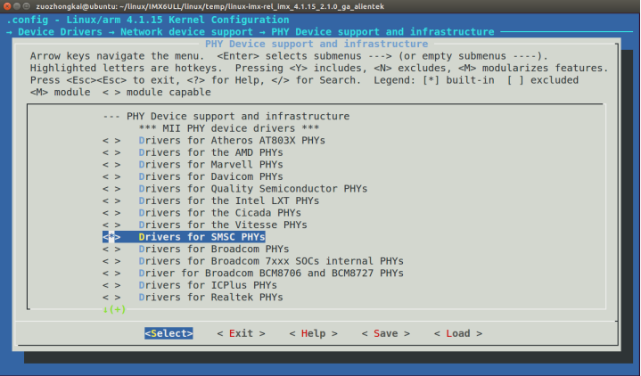
Figure 69.4.3.1 enable LAN8720A drive
Select "Drivers for SMSC PHYs" in figure 69.4.3.1, and then compile the kernel. This has been mentioned when explaining linux porting in section 37.4.3.
Open smsc.c and find the following contents (limited to space and deleted):
Example code 69.4.3.8 currency PHY drive
1   static struct phy_driver smsc_phy_driver[] = {
2   {
3       .phy_id     	= 0x0007c0a0, /* OUI=0x00800f, Model#=0x0a */
4       .phy_id_mask  	= 0xfffffff0,
5       .name       	= "SMSC LAN83C185",
......
24      .driver     	= { .owner = THIS_MODULE, }
25  }, {
26      .phy_id     	= 0x0007c0b0, /* OUI=0x00800f, Model#=0x0b */
27      .phy_id_mask 	= 0xfffffff0,
28      .name       	= "SMSC LAN8187",
......
47      .driver     	= { .owner = THIS_MODULE, }
48  }, {
49      .phy_id     	= 0x0007c0c0, /* OUI=0x00800f, Model#=0x0c */
50      .phy_id_mask 	= 0xfffffff0,
51      .name       	= "SMSC LAN8700",
......
70      .driver     	= { .owner = THIS_MODULE, }
71  }, {
72      .phy_id     	= 0x0007c0d0, /* OUI=0x00800f, Model#=0x0d */
73      .phy_id_mask 	= 0xfffffff0,
74      .name       	= "SMSC LAN911x Internal PHY",
......
92      .driver     	= { .owner = THIS_MODULE, }
93  }, {
94      .phy_id     	= 0x0007c0f0, /* OUI=0x00800f, Model#=0x0f */
95      .phy_id_mask 	= 0xfffffff0,
96      .name       	= "SMSC LAN8710/LAN8720",
97
98      .features   	= (PHY_BASIC_FEATURES | SUPPORTED_Pause
99                  		| SUPPORTED_Asym_Pause),
100     .flags      	= PHY_HAS_INTERRUPT | PHY_HAS_MAGICANEG,
101
102     /* basic functions */
103     .config_aneg 	= genphy_config_aneg,
104     .read_status 	= lan87xx_read_status,
105     .config_init 	= smsc_phy_config_init,
106     .soft_reset 	= smsc_phy_reset,
107
108     /* IRQ related */
109     .ack_interrupt 	= smsc_phy_ack_interrupt,
110     .config_intr    	= smsc_phy_config_intr,
111
112     .suspend    		= genphy_suspend,
113     .resume     		= genphy_resume,
114
115     .driver     		= { .owner = THIS_MODULE, }
116 } };
117
118 module_phy_driver(smsc_phy_driver);
From sample code 69.4.3.8 As you can see, smsc_phy_driver Still support a lot SMSC Homely PHY Chips, such as LAN83C185,LAN8187,LAN8700 Wait, of course, it must be included LAN8720 Series, No. 93~116 OK, that's it LAN8710/LAN8720 series PHY Drive.
Line 94, PHY ID Is 0 X0007C0F0.
Line 95, PHY of ID The mask is 0 XFFFFFFF0,That is, the first 28 bits are valid. During matching, only the first 28 bits need to be compared, and the fourth bit does not need to be compared.
In line 74, the driver name is "SMSC LAN8710/LAN8720". After the system starts, open the network card and you will be prompted that the current PHY driver name is "SMSC LAN8710/LAN8720".
Finally, line 118 uses module_phy_driver (essentially a macro) to complete the registration of smsc_phy_driver.
Some of the member functions in this driver are written by SMSC itself, and some are directly driven by general PHY, such as genphy_config_aneg in line 103, genphy_suspend in line 112, etc.
69.5 network driven test
69.5.1 LAN8720 PHY drive test
Firstly, it must be the driver modification. This has been explained in detail in section 37.4.3. Refer to the modification. After the system is started, the current PHY driver name will be printed as "SMSC LAN8710/LAN8720", as shown in figure 69.5.1.1:

Figure 69.5.1.1 network PHY drive information
As can be seen from figure 69.5.1.1, at this time, the PHY driver uses "SMSC LAN8710/8720". When we use the ifconfig command to open the network card, we will also prompt the name of the current PHY driver. As for the network test, it is very simple. You can ping the address of the host or ubuntu. If you can ping, it means that the network is working normally.
69.5.2 general PHY drive test
As we said earlier, according to the truth, the general PHY driver can certainly drive any PHY chip, but sometimes the society is so unreasonable. At the beginning, the author used the general PHY driver to drive the LAN8720. As a result, the reality taught the young author a lesson and failed! After searching, it is found that enet1 is required to use LAN8720 under I.MX6ULL_ TX_ CLK and enet2_ TX_ The configuration of these two pins of CLK, that is, FEC needs to be modified_ FEC in main. C file_ Probe function. See section 37.4.3 for details. After the modification, you can try to use the general PHY driver, which is not guaranteed to succeed! First configure the Linux kernel, close the LAN8720 driver, then recompile the Linux kernel and start it with a new Linux kernel.
After the system is started, the general PHY driver will be used, and the information shown in figure 69.5.1.2 will be output:

Figure 69.5.2.1 general PHY drive information
As can be seen from figure 69.5.2.1, the name of the network card driver is "Generic PHY", indicating that a general PHY driver is used.
69.5.3 DHCP function configuration
In our previous experiments, the IP address of the development board was manually set, but setting the IP address by ourselves is easy to conflict with the IP address of other devices in the network. The best way is to let the router automatically assign the IP address. The IP address assigned through the router must be unique in the network. We need to dynamically apply for IP address from the router through the udhcpc command. The udhcpc command has been integrated into busybox, so we don't need to transplant it separately.
In addition, we also need a file, otherwise directly using udhcpc to apply for IP address will fail. Find examples/udhcp/simple.script in the busybox source code and copy it to the / usr/share/udhcpc directory of the development board (if not, please create this directory yourself). After copying, rename simple.script in the root file system to default.script. The command is as follows:
cd busybox-1.29.0/examples/udhcp
cp simple.script /home/zuozhongkai/linux/nfs/rootfs/usr/share/udhcpc/default.script / / copy and rename
After that, you can use udhcpc to apply for an IP address for the specified network card. Specify which network card to apply for an IP address through the "- i" parameter, followed by the name of the network card to apply for an IP address. For example, here we take the ALPHA development board of punctual atom as an example to apply for an IP address for eth1 network card. The command is as follows:
ifconfig eth1 up / / open eth1 network card
udhcpc -i eth1 / / apply for an IP address for eth1 network card
The application process is shown in figure 69.5.3.1:
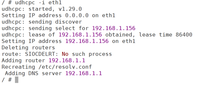
Figure 69.5.3.1 process of udhcpc applying for IP address
As can be seen from figure 69.5.3.1, the IP address requested by eth1 is 192.168.1.156, and the DNS server address in / etc/resolv.conf file is also modified. You can enter the "ifconfig" command to view the details of the eth1 network card, which will not be demonstrated here.
69.6 use of single network card
Sometimes in the actual product development, due to the limitation of the number of I.MX6ULL pins, some peripheral pins used conflict with the network card, but our product does not need two network cards. One is enough. At this time, it is necessary to modify the linux kernel to realize the use of one network card and the IO of another network card as other peripherals.
69.6.1 use only ENET2 network card
If only the ENET2 network card is used, the modification is relatively simple. Open the device tree imx6ull-alientek-emmc.dts. The node name corresponding to the ENET1 network card is fec1 and the node name corresponding to the ENET2 network card is fec2. We need to close the ENET1 network card, first find the fec1 node, and then change the status attribute to "disabled". The content of the fec1 node after modification is as follows
Example code 69.6.1.1 fec1 Node information
1 &fec1 {
2 pinctrl-names = "default";
3 pinctrl-0 = <&pinctrl_enet1
4 &pinctrl_enet1_reset>;
5 phy-mode = "rmii";
6 phy-handle = <ðphy0>;
7 phy-reset-gpios = <&gpio5 7 GPIO_ACTIVE_LOW>;
8 phy-reset-duration = <200>;
9 status = "disabled";
10 };
Line 9, replace status Change to“ disabled".
After modification, recompile the device tree and start the kernel with the new device tree. After the kernel starts, enter the following command to view all network cards in the current system:
ifconfig -a / / view all network cards
The results are shown in figure 69.6.1.1:
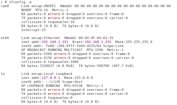
Figure 69.6.1.1 current system network card information
As can be seen from figure 69.6.1.1, at this time, as long as there is only one eth0 network card and there is no eth1, it indicates that fec1 is closed. Next, you can reuse the IO corresponding to fec1 network card for other peripheral functions.
69.6.2 use only ENET1 network card
If only the ENET1 network card is used, it will be a little more complicated. Instead of simply changing the status under the fec2 node to "disabled", follow the following steps to modify the device tree imx6ull-alientek-emmc.dts:
1. Mask or delete fec2 node content
First, mask or delete the content of fec2 node corresponding to ENET2 network card in imx6ull-alientek-emmc.dts file, as shown in figure 69.6.2.1:
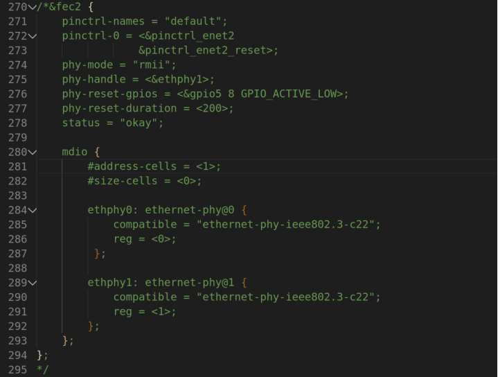
Figure 69.6.2.1 shielding fec2 node content
2. Modify the fec1 node information corresponding to ENET1.
Next, you need to modify the fec1 node. The focus is to add mdio child nodes under the fec1 node. The modified fec1 node is as follows:
Example code 69.6.1.2 Modified fec1 node
1 &fec1 {
2 pinctrl-names = "default";
3 pinctrl-0 = <&pinctrl_enet1
4 &pinctrl_enet1_reset>;
5 phy-mode = "rmii";
6 phy-handle = <ðphy0>;
7 phy-reset-gpios = <&gpio5 7 GPIO_ACTIVE_LOW>;
8 phy-reset-duration = <200>;
9 status = "okay";
10
11 mdio {
12 #address-cells = <1>;
13 #size-cells = <0>;
14
15 ethphy0: ethernet-phy@0 {
16 compatible = "ethernet-phy-ieee802.3-c22";
17 reg = <0>;
18 };
19 };
20 };
The point is fec1 Add section 11 to~19 OK mdio Child nodes, and only leave ENET1 Corresponding PHY Child nodes.
3,Mask or delete ENET2 Corresponding pinctrl node
 Delete after shielding ENET2 Corresponding pinctrl_enet2,As shown in Figure 69.6.2.2 As shown in:
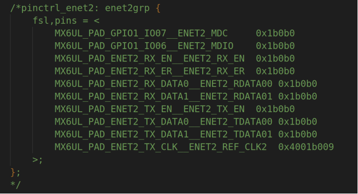
Figure 69.6.2.2 shielding pinctrl_enet2 node
4. Add MDIO and MDC pin configurations to the pinctrl node corresponding to the ENET1 network card
By default, GPIO1_IO07 and GPIO1_IO06 are multiplexed into the MDC and MDIO of ENET2. Therefore, we need to reuse GPIO1_IO07 and GPIO1_IO06 into the MDC and DMIO of ENET1. The modified pinctrl_enet1 content is as follows:
//Example code 69.6.1.3 modified pinctrl_enet1 node
1  pinctrl_enet1: enet1grp {
2   	fsl,pins = <
3       		MX6UL_PAD_GPIO1_IO07__ENET1_MDC     		0x1b0b0
4       		MX6UL_PAD_GPIO1_IO06__ENET1_MDIO    		0x1b0b0
5       		MX6UL_PAD_ENET1_RX_EN__ENET1_RX_EN  		0x1b0b0
6       		MX6UL_PAD_ENET1_RX_ER__ENET1_RX_ER  		0x1b0b0
7       		MX6UL_PAD_ENET1_RX_DATA0__ENET1_RDATA00 	0x1b0b0
8       		MX6UL_PAD_ENET1_RX_DATA1__ENET1_RDATA01 	0x1b0b0
9       		MX6UL_PAD_ENET1_TX_EN__ENET1_TX_EN  		0x1b0b0
10      	MX6UL_PAD_ENET1_TX_DATA0__ENET1_TDATA00 	0x1b0b0
11      	MX6UL_PAD_ENET1_TX_DATA1__ENET1_TDATA01 	0x1b0b0
12      	MX6UL_PAD_ENET1_TX_CLK__ENET1_REF_CLK1  	0x4001b009
13  	>;
14 };
Line 3, add GPIO1_IO07 Reuse as ENET1_MDC Pin.
Line 4, add GPIO1_IO06 Reuse as ENET1_MDIO Pin.
At this point, the device tree modification is completed, recompile the device tree, and then start the system with the new device tree. After startup, enter the following command to view all network card information on the development board:
ifconfig -a
The results are shown in figure 69.6.2.3:
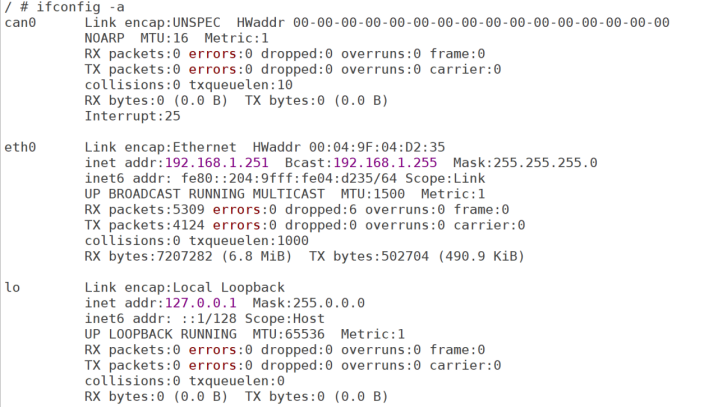
Figure 69.6.2.3 development board network card information
It can be seen from figure 69.6.2.3 that there is only one eth0 network card in the whole system. Note! The eth0 network card here is ENET1. Don't confuse it with the previous one. Think that eth0 is the name of ENET2 network card.
So far, the network driver of Linux is more complex, but it is really very simple to use in practice. Especially for this network scheme with built-in MAC + external PHY, we hardly need to modify the driver, because the kernel has inherited the general PHY driver.