catalogue
1, Title Requirements
The circuit is built with STM32 minimum system core board (STM32F103C8T6) + panel board + 3 red, green and blue LEDs. The three ports of GPIOB, GPIOC and GPIOD are used to control the LED lights to flash in turn, with an interval of 1 second.
Experimental equipment:
- One stm32 core board 103f
- usb to serial port
- One bread board and several wires
Experimental environment:
- Keil uVision 5
- MCU ISP burning software
- CH34_Install_Windows_v3_4
The installation package of mcuisp is as follows (extraction code: h2xc):
 https://pan.baidu.com/s/1WyvtnCJad_BqXbwTzhcofw
2, Establishment of project
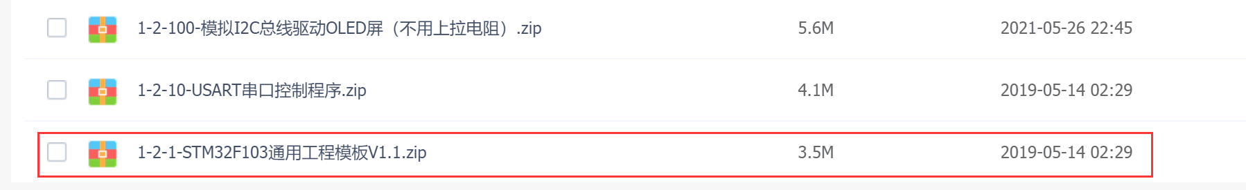
Here we refer to the students' blog and use the ready-made project template, as follows:
http://www.doyoung.net/YT/xx3.html http://www.doyoung.net/YT/xx3.html Click open and select the following folder to download. After downloading, unzip it to the current folder
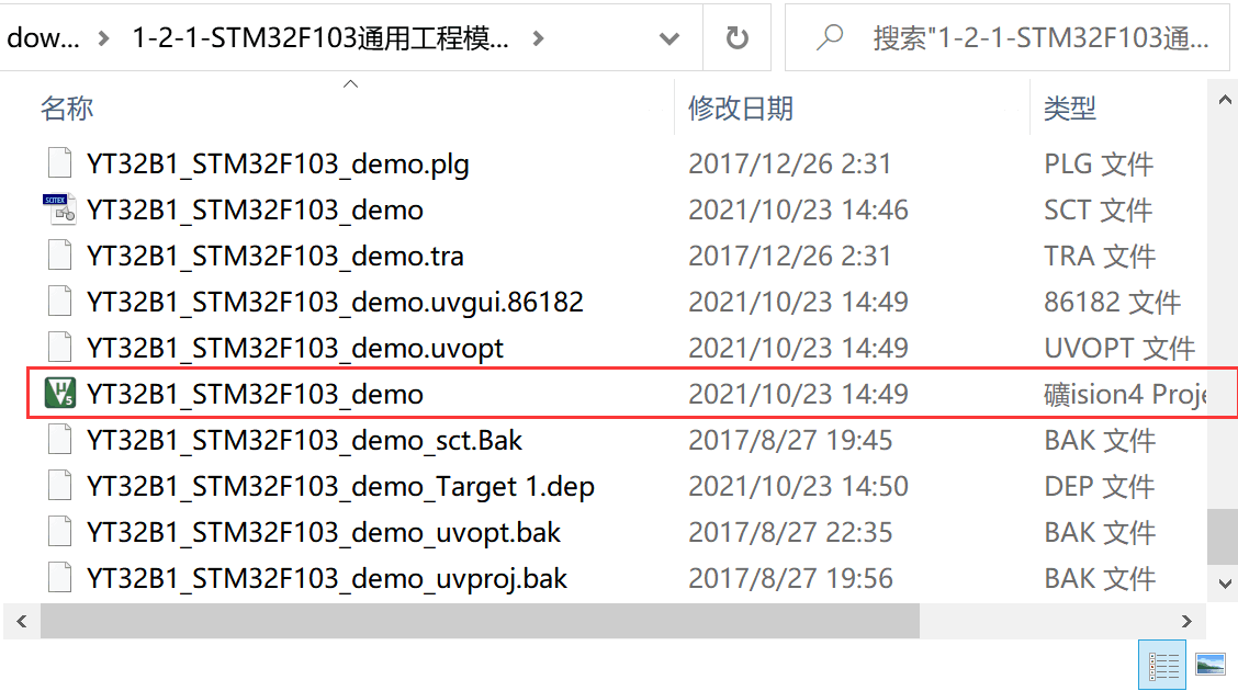
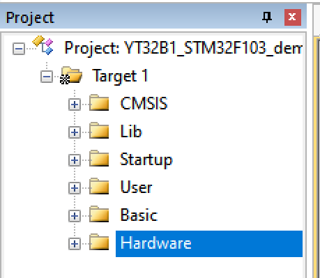
You can find a keil project in the extracted folder. Open it in keil uVision 5 to find folders with different functional partitions, as shown in the following figure:
3, Programming
1) Circuit diagram
The following is the circuit diagram of LED lamp connected with stm32 single chip microcomputer
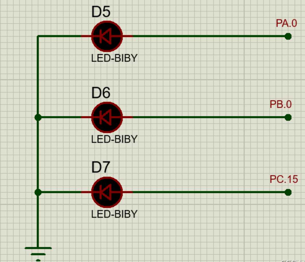
Note: during physical connection, the longer end of led lamp is connected to stm32 plate and the shorter end is connected to negative electrode, as shown in the figure above.
2) Code writing
① Initialize the pin and create a file: led.c as follows:
#include "led.h"

void LED_Init(void){ //LED lamp interface initialization

 GPIO_InitTypeDef  GPIO_InitStructure;

 RCC_APB2PeriphClockCmd(RCC_APB2Periph_GPIOA, ENABLE);	 //Turn on the clock
 GPIO_InitStructure.GPIO_Pin = GPIO_Pin_0;				 //Initialization pin
 GPIO_InitStructure.GPIO_Mode = GPIO_Mode_Out_PP; 		 //Set output mode, push-pull output mode
 GPIO_InitStructure.GPIO_Speed = GPIO_Speed_50MHz;		//Set output rate
 GPIO_Init(GPIOA, &GPIO_InitStructure);
 GPIO_ResetBits(GPIOA,GPIO_Pin_0);					//Define the initial value of this pin as low level

 RCC_APB2PeriphClockCmd(RCC_APB2Periph_GPIOB, ENABLE);
 GPIO_InitStructure.GPIO_Pin = GPIO_Pin_0;
 GPIO_InitStructure.GPIO_Mode = GPIO_Mode_Out_PP;
 GPIO_InitStructure.GPIO_Speed = GPIO_Speed_50MHz;
 GPIO_Init(GPIOB, &GPIO_InitStructure);
 GPIO_ResetBits(GPIOB,GPIO_Pin_0);

 RCC_APB2PeriphClockCmd(RCC_APB2Periph_GPIOC, ENABLE);
 GPIO_InitStructure.GPIO_Pin = GPIO_Pin_15;
 GPIO_InitStructure.GPIO_Mode = GPIO_Mode_Out_PP;
 GPIO_InitStructure.GPIO_Speed = GPIO_Speed_50MHz;
 GPIO_Init(GPIOC, &GPIO_InitStructure);
 GPIO_ResetBits(GPIOC,GPIO_Pin_15);
}
Since the initialization function led in led.c needs to be called in the subsequent file_ Init (void), so we need to create a header file led.h to declare this function and then call it.
#include "stm32f10x.h"
void LED_Init(void);//initialization
Save the above two files to the folder where you first unzipped them, so that you can find them later;
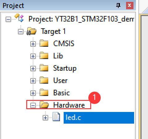
Click the hardware folder in the project bar to add the led.c file just saved
Next, process the main function in the main.c file. Since it is necessary to call the LED initialization function, it is necessary to call the led.h header file created above, and add the LED initialization function to the main file. The specific code of the changed main.c file is as follows:
#include "stm32f10x.h"
#include "delay.h"
#include "led.h"


int main (void){//main program
	RCC_Configuration(); //Clock setting
	LED_Init();
	while(1){
	  GPIO_SetBits(GPIOA,GPIO_Pin_0);	//This is to set the IO port to high level, which is 3.3V
	  delay_ms(500);
    GPIO_ResetBits(GPIOA,GPIO_Pin_0);//This is to set the IO port to low level, which is 0V
    delay_ms(500);
    GPIO_SetBits(GPIOB,GPIO_Pin_0);	//This is to set the IO port to high level, which is 3.3V
    delay_ms(500);
		GPIO_ResetBits(GPIOB,GPIO_Pin_0);//This is to set the IO port to low level, which is 0V
    delay_ms(500);
    GPIO_SetBits(GPIOC,GPIO_Pin_15);	//This is to set the IO port to high level, which is 3.3V
    delay_ms(500);
		GPIO_ResetBits(GPIOC,GPIO_Pin_15);//This is to set the IO port to low level, which is 0V
    delay_ms(500);
	}
}
GPIO_SetBits(GPIOX,GPIO_Pin_x). This function means to set the pin to high level;
GPIO_ResetBits(GPIOX,GPIO_Pin_x). This function means to set the pin to low level;
3) Simulation Implementation
First compile the engineering code and set the simulator without error;
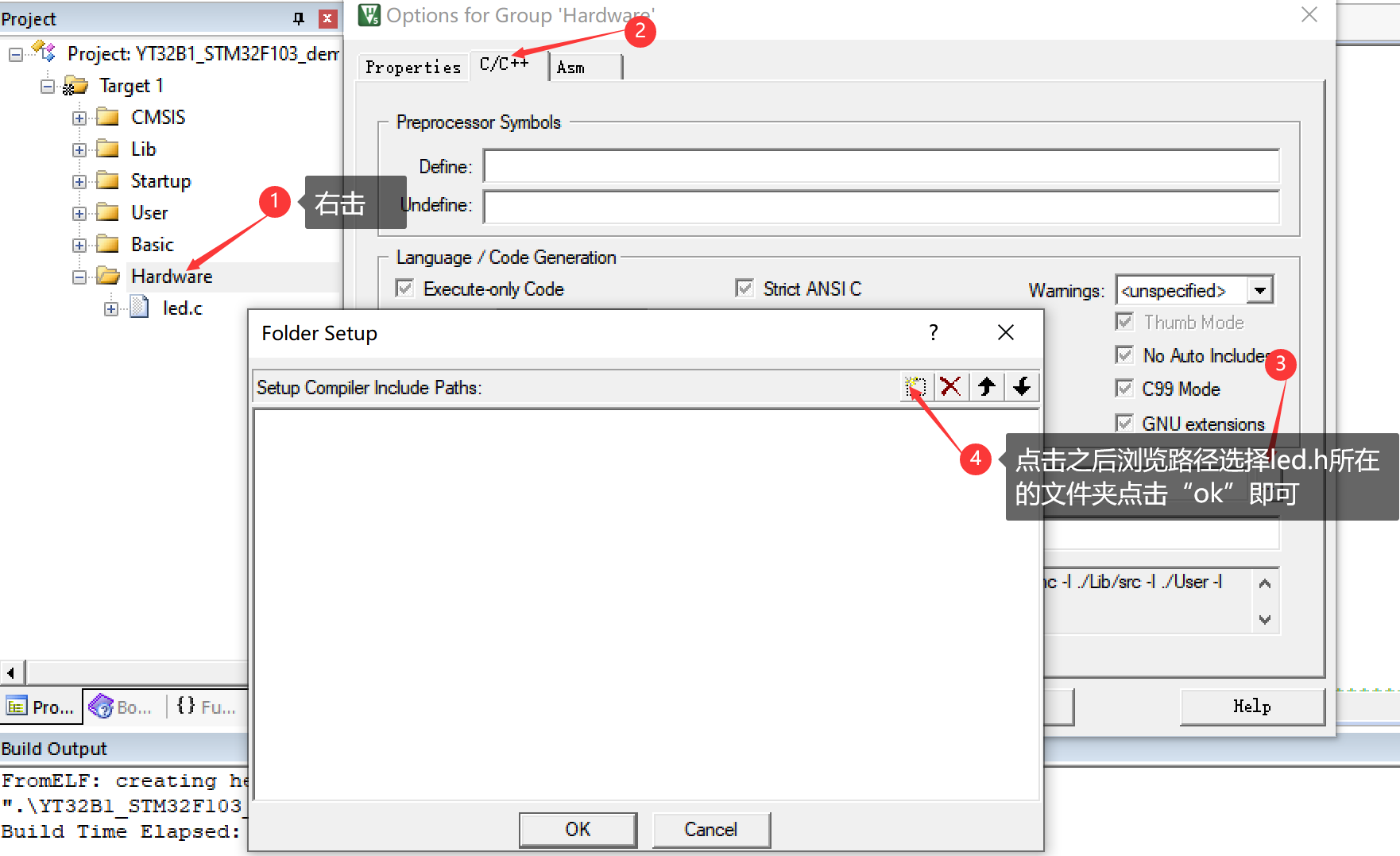
Here is the solution if there is an error and the error shows that the led.h file cannot be found:
After the compilation is successful again, the simulator can be set;
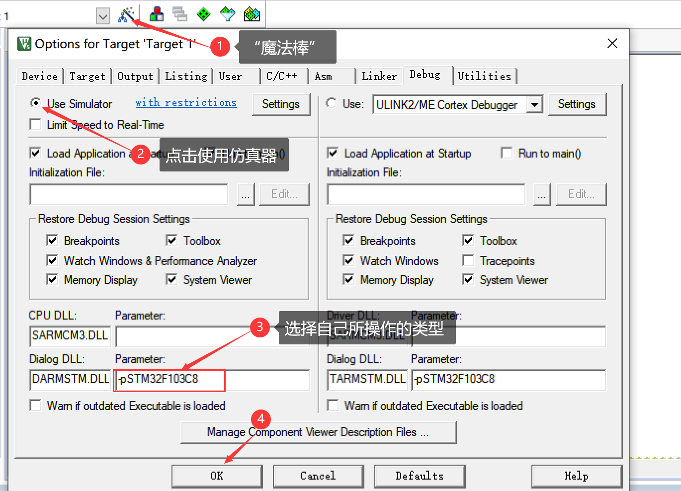
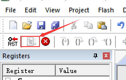
First, click the "magic wand icon" and perform the following operations on the Debug page:
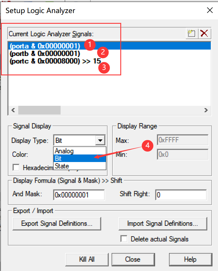
Next, conduct simulation. After clicking simulation, first select the waveform type we want to display - square wave, and then add the discipline number to be viewed in the logic window (click setup), as follows:
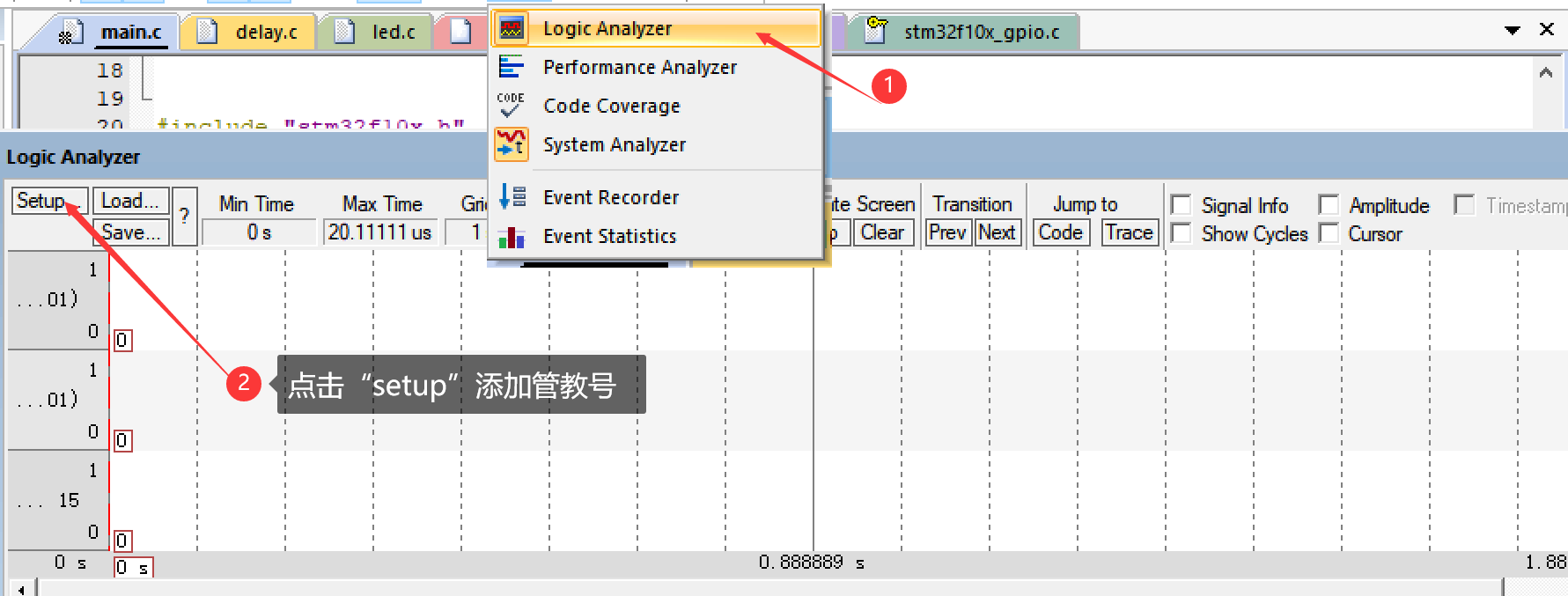
Add discipline number: manually enter the following discipline numbers in turn, set the Display Type to bit type, and then click close (you can also click color to select the color of the waveform);
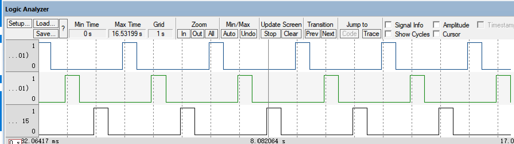
Then start the simulation and observe the waveform:
4, Program burning
1) Connection steps
First, insert stm32 chip into bread board;
Before connecting stm32 chip and USB TTL, first observe the pins of the two devices:
For USB-TTL, USB-TTL has five pins, namely 5V power pin, 3.3V power pin, TXD (data transfer) pin, RXD (data reception) pin and GND pin
The specific connection method is:
PA9---RXD
PA10---TXD
The grounding port "G" of stm32 is connected to the cathode (negative pole) of bread board. The connection mode of LED lamp has been mentioned above
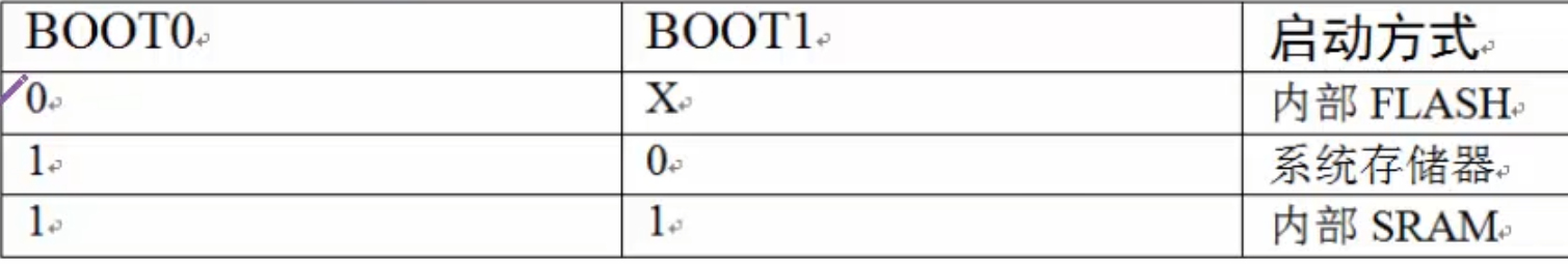
There is also the BOOT configuration of the development board. Set the jumper cap on the board as follows, indicating that it is converted to the system memory mode
BOOT0->1 BOOT1->0
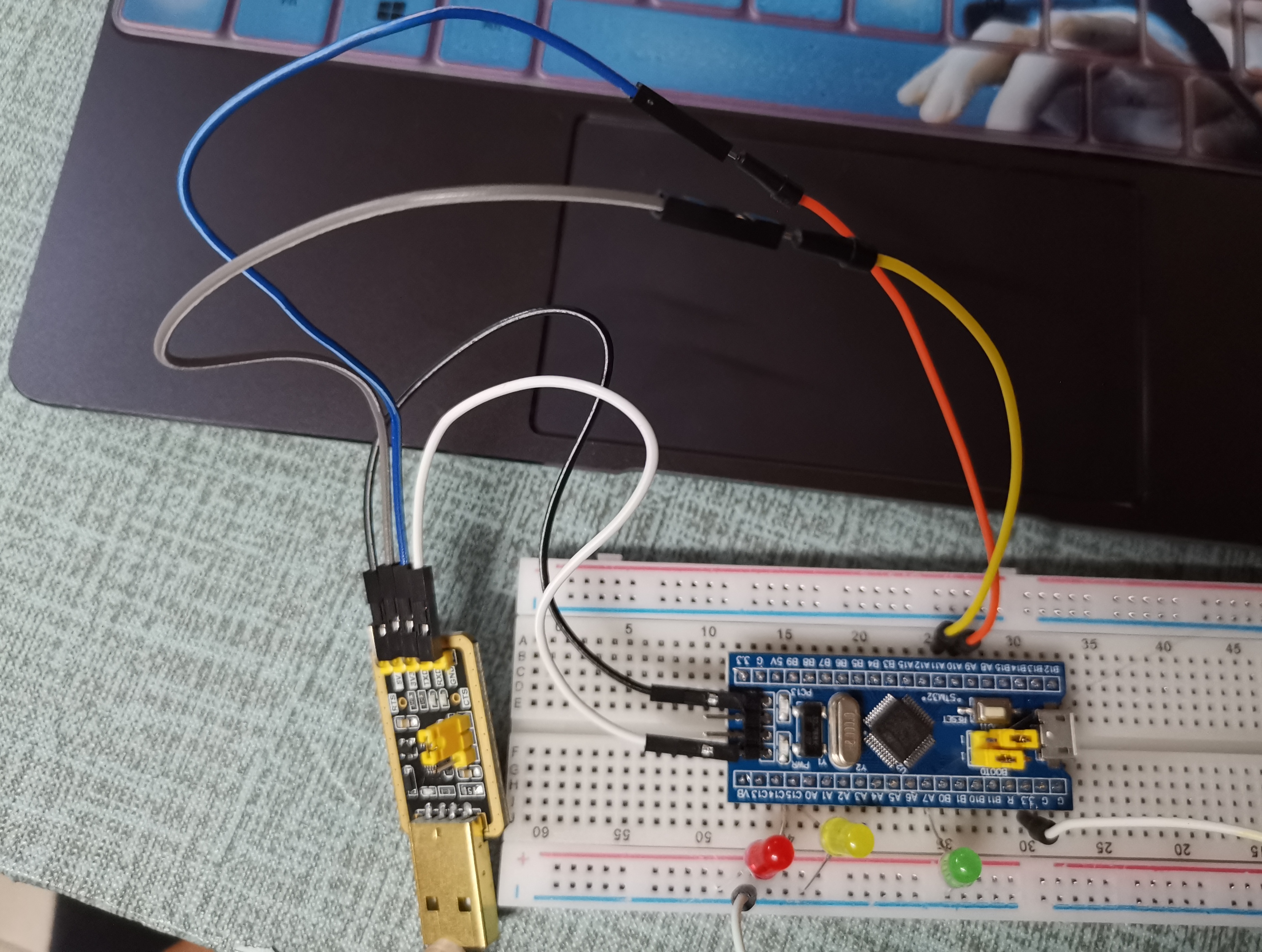
 See the actual drawing for specific connection:
2) Burning program
First, connect the USB-TTL interface to our computer and download CH34_Install_Windows_v3_4. After installation, right-click the computer - > more - > Management - > Device Manager - > port, and you can find the port we access:

Next, open the mcuisp software and configure as follows. Here, my computer port is COM3, as long as it is the same as that in your device manager. The specific configuration is as follows:
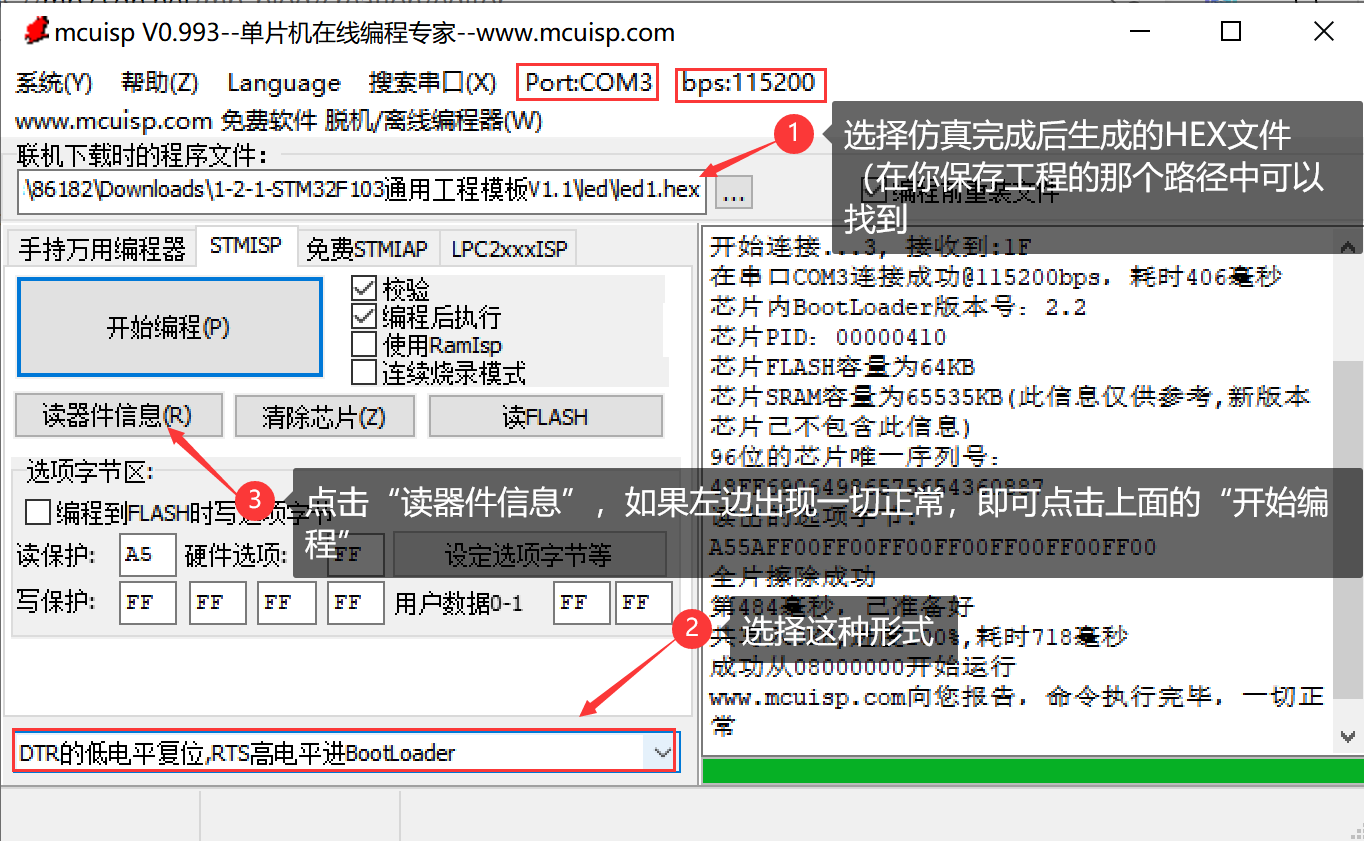
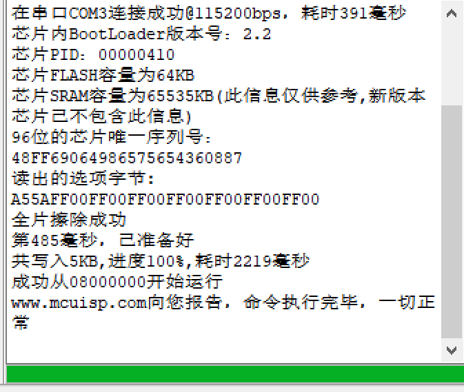
Start burning!!!!
5, Result display
6, Summary
The experiment of running water lamp is a great challenge for me, a novice. Due to my unskilled knowledge of single chip microcomputer, I don't understand many operations, but fortunately with the help of my classmates. Basically, all problems can be solved. If there are any inappropriate words in the article, please point out!!! Please see the reference section for more details!!!
7, Reference content
1,(4 messages) STM32 minimum core board F103 serial communication USART_ vic_ to_ CSDN blog
2, (4 messages) make water lamp with STM32F103C8T6_ txmnQAQ blog - CSDN blog