
Introduction: A preliminary test is carried out for the given micro Python porting version. In contrast, many modules in MCU have not been supported. These tasks need to be completed as soon as possible in the near future.
Key words: MM32, micro Python
§ 01 micro Python development
1, Background introduction
in order to be able to National college student smart car competition Based on MicroPython The development mode is suitable for students with non electronic professional background to participate in the exercise of smart car competition. In fact, in previous competitions, OpenMV and OpenART modules based on NXP have adopted the micro Python development mode, but these modules can not provide more ports to meet the development of smart car competition model works.
1. Hardware module
the following is the development module based on smart single chip microcomputer MM32F3277 provided by zhufei technology, which has preliminarily inhibited the micro Python environment.
in Debugging MM32F3277 from zhufei, transplanted with micro Python development board This paper introduces the relevant information of the development board, and establishes a tool chain for interactive development through REPL.
2. Development mode
utilization STM32 Bootloader The software forms the REPL interactive interface of micropathon, and the micropathon program on the clipboard can be downloaded to MM32 for direct. At the same time, the information output by REPL can be displayed.
2, Development board hardware
1. Operating instructions of test board
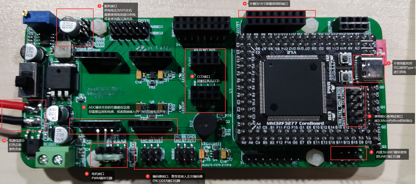
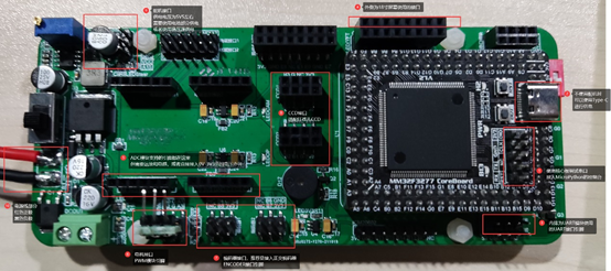
the following is the hardware operation instructions of the development version sent by zhufei technology.
Test preparation:
connect a normal motherboard. The Board sent has been connected to the screen and inserted into the SD card;
please use battery or regulated source to supply power from the power line. The recommended voltage is 8V (more than 6V).
or Type-C on the black core board can be used for power supply, but the steering gear can not be connected when only Type-C is used for power supply.
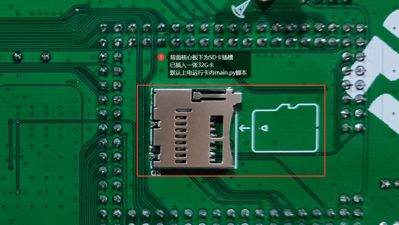
on the back is the SD card socket, which has been connected to the SD card. When powered on, the main.py in the card runs by default. The phenomenon is that the LED on the black core board flashes.
Connection and environment settings:
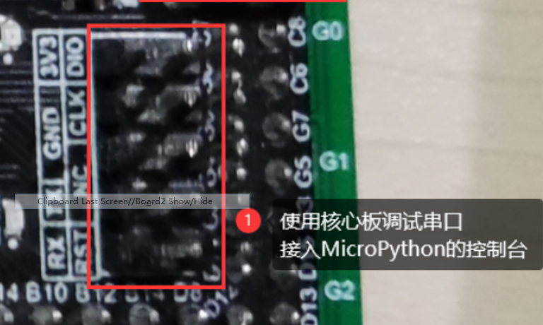
the serial port is connected to the serial port of the download and debugging interface of the black core board. The baud rate is 115200. After power on, RPEL interaction is carried out here. It should be noted that if there is main.py in the SD card, main.py will be run first:
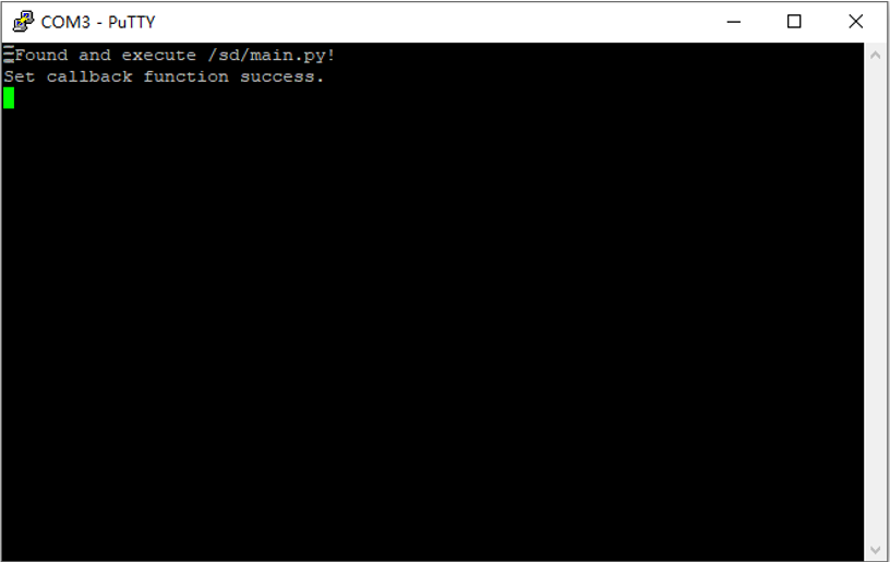
at this time, the main.py file in the SD card is running. The Python program in the attached SD card is not set to exit, so it cannot enter RPEL.
you need to delete the main.py in the SD card or delete the file cyclically. Here, we choose to delete the file, insert the card again and reset:
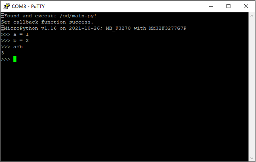
at this time, enter RPEL and output the micro Python version.
Try Python statement execution:
based on the attached sample py file, you can try to run the display effect
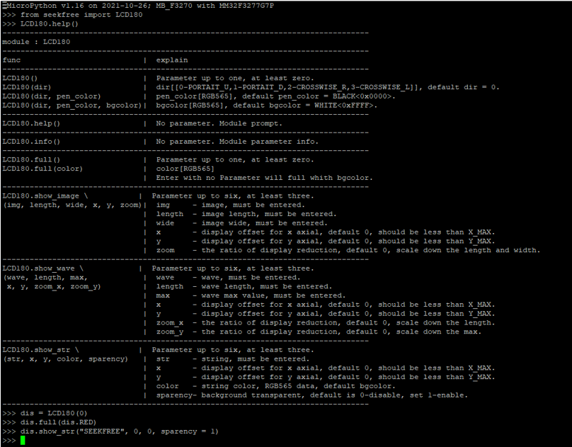
run the above statement, the corresponding LCD screen will be refreshed to full screen red and the word SEEKFREE will be displayed.
2. Schematic diagram of experimental board
the principle can be downloaded from the following link: Schematic diagram of MM32F3277 motherboard
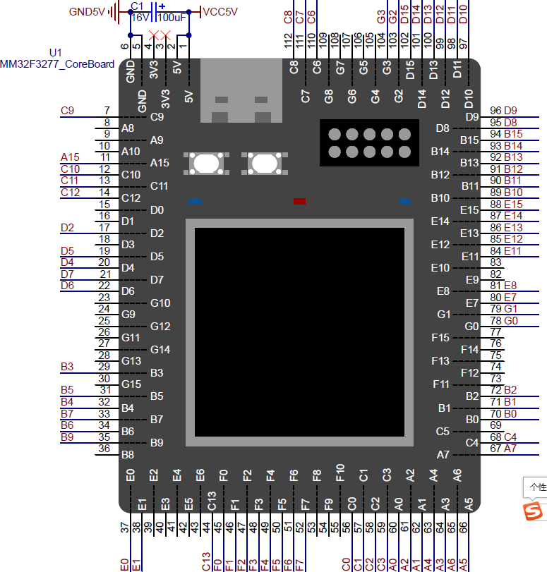
(1) Core motherboard
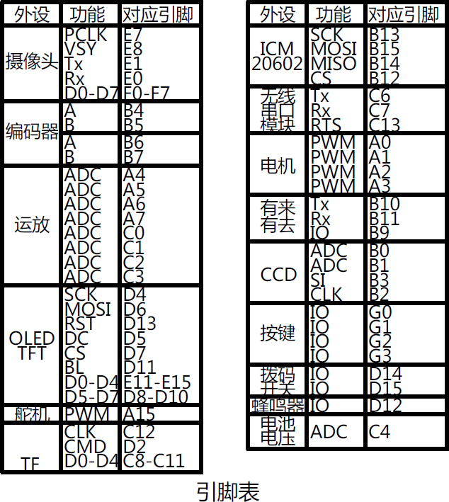
(2) Backplane function definition
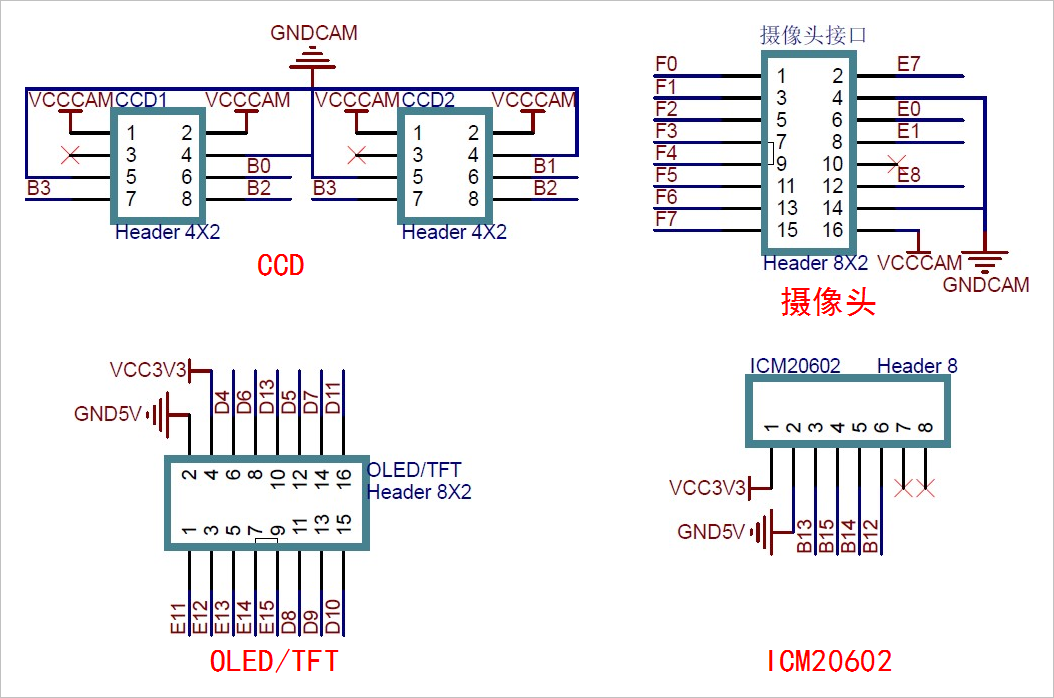
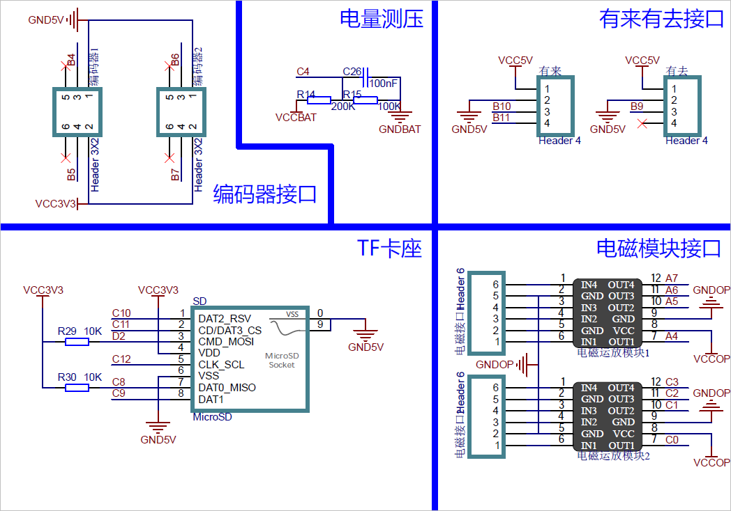
(3) Backplane sub circuit diagram
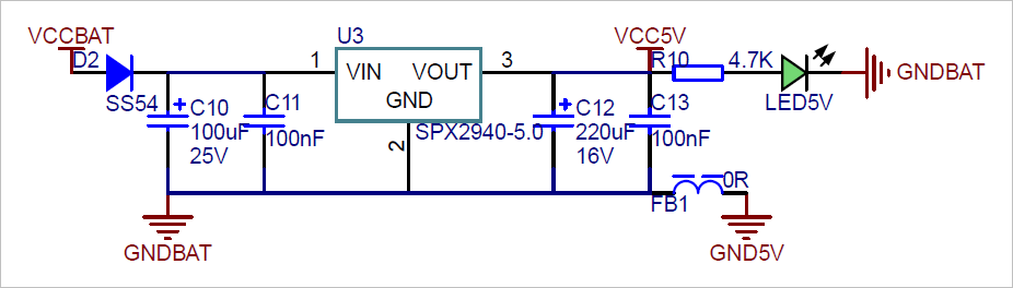
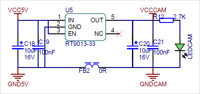
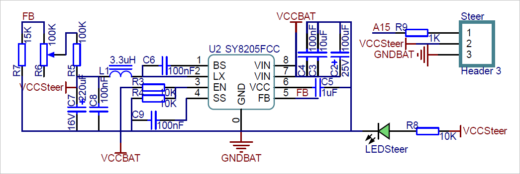
there are three 3.3V power supplies on the circuit board to provide general 3.3V, camera and operational amplifier power respectively.
3, Micro Python features
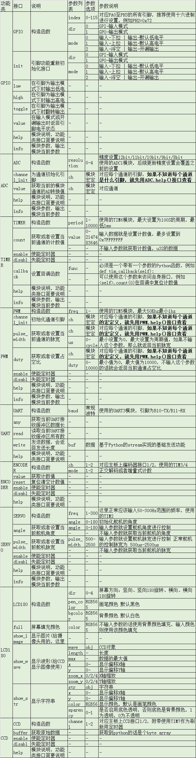
the following are the micro Python functions that have been ported in MM32F3277. This paper makes a preliminary test on these functions.
§ 02 functional test
1, GPIO test
1. GPIO output
(1) Test code
from seekfree               import GPIO

pinpg1 = GPIO(0x67, 1, 1)

print("Test GPIO .")
while True:
    pinpg1.low()
    pinpg1.high()
(2) Test results
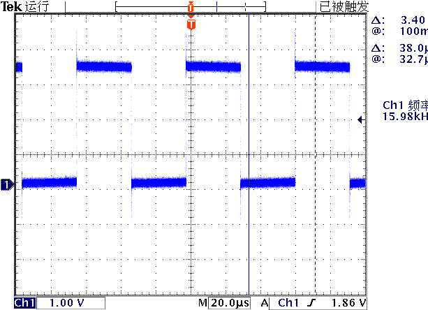
use an oscilloscope to measure the G7 pin waveform of MM32 module.
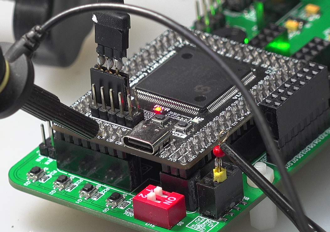
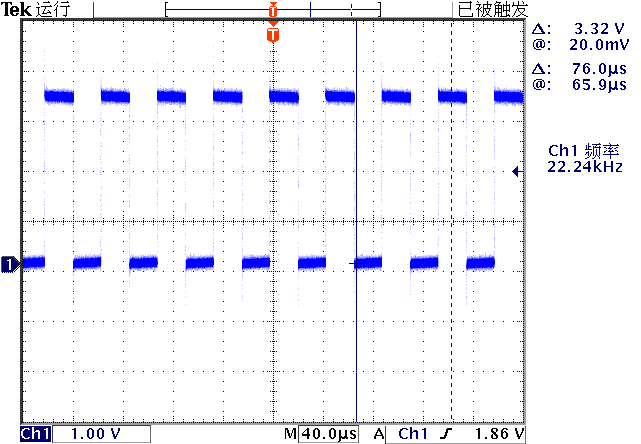
through the above test, it can be seen that the cycle of port operation under microphoton is about 22.28 μ s \mu s μs.
Because the code is ultimately a dead loop, it needs to be reset by MM32 before it can be transferred from the dead loop.
(3) Modify debug port
in order to control MM32 reset from software, NRST control line is added to the original debugging port.
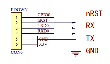
MM32 reset process is added to the MPDLD command of STM32.
if(strncmp(szString, "MPDLD", 5) == 0) {   // MicroPython Dlownload
    char szString[0x8000];

    strcpy(szString, "");
    Clipboard()->GetTextBuf(szString, sizeof(szString) - 1);

    ClearInfor();
    ShowInfor("Reset MicroPython...");
    RTSEnable(1, PORT1);
    Sleep(50);

    ClearPort(PORT1);
    RTSEnable(0, PORT1);
    Sleep(100);

    ShowInfor("Wait for MicroPython comeback...");
    for(;;) {
        char c;
        if(ReceChar(&c, PORT1) == 0) break;
    }

    int nLength = strlen(szString);
    int i;

    int nLine = 0;
    for(i = 0; i < nLength; i ++) {
        if(szString[i] == '\r') nLine ++;
    }

    char szTemp[512];
    sprintf(szTemp, "Download MicroPython : %d lines/%d characters.", nLine, nLength);
    ShowInfor(szTemp);
    ShowInfor("Begin to download programm...");
    Sleep(100);

    MessageBeep(0);
    SendChar(0x2, PORT1);       // Send CTRL+B
    Sleep(100);
    SendChar(0x5, PORT1);       // Send CTRL+A
    Sleep(100);

    for(i = 0; i < nLength; i ++) {
        ProgressBar1->Position = (i + 1) * 100 / nLength;
        SendChar(szString[i], PORT1);
    }

    for(;;) {
        char c;
        if(ReceCharL(&c, PORT1, 20) > 0) break;
    }

    ShowInfor("-------------------------------------------------------------------------");
    SendChar(0x4, PORT1);      // Send CTRL+B

    return;
}
after modification, it is also convenient to automatically download the program for the circular program.
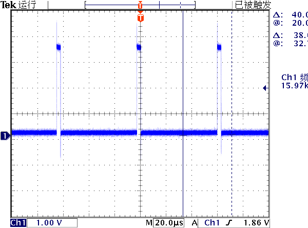
(4) Test toggle
from seekfree               import GPIO

pinpg1 = GPIO(0x67, 1, 1)

print("Test GPIO .")
while True:

    pinpg1.toggle()
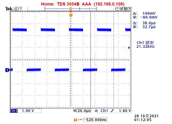
from the above waveform, the running time of toggle() is slightly slower than that of low(), high().
2,LED
now there is no time module in the module. This module can provide delay operation. Therefore, the interval can only be realized by software delay.
lead out C6,C7,GND,+5V in the wireless serial port HEADER, and test the GPIO output control LED.
from seekfree               import GPIO

led1 = GPIO(0x26, 1, 1)
led2 = GPIO(0x27, 1, 0)

print('Test LED.')

while True:

    def delay(loop):
        for _ in range(loop):
            pass

    led1.high()
    led2.low()
    delay(20000)
    led1.low()
    led2.high()
    delay(20000)
3. Test button
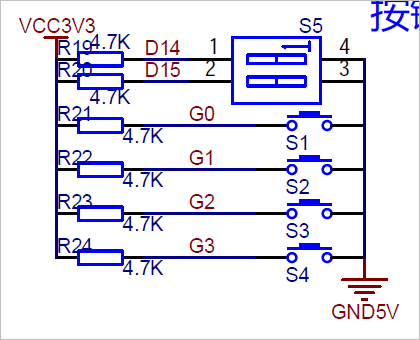
(1) Hardware
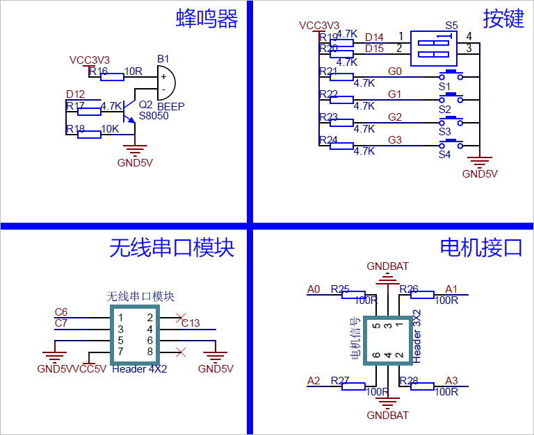
as shown in the previous hardware circuit diagram, four keys are integrated on the circuit board: G0, G1, G2 and G3. Their corresponding ports are: GPIOG0, G1,G2,G3.
(2) Test software
from seekfree               import GPIO

led1 = GPIO(0x26, 1, 1)
led2 = GPIO(0x27, 1, 0)

btn1 = GPIO(0x60, 0, 1)
btn2 = GPIO(0x61, 0, 1)
btn3 = GPIO(0x62, 0, 1)
btn4 = GPIO(0x63, 0, 1)

print('Test LED.')

def delay(loop=50000):
    for _ in range(loop):
        pass

while True:
    print([btn1.value(), btn2.value(), btn3.value(), btn4.value()])
    delay(50000)
4. Test dial switch
there are two dialing switches on the circuit board, corresponding to D14 and D15 respectively. Their status can be read out through GPIO. The test method is the same as the above keys.
from seekfree               import GPIO

print('Test LED.')
def delay(loop=50000):
    for _ in range(loop):
        pass

led1 = GPIO(0x26, 1, 1)
led2 = GPIO(0x27, 1, 0)

btn1 = GPIO(0x60, 0, 1)
btn2 = GPIO(0x61, 0, 1)
btn3 = GPIO(0x62, 0, 1)
btn4 = GPIO(0x63, 0, 1)

sw1 = GPIO(0x3e, 0, 1)
sw2 = GPIO(0x3f, 0, 1)

while True:
    print([btn1.value(), btn2.value(), btn3.value(), btn4.value(), sw1.value(), sw2.value()])
    delay(50000)
2, ADC test
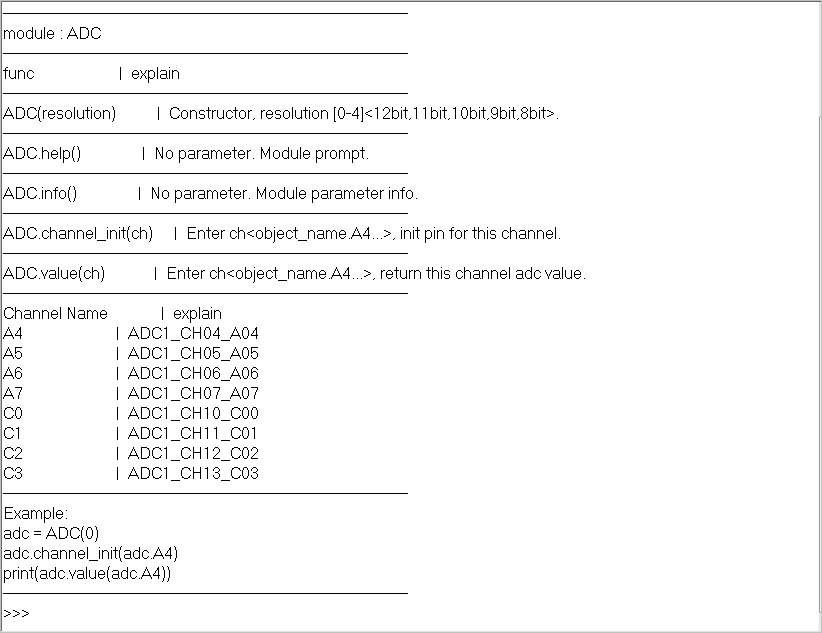
1,ADC.help()
2,adc.value()
lead the of the electromagnetic module interface to the bread board, use the potentiometer to obtain different voltages and send them to A4.

variance of data: 5.
because microphoton does not support floating-point operations. Therefore, it is necessary to use the shaping number to complete the relevant calculation.
from seekfree               import ADC,GPIO

adc = ADC(0)
adc.channel_init(adc.A4)

print('Test ADC.')

def delay(loop=50000):
    for _ in range(loop):
        pass

def sqrt(x):
    left = 0
    right = x//2+1
    while left < right:
        middle = left + (right-left+1)//2
        square = middle * middle

        if square > x:
            right = middle-1
        else: left = middle

    return left

SAMPLE_NUM = 1024
adcdim = [0]*SAMPLE_NUM

for i in range(SAMPLE_NUM):
    adcdim[i] = adc.value(adc.A4)

print(adcdim)

count = 0
for s in adcdim:
    count += s

average = count//SAMPLE_NUM

sigma = 0
for s in adcdim:
    ss = s - average
    sigma += ss**2

print(sqrt(sigma//SAMPLE_NUM))
3, PWM test
the PWM on the test version is output through A0, A1, A2 and A3 respectively.
1. Basic test
from seekfree               import PWM,GPIO

pwm = PWM(16000)
pwm.channel_init(pwm.A0, 5000)

print("Test PWM")
- duty = 5000
 ▲ figure 2.3.1 A0 output PWM waveform
- duty = 500
2. Changing PWM with ADC
from seekfree               import PWM,GPIO,ADC

pwm = PWM(16000)
pwm.channel_init(pwm.A0, 500)

adc = ADC(0)
adc.channel_init(adc.A4)

def delay(loop=50000):
    for _ in range(loop):
        pass

print('Test PWM...')
while True:
    adcvalue = adc.value(adc.A4)
    pwmvalue = adcvalue*10000//0x1000
    print(adcvalue, pwmvalue)
    pwm.duty(pwm.A0, pwmvalue)

    delay(10000)
after averaging the collected ADC, the waveform is very stable when PWM is controlled.
from seekfree               import PWM,GPIO,ADC

pwm = PWM(16000)
pwm.channel_init(pwm.A0, 5000)

adc = ADC(0)
adc.channel_init(adc.A4)

def delay(loop=50000):
    for _ in range(loop):
        pass

print('Test PWM...')

while True:

    sigma = 0
    for i in range(256):
        sigma  += adc.value(adc.A4)

    adcvalue = sigma//256
    pwmvalue = adcvalue*10000//0x1000

    pwm.duty(pwm.A0, pwmvalue)

    delay(1000)
4, Timer test
1. Basic test
set the callback function of the timer.
from seekfree               import TIMER,GPIO

led1 = GPIO(0x26, 1, 1)
led2 = GPIO(0x27, 1, 0)

def timer_callback(s):
    led1.toggle()
    print(s.count())

tim = TIMER(200)
tim.callback(timer_callback)

while True:
    pass
※ test summary ※
preliminary tests were conducted on the microphoton porting version of MM32. You can also see that the migration of this version needs to be enriched.
- Lack of support for SPI, I2C and CAN buses.
- Lack of support for floating point operations;
- Lack of support for SD card file access;
the above functions need to be further improved through later supplement.
■ links to relevant literature:
- Jiao Gao Si Gong Han [2005] No. 201 and Jiao Gao Si [2005] No. 13 related to smart car competition
- MicroPython
- Debugging MM32F3277 from zhufei, transplanted with micro Python development board
- STM32 Bootloader
- Schematic diagram of MM32F3277 motherboard
● relevant chart links:
- Figure 1.1.1 basic modules sent by flight
- Figure 1.2.1 front of development board hardware
- Figure 1.2.2 SD card slot behind the development version
- Figure 1.2.3 Download Interface of development board debugging port
- Figure 1.2.4 PuTTY interface of serial port terminal
- Figure 1.2.5 entering REPL for debugging
- Figure 1.2.6 results after running LCD180.help()
- Figure 1.2.7 core motherboard pin definition
- Figure 1.2.8 definition of backplane interface
- Figure 1.2.9 schematic diagram of 5V power supply
- Figure 1.2.10 camera 3.3V power supply
- Figure 1.2.11 steering gear power supply
- Figure 1.2.12 definition of some interface pins
- Figure 1.2.13 definition of some interface pins
- Figure 1.2.14 definition of some interface pins
- Figure 1.3.1 now ported micro Python accessibility
- Figure 2.1.1 measuring G7 pin waveform of MM32 module with oscilloscope
- Figure 2.1.2 output waveform of G7 port
- Figure 2.1.3 modify debugging port and add RST control port
- Figure 2.1.4 output waveform corresponding to toggle() function
- Figure 2.1.5 LED delay flashing
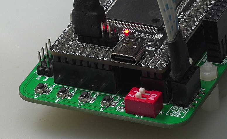
- Figure 2.1.6 keys and switches on the circuit board
- Figure 2.1.7 four keys on the development board
- Figure 2.1.8 measurement keys and dial switches
- Figure 2.2.1 ADC.help() display information
- Figure 2.2.2 1024 ADC values collected
- Figure 2.3.1 A0 output PWM waveform
- Figure 2.3.2 A0 output PWM waveform
- Figure 2.3.3 jitter PWM
- Figure 2.3.4 changing PWM duty cycle through ADC