I haven't updated my blog for a long time. I recently tested a relatively used Node. I'll share it with you here.
In engineering projects, sometimes a screen needs to display multi-channel camera data. After browsing the SDK development package officially provided by TI, I found a relatively simple Demo.
I use ti-processor-sdk-rtos-j721e-evm-08_00_00_12. You can download this development package on TI's official website. I won't repeat it here. If you have questions, you can confide in me. Later, you can sort out a more detailed blog from download to compilation.
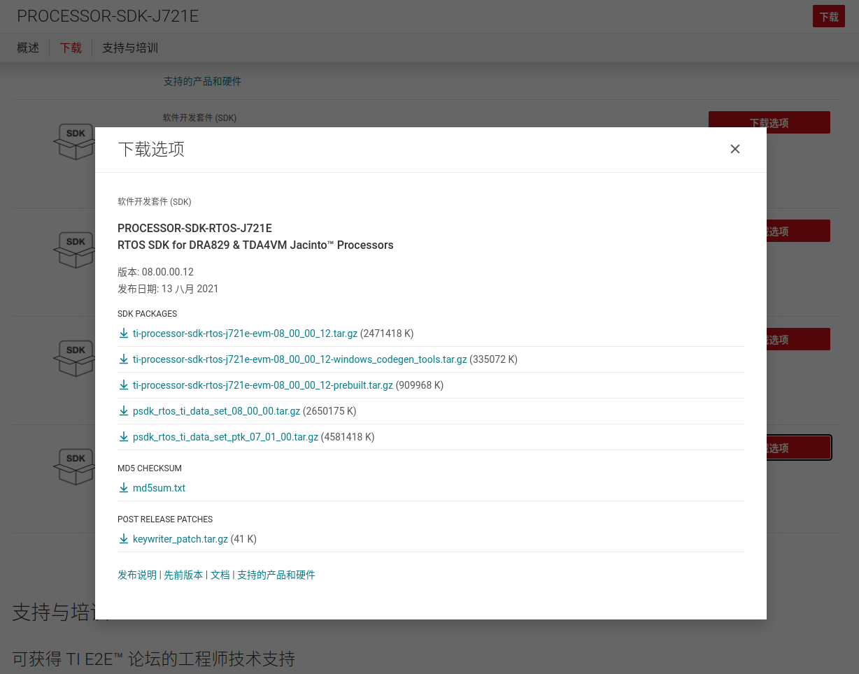
TDA4 SDK download address https://www.ti.com.cn/tool/cn/PROCESSOR-SDK-J721E?keyMatch=TDA4
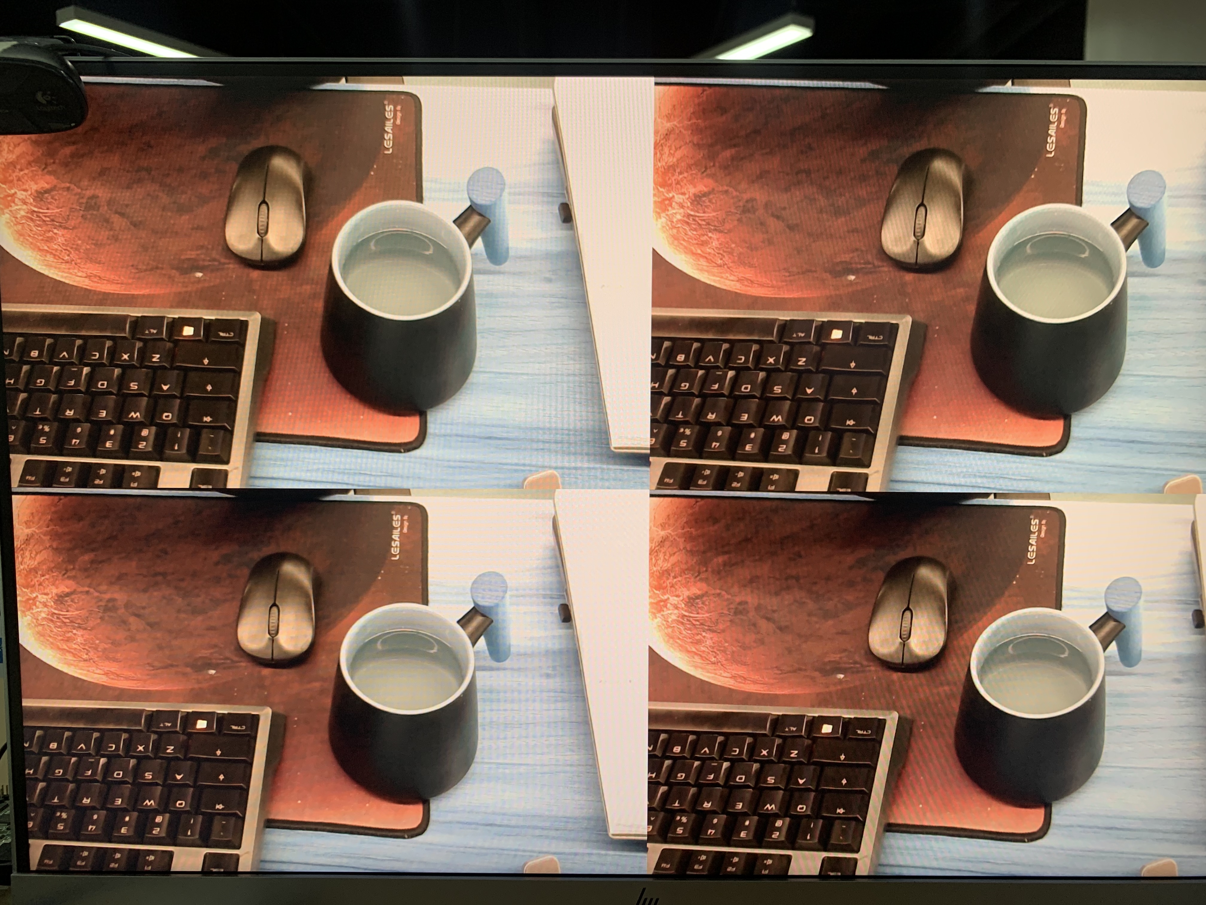
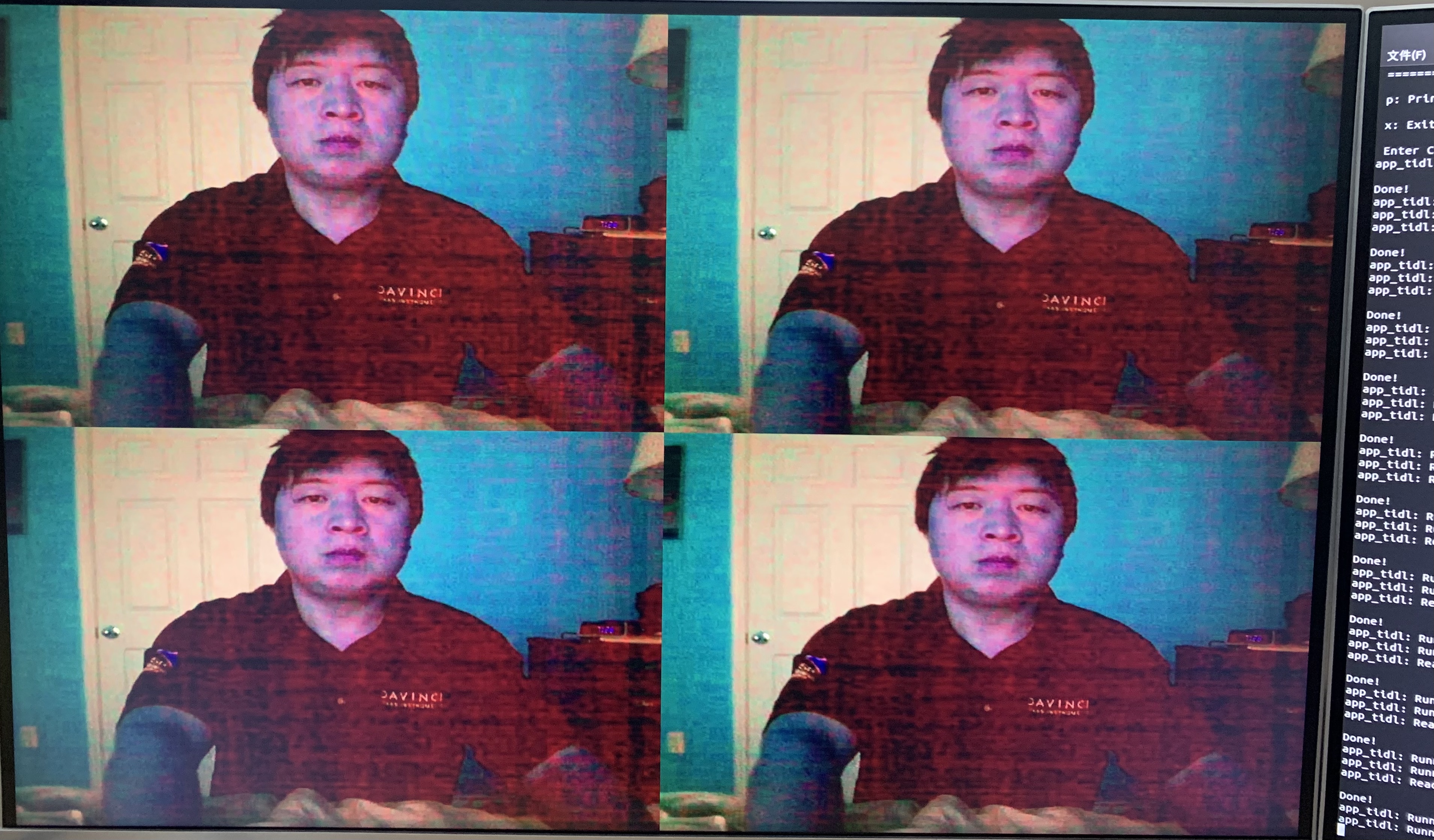
Let's see the renderings first (I only have one camera here, so I copied the YUV data from one camera and displayed it in four copies):
In order to briefly explain the functions of Mosaic node, I take the original Demo as an example. The Demo location is as follows:
ti-processor-sdk-rtos-j721e-evm-08_00_00_12/vision_apps/apps/basic_demos/app_linux_arm_opengl_mosaic/
Demo function:
The picture provided in the Demo should be an engineer of the other party. It looks good. Ha ha, pay tribute to the following authors. If there is infringement, please contact to delete it.
1. Read the bin file data from the system file
2. Created an out in RGBA format image
3. Four input s in NV12 format are created image
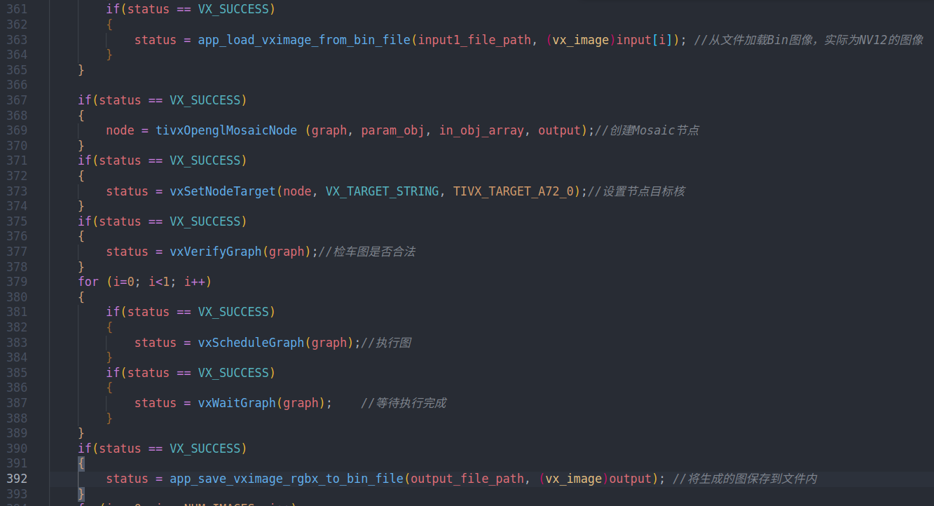
4. Load the image into the Mosaic node and execute the Graph.
The specific process is as follows:
Migration of Mosaic nodes
Based on the clues provided by the author, I transplanted this Demo to obtain YUV images from files instead of USB.
First, you need another project. I delete clean projects with only DISP nodes by myself. I will take time to download them. The link is as follows:
(temporarily unavailable, modified after uploading)
1. Migrate the concerto.mak content and add the following content to the target project.
ifeq ($(TARGET_OS),LINUX)
CFLAGS += -DEGL_NO_X11
SYS_SHARED_LIBS += gbm
endif


SYS_SHARED_LIBS += EGL
SYS_SHARED_LIBS += GLESv2

IDIRS += $(VISION_APPS_SRV_IDIRS)

STATIC_LIBS += $(VISION_APPS_SRV_LIBS)
2. Header files need to be included
#include <VX/vx.h>
#include <TI/tivx.h>
#include <TI/tivx_sample.h>
#include <tivx_sample_kernels_priv.h>
#ifdef J7
#include <app_init.h>
#endif
#include <tivx_utils_file_rd_wr.h>
#include <TI/tivx_task.h>
3. Add the following global variables for the creation and use of mosaic nodes
    vx_graph mosaicGraph;
    vx_node mosaicNode;
    vx_object_array in_obj_array;
    vx_image input[4], mosaicOutput;

    vx_user_data_object mosaicParam_obj;
    tivx_opengl_mosaic_params_t mosaicParams;
4. Initialize the global variable just created in app_init
Create four images in NV12 format, package the four NV12 to generate an array, then create an RGBX output image, and create a parameter object mosaicparam using the mosaicParams parameter_ Obj, used to create nodes.
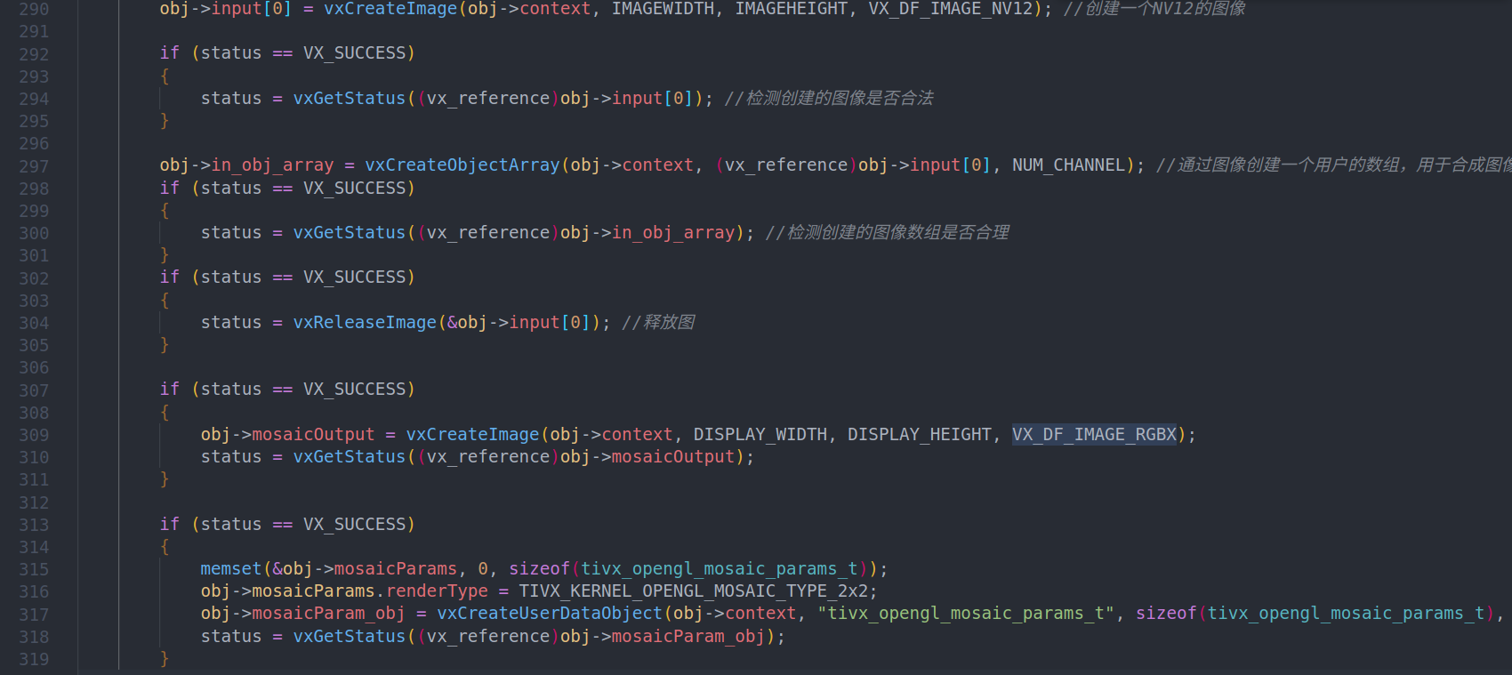
5. Create a Graph and put the code here in the app_ create_ In Graph (appobj * obj)
    //Create a few points to merge the image into an RGB image and wait for display
    if(status == VX_SUCCESS)
    {
        obj->mosaicNode = tivxOpenglMosaicNode(obj->mosaicGraph, obj->mosaicParam_obj, obj->in_obj_array, obj->mosaicOutput);
    }
    if (status == VX_SUCCESS)
    {
        status = vxSetNodeTarget(obj->mosaicNode, VX_TARGET_STRING, TIVX_TARGET_A72_0);
    }
6. verify graph in app_ verify_ In graph (appobj * obj)
    if (status == VX_SUCCESS)
    {
        status = vxVerifyGraph(obj->mosaicGraph);
    }
7. Copy the YUV data obtained by USB into 4 input s. It needs to be copied four times, so it is put in a for loop.
(the image pointer provided by USB is pmap. Here, USB obtains image data. I will write a separate blog. The link is as follows:)
(temporarily unavailable)

vxMapImagePatch vxCopyImagePatch and so on, corresponding to different images, the method is different.
8. After executing step 7, you can execute the graph and run
if (status == VX_SUCCESS)
{
if (status == VX_SUCCESS)
{
status = vxScheduleGraph(obj->mosaicGraph);
}
if (status == VX_SUCCESS)
{
status = vxWaitGraph(obj->mosaicGraph);
}
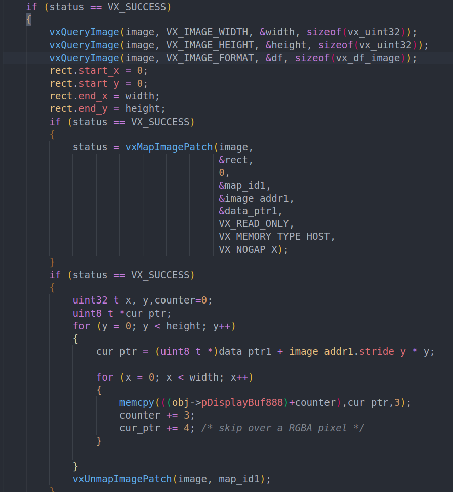
}9. After successful execution, the output image, RGBX, will be copied to disp_ Display in image.
Special note: to copy data into the image created by the kernel, you need to perform a series of operations. This will also be written in a separate blog (link is as follows:)
It should be noted that the method of converting RGBX to RGB can be implemented by yourself. I don't do conversion here for the time being. I just copy the first three bytes of RGBX and display them.
10. Execute disp_graph, you can see that after compilation, it can run normally.
I'll pack the whole project and put it in the database. It doesn't seem to fit here.
Due to limited ability, there are many places that are not clear enough. If you have questions, you are welcome to exchange private letters.