1) Experimental platform: new starting point V2 development board of punctual atom
2) Platform purchase address: https://detail.tmall.com/item.htm?id=609758951113
2) Full set of experimental source code + manual + video download address: http://www.openedv.com/thread-300792-1-1.html
3) Students interested in punctual atomic FPGA can add group discussion: 994244016
4) pay attention to the official account of the dot atom and get updated information.

Chapter 26 infrared remote control experiment
Infrared remote control is a wireless and non-contact control technology. It has the remarkable characteristics of strong anti-interference ability, reliable information transmission, low power consumption and easy implementation. It is widely used by many electronic devices, especially household appliances, and is more and more applied to computer systems. In this chapter, we will use the new starting point FPGA development board to receive the infrared signal sent by the infrared remote controller and display the data on the nixie tube. If a duplicate code is detected, it will be indicated by LED flashing.
This chapter is divided into the following chapters:
2525.1 introduction
25.2 experimental tasks
25.3 hardware design
25.4 program design
25.5 download verification
26.1 introduction
Infrared remote control is a wireless and non-contact control technology. Because it does not have the ability to control the controlled object through obstacles like radio remote control, infrared remote controllers of similar products can have the same remote control frequency or code without controlling or interfering with neighbors' household appliances, This provides great convenience for mass production and popularization of infrared remote control in household appliances. What the infrared remote controller emits is actually a kind of infrared light (infrared), whose wavelength range is between 1mm and 760nm, while the wavelength range of visible light of human eyes is generally between 400nm and 760nm, so we can't see the infrared light emitted by the infrared remote controller, so it has little impact on the environment and won't affect the adjacent radio equipment.
At present, the coding of infrared remote controller is widely used: NEC protocol and Philips RC-5 protocol. The remote controller matched with the new starting point FPGA development board uses NEC protocol, and its logic level coding format is shown in figure 26.1.1.
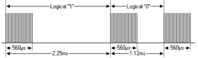
Figure 26.1.1 logic level coding format of NEC protocol
NEC protocol is encoded in the form of PPM (Pulse Position Modulation). The pulse length of each Bit of data is 560us, modulated by 38KHz carrier burst, and the recommended carrier duty cycle is 1 / 3 to 1 / 4. It can be seen from the above figure that where there are carrier pulses, the width is 560us, and the interval time of carrier pulses is different. The carrier pulse + carrier pulse interval of logic "1" is 2.25ms; The carrier pulse + carrier pulse interval of logic "0" is about half of logic "1", that is, 1.12ms.
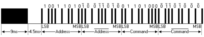
Figure 26.1.2 data transmission format of NEC protocol
Figure 26.1.2 shows the data transmission format of NEC protocol. It can be seen from the figure that the low order is the first when transmitting data. The Address code (Address) in the figure is 0x59 and the control code (Command) is 0x16. The transmission of a message starts with 9ms AGC (automatic gain control) carrier pulse, which is used to set the gain in the early IR receiver; Followed by an idle signal of 4.5ms; This is followed by the Address code and the control code. The Address code and control code are transmitted twice respectively. The Address code and control code transmitted in the second time are inverse codes, which are used to verify the Address code and control code. Of course, the inverse code of Address code and control code can also be directly ignored. Each time the information is transmitted according to the format of synchronization code (9ms carrier pulse + 4.5ms idle signal), Address code, Address inverse code, control code and control inverse code. Therefore, the time of single information transmission is fixed.
When the key on the infrared remote control is pressed all the time, the infrared remote control will only send a complete message once, and then send a repeat code (also known as continuous code) every 110ms. The data format of repetition code is relatively simple. It also starts with 9ms AGC (automatic gain control) carrier pulse, followed by 2.25ms idle signal, followed by 560us carrier pulse. The data format of repetition code is shown in Fig. 26.1.3 and Fig. 26.1.4.
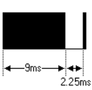
Figure 26.1.3 data format of repetition code
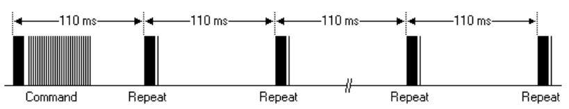
Figure 26.1.4 always sending duplicate codes
The above part is an introduction to the NEC protocol, that is, the protocol specification followed by the infrared remote controller when sending data. Next, we understand the infrared receiver on the lower development board. Its model is HS0038B. The physical diagram and structural block diagram are shown in figure 26.1.5 and figure 26.1.6.
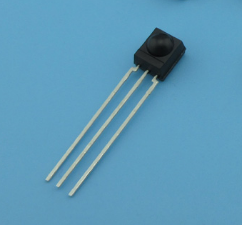
Figure 26.1.5 physical drawing of HS0038B
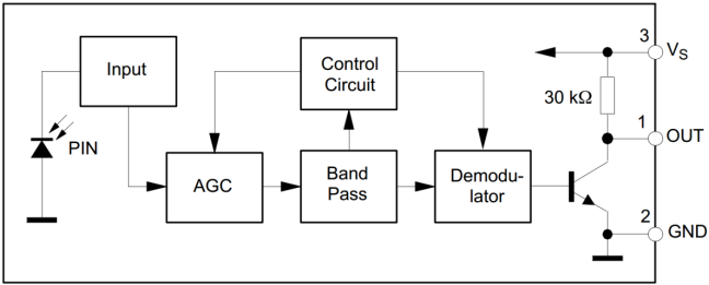
Figure 26.1.6 structural block diagram of HS0038B
The infrared receiver is usually integrated into one component by the manufacturer to become an integrated infrared receiver. Infrared monitoring diode, automatic gain amplifier (AGC), Band Pass filter (Band Pass), Demodulator and other circuits are integrated inside. The information sent by the infrared remote controller is secondary modulated by the carrier frequency of 38KHz to improve the transmission efficiency and reduce the power supply power, and then the infrared is generated by the infrared transmitting diode and transmitted into space. The infrared receiver converts the optical signal into electrical signal through the infrared monitoring diode. After circuit modulation, it finally outputs the TTL level signal that can be collected by FPGA. It should be noted here that the triode circuit inside the infrared receiving head has the function of signal reverse, that is, changing 1 to 0 and 0 to 1, then the whole protocol above will receive the level in reverse. If 9ms is originally high level, it will become low level, and so on. As shown in figure 26.1.7, the waveform corresponding to reception and decoding is the infrared signal finally received by FPGA.
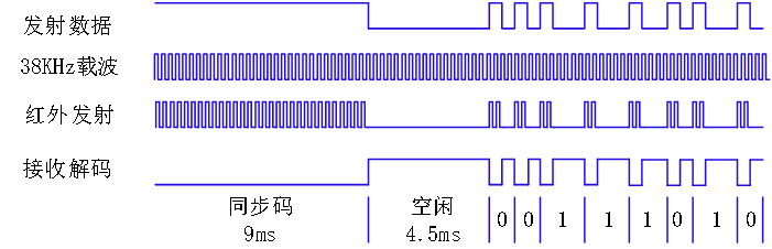
Figure 26.1.7 infrared receiving and decoding diagram
The following figure shows the complete waveform received by infrared decoding.
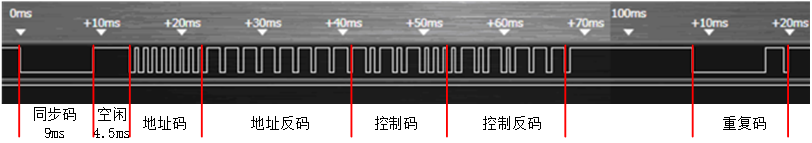
Figure 26.1.8 complete waveform received by infrared decoding
As can be seen from figure 26.1.8, the address code is 0 and the control code is 0x15. After a period of time, we can also receive several pulses, which is the repetition code (consecutive code) specified in NEC protocol. If the key is still not released after a frame of data is sent, the repetition code will be transmitted. The length / times of pressing the key can be marked by counting the repetition code.
The following figure is the key code value corresponding to the key of infrared remote control.
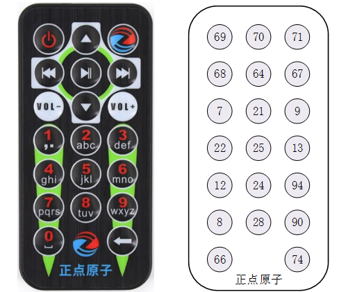
Figure 26.1.9 key code values corresponding to infrared remote control
It should be noted that the key code values on the right in the above figure are displayed in decimal numbers.
26.2 experimental tasks
The experimental task of this section is to use the new starting point FPGA development board to receive the infrared signal sent by the infrared remote controller and display the data on the nixie tube; If a duplicate code is detected, it is indicated by a flashing LED.
26.3 hardware design
The circuit schematic diagram of HS0038 is shown in figure 26.3.1, which is remote_ The in signal is the level output of the infrared receiving head.
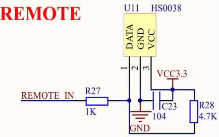
Figure 26.3.1 circuit schematic diagram of HS0038B
The pin allocation of this experiment is shown in the table below
Table 26.3.1 pin distribution of infrared remote control nixie tube display experiment
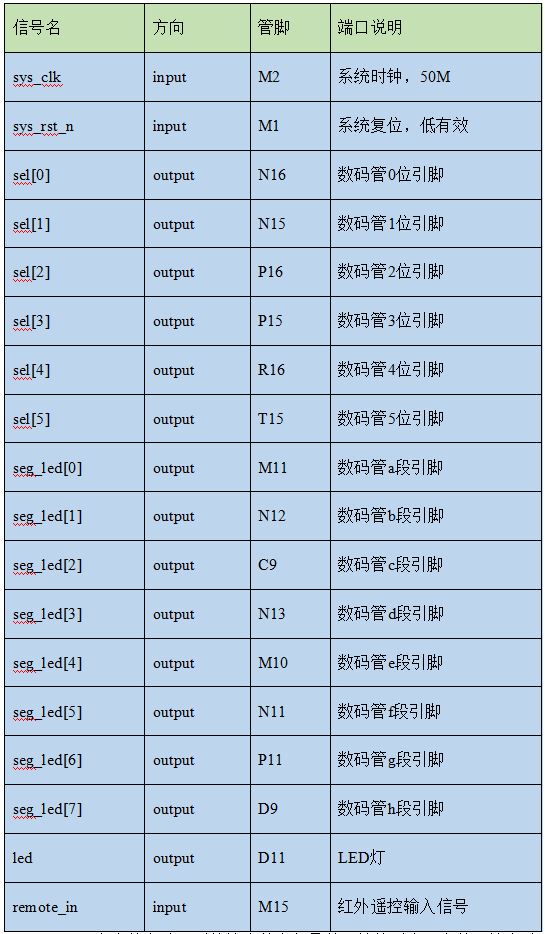
remote_in input M15 infrared remote control input signal
Because the pins used in this experiment are basically the pins of the nixie tube, which have been given in the nixie tube experiment chapter, the TCL constraint file is no longer provided here.
26.4 program design
According to the experimental task, the control process can be roughly planned. The infrared driving module analyzes the infrared data, outputs the control code to the nixie tube driving module, and the effective signal of the repeated code is output to the LED control module. The nixie tube drive module sends the corresponding bit selection and segment selection signals to the nixie tube to display the corresponding numbers on the nixie tube. The LED control module controls the lighting of the LED lamp according to the repeated code signal. The system block diagram is shown below.
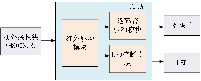
Figure 26.4.1 block diagram of infrared remote control experiment system
The schematic diagram of the top-level module is shown below
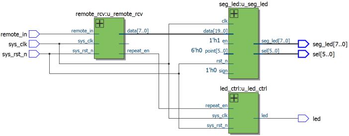
Figure 26.4.2 schematic diagram of top-level module
The FPGA top-level (top_remote_rcv) instantiates the following two modules: infrared drive module (remote_rcv) and digital tube dynamic display module (seg_led), so as to realize the signal interaction between each module.
The top-level module code is as follows:
1  module top_remote_rcv(
2      input             sys_clk  ,    //System clock
3      input             sys_rst_n,    //System reset signal, active at low level
4      input             remote_in,    //Infrared receiving signal
5      output     [5:0]  sel      ,    //Nixie tube position selection signal
6      output     [7:0]  seg_led  ,    //Nixie tube segment selection signal
7      output            led           //led lamp
8  );
9
10 //wire define
11 wire  [7:0]   data       ;
12 wire          repeat_en  ;
13
14 //*****************************************************
15 //**                    main code
16 //*****************************************************
17
18 //Nixie tube display module
19 seg_led u_seg_led(
20     .clk            (sys_clk),
21     .rst_n          (sys_rst_n),
22     .sel            (sel),
23     .seg_led        (seg_led),
24     .data           (data),           //Infrared data
25     .point          (6'd0),           //No decimal point
26     .en             (1'b1),           //Enable nixie tube
27     .sign           (1'b0)            //Unsigned display
28     );
29
30 //HS0038B drive module
31 remote_rcv u_remote_rcv(
32     .sys_clk        (sys_clk),
33     .sys_rst_n      (sys_rst_n),
34     .remote_in      (remote_in),
35     .repeat_en      (repeat_en),
36     .data_en        (),
37     .data           (data)
38     );
39
40 led_ctrl  u_led_ctrl(
41     .sys_clk       (sys_clk),
42     .sys_rst_n     (sys_rst_n),
43     .repeat_en     (repeat_en),
44     .led           (led)
45     );
46
47 endmodule
The top-level module completes the instantiation of other modules. The control code (data) output by the infrared drive module is connected to the nixie tube display module, and the output repeats_ En (repetition code valid signal) is connected to the LED control module.
From the infrared transmission timing introduced in the introduction part of this chapter, it can be found that the infrared transmission timing is very suitable for writing using state machine. The status jump diagram of infrared drive module is shown in the figure below.
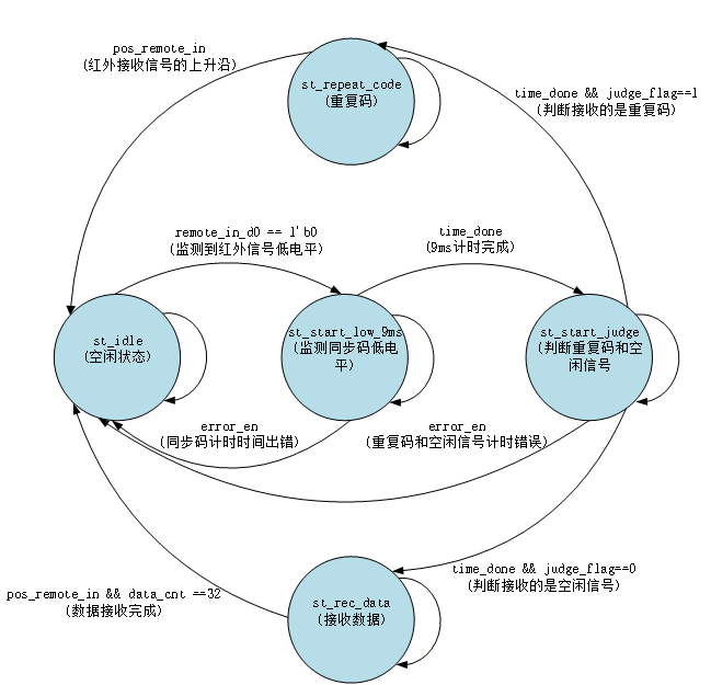
Figure 26.4.3 status jump diagram of infrared drive module
The infrared drive module uses a three-stage state machine to analyze the infrared remote control signal. From the above figure, you can intuitively see the functions realized in each state and the conditions for jumping to the next state. Since a complete infrared information and repetition code start with the synchronization code (low level of 9ms), the time of idle signal high level is different. The time of idle signal high level of a complete infrared information is 4.5ms, while the time of idle signal high level of repetition code is 2.25ms. So we're in st_start_judge the time of idle signal high level in the state. If the time is 4.5ms, jump to st_rec_data status; If the time is 2.25ms, jump to st_repeat status.
Some codes of infrared drive module are as follows:
1   module remote_rcv(
2       input                  sys_clk   ,  //System clock
3       input                  sys_rst_n ,  //System reset signal, active at low level
4
5       input                  remote_in ,  //Infrared receiving signal
6       output    reg          repeat_en ,  //Repetition code effective signal
7       output    reg          data_en   ,  //Data valid signal
8       output    reg  [7:0]   data         //Infrared control code
9       );
10
11  //parameter define
12  parameter  st_idle           = 5'b0_0001;  //Idle state
13  parameter  st_start_low_9ms  = 5'b0_0010;  //Monitoring synchronization code low level
14  parameter  st_start_judge    = 5'b0_0100;  //Judge the high level of repetition code and synchronization code (idle signal)
15  parameter  st_rec_data       = 5'b0_1000;  //receive data
16  parameter  st_repeat_code    = 5'b1_0000;  //Repeat code
17
18  //reg define
19  reg    [4:0]    cur_state      ;
20  reg    [4:0]    next_state     ;
21
22  reg    [11:0]   div_cnt        ;  //Frequency division counter
23  reg             div_clk        ;  //Frequency division clock
24  reg             remote_in_d0   ;  //Delay shooting of the input infrared signal
25  reg             remote_in_d1   ;
26  reg    [7:0]    time_cnt       ;  //Count each state of the infrared
27
28  reg             time_cnt_clr   ;  //Counter reset signal
29  reg             time_done      ;  //Timing completion signal
30  reg             error_en       ;  //Error signal
31  reg             judge_flag     ;  //Detected flag signal 0: synchronization code high level (idle signal) 1: repetition code
32  reg    [15:0]   data_temp      ;  //Temporarily store the received control code and control inverse code
33  reg    [5:0]    data_cnt       ;  //Count the received data
34
35  //wire define
36  wire            pos_remote_in  ;  //The rising edge of the input infrared signal
37  wire            neg_remote_in  ;  //Falling edge of input infrared signal
38
39  //*****************************************************
40  //**                    main code
41  //*****************************************************
42
43  assign  pos_remote_in = (~remote_in_d1) & remote_in_d0;
44  assign  neg_remote_in = remote_in_d1 & (~remote_in_d0);
45
46  //Clock frequency division, 50Mhz/(2*(3124+1))=8khz,T=0.125ms
47  always @(posedge sys_clk or negedge sys_rst_n  ) begin
48      if (!sys_rst_n) begin
49          div_cnt <= 12'd0;
50          div_clk <= 1'b0;
51      end
52      else if(div_cnt == 12'd3124) begin
53          div_cnt <= 12'd0;
54          div_clk <= ~div_clk;
55      end
56      else
57          div_cnt = div_cnt + 12'b1;
58  end
59
60  //Count each state of the infrared
61  always @(posedge div_clk or negedge sys_rst_n) begin
62      if(!sys_rst_n)
63          time_cnt <= 8'b0;
64      else if(time_cnt_clr)
65          time_cnt <= 8'b0;
66      else
67          time_cnt <= time_cnt + 8'b1;
68  end
69
70  //Remote for input_ In signal delay beat
71  always @(posedge div_clk or negedge sys_rst_n) begin
72      if(!sys_rst_n) begin
73          remote_in_d0 <= 1'b0;
74          remote_in_d1 <= 1'b0;
75      end
76      else begin
77          remote_in_d0 <= remote_in;
78          remote_in_d1 <= remote_in_d0;
79      end
80  end
81
82  //State machine
83  always @ (posedge div_clk or negedge sys_rst_n) begin
84      if(!sys_rst_n)
85          cur_state <= st_idle;
86      else
87          cur_state <= next_state ;
88  end
89
90  always @(*) begin
91      next_state = st_idle;
92      case(cur_state)
93          st_idle : begin                           //Idle state
94              if(remote_in_d0 == 1'b0)
95                  next_state = st_start_low_9ms;
96              else
97                  next_state = st_idle;
98          end
99          st_start_low_9ms : begin                  //Monitoring synchronization code low level
100             if(time_done)
101                 next_state = st_start_judge;
102             else if(error_en)
103                 next_state = st_idle;
104             else
105                 next_state = st_start_low_9ms;
106         end
107         st_start_judge : begin                    //Judge the high level of repetition code and synchronization code (idle signal)
108             if(time_done) begin
109                 if(judge_flag == 1'b0)
110                     next_state = st_rec_data;
111                 else
112                     next_state = st_repeat_code;
113             end
114             else if(error_en)
115                 next_state = st_idle;
116             else
117                 next_state = st_start_judge;
118         end
119         st_rec_data : begin                       //receive data
120             if(pos_remote_in && data_cnt == 6'd32)
121                 next_state = st_idle;
122             else
123                 next_state = st_rec_data;
124         end
125         st_repeat_code : begin                    //Repeat code
126             if(pos_remote_in)
127                 next_state = st_idle;
128             else
129                 next_state = st_repeat_code;
130         end
131         default : next_state = st_idle;
132     endcase
133 end
134
135 always @(posedge div_clk or negedge sys_rst_n ) begin
136     if (!sys_rst_n) begin
137         time_cnt_clr <= 1'b0;
138         time_done <= 1'b0;
139         error_en <= 1'b0;
140         judge_flag <= 1'b0;
141         data_en <= 1'b0;
142         data <= 8'd0;
143         repeat_en <= 1'b0;
144         data_cnt <= 6'd0;
145         data_temp <= 32'd0;
146     end
147     else begin
148         time_cnt_clr <= 1'b0;
149         time_done <= 1'b0;
150         error_en <= 1'b0;
151         repeat_en <= 1'b0;
152         data_en <= 1'b0;
153         case(cur_state)
154             st_idle           : begin
155                 time_cnt_clr <= 1'b1;
156                 if(remote_in_d0 == 1'b0)
157                     time_cnt_clr <= 1'b0;
158             end
159             st_start_low_9ms  : begin                             //9ms/0.125ms = 72
160                 if(pos_remote_in) begin
161                     time_cnt_clr <= 1'b1;
162                     if(time_cnt >= 69 && time_cnt <= 75)
163                         time_done <= 1'b1;
164                     else
165                         error_en <= 1'b1;
166                 end
167             end
168             st_start_judge : begin
169                 if(neg_remote_in) begin
170                     time_cnt_clr <= 1'b1;
171                     //Repeat code high level 2.25ms 2.25/0.125 = 18
172                     if(time_cnt >= 15 && time_cnt <= 20) begin
173                         time_done <= 1'b1;
174                         judge_flag <= 1'b1;
175                     end
176                     //Synchronization code high level 4.5ms 4.5/0.125 = 36
177                     else if(time_cnt >= 33 && time_cnt <= 38) begin
178                         time_done <= 1'b1;
179                         judge_flag <= 1'b0;
180                     end
181                     else
182                         error_en <= 1'b1;
183                 end
184             end
185             st_rec_data : begin
186                 if(pos_remote_in) begin
187                     time_cnt_clr <= 1'b1;
188                     if(data_cnt == 6'd32) begin
189                         data_en <= 1'b1;
190                         data_cnt <= 6'd0;
191                         data_temp <= 16'd0;
192                         if(data_temp[7:0] == ~data_temp[15:8])    //Check control code and control inverse code
193                             data <= data_temp[7:0];
194                     end
195                 end
196                 else if(neg_remote_in) begin
197                     time_cnt_clr <= 1'b1;
198                     data_cnt <= data_cnt + 1'b1;
199                     //Analytic control code and inverse control code
200                     if(data_cnt >= 6'd16 && data_cnt <= 6'd31) begin
201                         if(time_cnt >= 2 && time_cnt <= 6) begin  //0.56/0.125 = 4.48
202                             data_temp <= {1'b0,data_temp[15:1]};  //Logical '0'
203                         end
204                         else if(time_cnt >= 10 && time_cnt <= 15) //1.69/0.125 = 13.52
205                             data_temp <= {1'b1,data_temp[15:1]};  //Logical "1"
206                     end
207                 end
208             end
209             st_repeat_code : begin
210                 if(pos_remote_in) begin
211                     time_cnt_clr <= 1'b1;
212                     repeat_en <= 1'b1;
213                 end
214             end
215             default : ;
216         endcase
217     end
218 end
219
220 endmodule
In the always statement block at the beginning of line 47 of the code, we divide the input 50MHz clock to obtain a clock with a period of 0.125ms (8kHz), that is, the infrared signal is sampled with an 8kHz clock. The reason why the clock is divided here is that the infrared signal reception process takes a long time. If a 50MHz clock sampling is used, the internally defined counter bit width will be relatively large. Therefore, we divide the input clock. Of course, it is also possible to divide the frequency to obtain clocks of other frequencies.
The code uses a three-stage state machine to analyze the infrared signal. The state machine defaults to st_idle state, and time_cnt_ The value of CLR is 1, that is, time_cnt counter stops timing; When remote is detected_ in_ After d0 is low level, time_cnt_ The value of CLR is 0, time_ The CNT counter starts timing, and the state machine jumps to st_start_low_9ms state, here we mainly introduce how the program counts the 9ms low-level synchronization code. In line 160 of the code, when POS is detected_ remote_ In (rising edge of infrared signal) is the high level, indicating that the infrared signal is pulled high at this time, that is, the low level of synchronization code ends, and time is judged at this time_ Whether the value of CNT is close to 9ms. If it is close to 9ms, it starts to jump to st_start_judge state, otherwise jump to idle state. The detection methods for idle signals, duplicate codes and data are similar later in the program, which will not be repeated here.
Figure 26.4.4 shows the waveform captured by SignalTap, from which you can clearly see the waveform diagram of each state jump of the infrared drive module. It can be observed that the bus is at high level in the idle state. After pressing the key of the remote controller, it will send 9ms low-level synchronization code and 4.5ms high-level idle signal, and then send 00000000 address code and 11111111 address inverse code; Next, the control code of 10100010 and the control inverse code of 01011101 are sent. It should be noted that the infrared remote control first sends the low order of the data, so the control code is 8'b001000101 (8'd69), which is consistent with the data in the figure. At the end of the waveform, the duplicate code sent by the infrared remote controller is received. When the program detects the duplicate code, repeat_en sends a pulse signal.
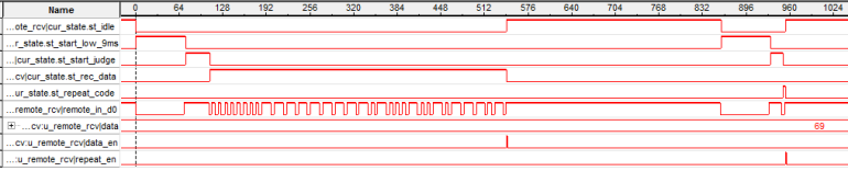
Figure 26.4.4 waveform diagram of signaltap capture
LED control module codes are as follows:
1   module led_ctrl(
2       input             sys_clk   ,  //System clock
3       input             sys_rst_n ,  //System reset signal, active at low level
4
5       input             repeat_en ,  //Repetition code trigger signal
6       output    reg     led          //LED light
7       );
8
9   //reg define
10  reg            repeat_en_d0 ;      //repeat_en signal beat acquisition edge
11  reg            repeat_en_d1 ;
12  reg    [22:0]  led_cnt      ;      //LED light counter, used to control LED light on and off
13
14  //wire define
15  wire           pos_repeat_en;
16
17  //*****************************************************
18  //**                    main code
19  //*****************************************************
20
21  assign  pos_repeat_en = ~repeat_en_d1 & repeat_en_d0;
22
23  repeat_en Signal beat edge
24  always @(posedge sys_clk or negedge sys_rst_n) begin
25      if(!sys_rst_n) begin
26          repeat_en_d0 <= 1'b0;
27          repeat_en_d1 <= 1'b0;
28      end
29      else begin
30          repeat_en_d0 <= repeat_en;
31          repeat_en_d1 <= repeat_en_d0;
32      end
33  end
34
35  always @(posedge sys_clk or negedge sys_rst_n) begin
36      if(!sys_rst_n) begin
37          led_cnt <= 23'd0;
38          led <= 1'b0;
39      end
40      else begin
41          if(pos_repeat_en) begin
42              led_cnt <= 23'd5_000_000;              //Single repetition code: on for 80ms and off for 20ms
43              led <= 1'b1;                           //led on time: 4_000_000*20ns=80ms
44          end
45          else if(led_cnt != 23'd0) begin
46              led_cnt <= led_cnt - 23'd1;
47              if(led_cnt < 23'd1_000_000)            //led off time: 1_000_000*20ns=20ms
48                  led <= 1'b0;
49          end
50      end
51  end
52
53  endmodule
The code of LED control module is relatively simple. First, check repeat_ The rising edge of the en signal (as shown by always at the beginning of line 24 of the code), POS_ repeat_ After en is pulled high, the counter is assigned to 5_ 000_ 000, and then the counter starts to decrease by 1 in each cycle until it counts to 0; At counter at 1_ 000_ 000~5_ 000_ 000, turn on the LED and turn off the LED in other cases, indicating whether the infrared remote control module detects a duplicate code.
26.5 download verification
First connect one end of the downloader to the computer and the other end to the corresponding port on the development board, then connect the power cord and turn on the power switch, and then download the sof file to the board.
After downloading, press any key on the remote control to observe the data displayed on the nixie tube; If you press and hold the key, you can observe that the LED is flashing continuously. It should be noted that before using the remote control, pull out the plastic insulating sheet at the rear of the remote control, otherwise the remote control will not work normally. The physical drawing of the remote controller is as follows:
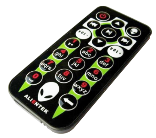
Figure 26.5.1 physical diagram of remote controller
Press the key of the remote control, and the nixie tube on the development board will display the corresponding key code value, as shown in the figure below:
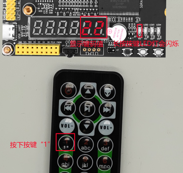
Figure 26.5.2 display key code value