4, Experimental conclusion
1. Experimental task 1
Task 1-1
- task1_1.asm source code
 1 assume ds:data, cs:code, ss:stack
 2
 3 data segment
 4     db 16 dup(0)
 5 data ends
 6
 7 stack segment
 8     db 16 dup(0)
 9 stack ends
10 code segment
11 start:
12     mov ax, data
13     mov ds, ax
14
15     mov ax, stack
16     mov ss, ax
17     mov sp, 16
18
19     mov ah, 4ch
20     int 21h
21 code ends
22 end start
- task1_1 screenshot before the end of line17 and line19
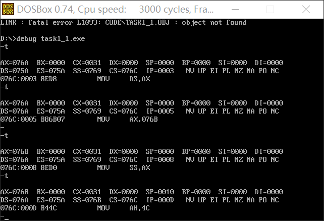
- Question answer
① In debug, execute until the end of line17 and before line19. Record this time: register (DS) = 076A, register (SS) = 076B, register (CS) =076C
② Assuming that the segment address of the code segment is X after the program is loaded, the segment address of the data segment is X-2 and the segment address of the stack is X-1.
Task 1-2
- Task task1_2.asm source code
 1 assume ds:data, cs:code, ss:stack
 2
 3 data segment
 4     db 4 dup(0)
 5 data ends
 6
 7 stack segment
 8     db 8 dup(0)
 9 stack ends
10 code segment
11 start:
12     mov ax, data
13     mov ds, ax
14
15     mov ax, stack
16     mov ss, ax
17     mov sp, 8
18
19     mov ah, 4ch
20     int 21h
21 code ends
22 end start
- task1_2. After debugging to the end of line17 and before line19, observe the screenshot of register DS, CS and SS values

- Question answer
① In debug, execute until the end of line17 and before line19. Record this time: register (DS) = 076A, register (SS) = 076B, register (CS) = 076C
② Assuming that the segment address of the code segment is X after the program is loaded, the segment address of the data segment is X-2 and the segment address of the stack is X-1.
The segment is in 16 bytes, accounting for 16 bytes, and the segment address is added by one.
Task 1-3
- Task task1_3.asm source code
 1 assume ds:data, cs:code, ss:stack
 2
 3 data segment
 4     db 20 dup(0)
 5 data ends
 6
 7 stack segment
 8     db 20 dup(0)
 9 stack ends
10 code segment
11 start:
12     mov ax, data
13     mov ds, ax
14
15     mov ax, stack
16     mov ss, ax
17     mov sp, 20
18
19     mov ah, 4ch
20     int 21h
21 code ends
22 end start
- task1_3. Screenshot of the values of registers DS, CS and SS before the end of debugging to line17 and line19

- Question answer
① In debug, execute until the end of line17 and before line19. Record this time: register (DS) = 076A, register (SS) = 076C, register (CS) = 076E
② Assuming that the segment address of the code segment is X after the program is loaded, the segment address of the data segment is X-4 and the segment address of the stack is X-2.
Tasks 1-4
- Task task1_4.asm source code
 1 assume ds:data, cs:code, ss:stack
 2 code segment
 3 start:
 4     mov ax, data
 5     mov ds, ax
 6
 7     mov ax, stack
 8     mov ss, ax
 9     mov sp, 20
10
11     mov ah, 4ch
12     int 21h
13 code ends
14
15 data segment
16     db 20 dup(0)
17 data ends
18
19 stack segment
20     db 20 dup(0)
21 stack ends
22 end start
- task1_4. After debugging to the end of line17 and before line19, observe the screenshot of register DS, CS and SS values
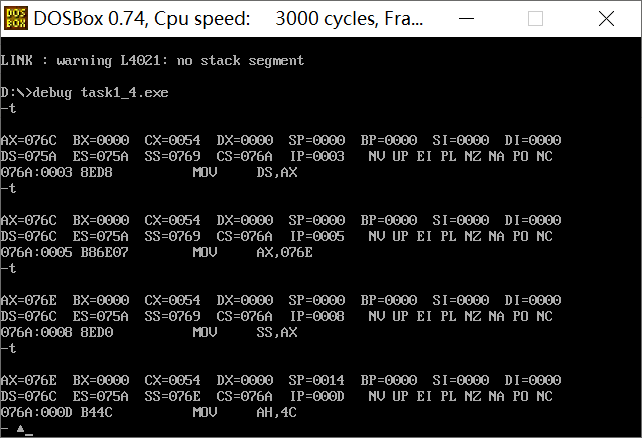
- Question answer
① In debug, execute until the end of line9 and before line11. Record this time: register (DS) = 076C, register (SS) = 076E, register (CS) = 076A.
② Assuming that the segment address of the code segment is X after the program is loaded, the segment address of the data segment is X+2 and the segment address of the stack is X+4.
The code segment occupies 16 bytes first.
Tasks 1-5
Based on the practice and observation of the above four experimental tasks, summarize and answer:
① For the segment defined below, after the program is loaded, the actual memory space allocated to the segment is (N+15) / 16.
1 xxx segment
2     db N dup(0)
3 xxx ends
② If the program Task1_ 1.asm, task1_ 2.asm, task1_ 3.asm, task1_ 4. In ASM, if the pseudo instruction end start is changed to end, which program can still be executed correctly. The reasons are analyzed and explained in combination with the conclusions obtained from practical observation.
task1_1,task1_2,task1_3 cannot execute correctly, task1_4 can be executed correctly.
When the assembler processes the assembly source program, it will first process the pseudo instructions. The start pseudo instruction indicates that the code segment starts from here and will be sent to the CS segment register. Since start and end start need to appear in pairs, after the assembler finds start, it does not find end start, and start fails, so the program is executed from the beginning by default. CS and IP point to the beginning of the program. The beginning of 1,2,3 is not a code segment, and 4 is, so it can be executed correctly.
2. Experimental task 2
- Assembly source code
 1 assume cs:code
 2 code segment
 3 start:
 4     mov ax,0b800h
 5     mov ds,ax
 6     mov bx,0f00h
 7     mov cx,80
 8 p:
 9     mov ds:[bx],0403h
10     inc bx
11     inc bx
12     loop p
13
14     mov ah,4ch
15     int 21h
16 code ends
17 end start
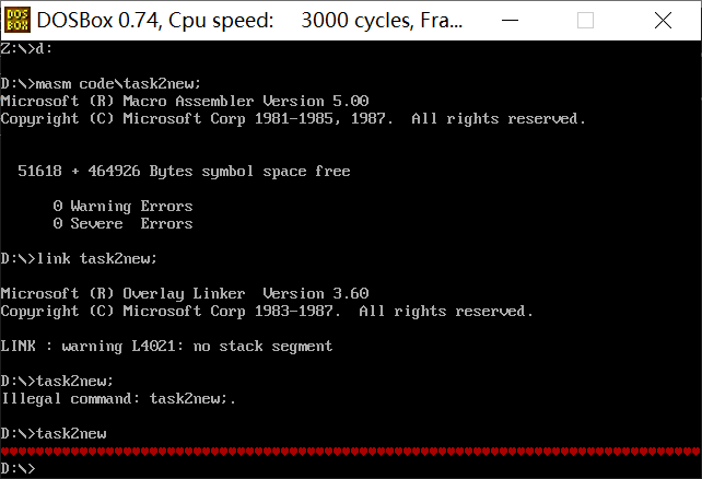
- Screenshot of operation results
3. Experimental task 3
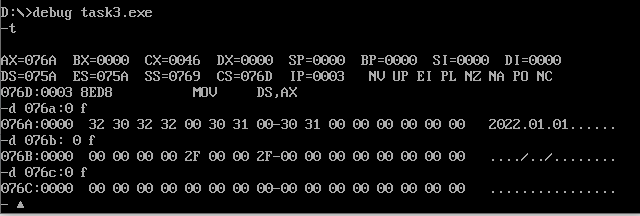
- Complete assembly source code
-
 1 assume cs:code
 2 data1 segment
 3     db 50, 48, 50, 50, 0, 48, 49, 0, 48, 49 ; ten numbers
 4 data1 ends
 5
 6 data2 segment
 7     db 0, 0, 0, 0, 47, 0, 0, 47, 0, 0       ; ten numbers
 8 data2 ends
 9
10 data3 segment
11     db 16 dup(0)
12 data3 ends
13
14 code segment
15 start:
16     mov ax,data1
17     mov ds,ax
18     mov cx,16
19     mov bx,0
20 s:  mov al,ds:[bx]
21     add al,ds:[bx+16]
22     mov ds:[bx+32],al
23     inc bx
24     loop s

25     mov ah,4ch
26     int 21h
27 code ends
28 end start
- Load, disassemble and debug screenshots in debug
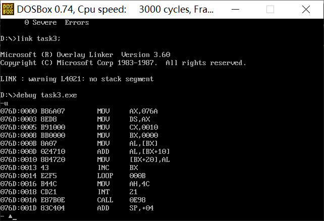
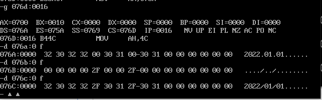
It is required to give the debug command and screenshot to view the original value of memory space data corresponding to logical segments data1, data2 and data3 before adding data items in turn
And, after adding in turn, view the debug command and screenshot of the original value of memory space data corresponding to logical segments data1, data2 and data3
4. Experimental task 4
- Complete assembly source code
 1 assume cs:code
 2
 3 data1 segment
 4     dw 2, 0, 4, 9, 2, 0, 1, 9
 5 data1 ends
 6
 7 data2 segment
 8     dw 8 dup(?)
 9 data2 ends
10
11 code segment
12 start:
13     mov ax, data1
14     mov ds, ax
15     mov ax, data2
16     mov ss, ax
17     mov sp, 16
18     mov bx, 0
19     mov cx, 8
20   s:push [bx]
21     add bx, 2
22     loop s
23
24     mov ah, 4ch
25     int 21h
26 code ends
27 end start
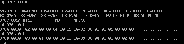
- Load, disassemble and debug screenshots in debug
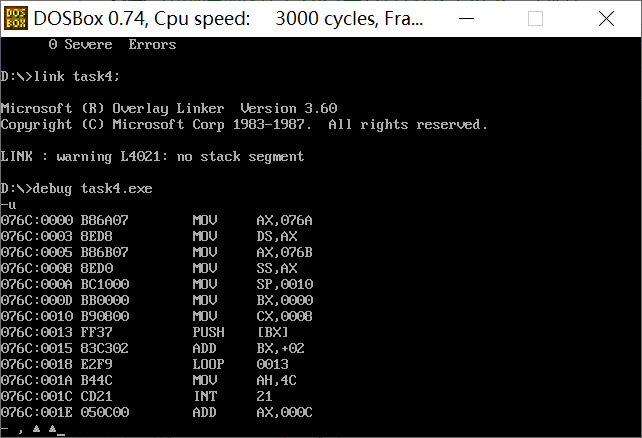
It is required to give a screenshot of the memory space corresponding to data segment data2 by using the d command before the program exits.
5. Experimental task 5
- task5.asm source code
 1 assume cs:code, ds:data
 2 data segment
 3         db 'Nuist'
 4         db 2, 3, 4, 5, 6
 5 data ends
 6
 7 code segment
 8 start:
 9         mov ax, data
10         mov ds, ax
11
12         mov ax, 0b800H
13         mov es, ax
14
15         mov cx, 5
16         mov si, 0
17         mov di, 0f00h
18 s:      mov al, [si]
19         and al, 0dfh
20         mov es:[di], al
21         mov al, [5+si]
22         mov es:[di+1], al
23         inc si
24         add di, 2
25         loop s
26
27         mov ah, 4ch
28         int 21h
29 code ends
30 end start
- Screenshot of operation results
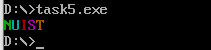
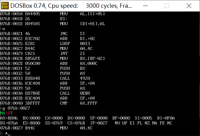
- Use the debug tool to debug the program, and use the g command to execute the screenshot before the program returns (i.e. after ine25 and before line27)
- What is the function of line19 in the source code?
0dfh is binary 1101 1111. Perform and operation, change the sixth bit of al to 0, and convert lowercase to uppercase.
- What is the purpose of the byte data in the data segment line4 in the source code?
Modify the line4 value and find that the purpose is to change the letter color.
6. Experimental task 6
- task6.asm source code
 1 assume cs:code, ds:data
 2
 3 data segment
 4     db 'Pink Floyd      '
 5     db 'JOAN Baez       '
 6     db 'NEIL Young      '
 7     db 'Joan Lennon     '
 8 data ends
 9
10 code segment
11 start:
12    mov ax,data
13    mov ds,ax
14    mov cx,4
15    mov bx,0
16 s1:
17    mov dx,cx
18    mov cx,4
19    mov si,0
20       s2:
21          mov al,ds:[bx+si]
22          or al,020h
23          mov ds:[bx+si],al
24          inc si
25          loop s2
26    add bx,16
27    mov cx,dx
28    loop s1
29    mov ah, 4ch
30    int 21h
31 code ends
32 end start
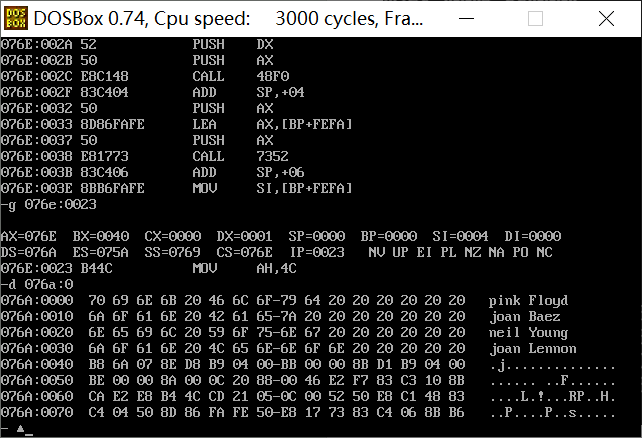
- Load, disassemble and debug screenshots in debug
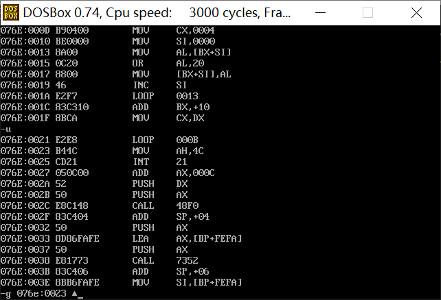
It is required to give a screenshot of the memory space corresponding to the data segment data by using the d command before the program exits.
7. Experimental task 7
- task7.asm source code
 1 assume cs:code, ds:data, es:table
 2
 3 data segment
 4     db '1975', '1976', '1977', '1978', '1979'
 5     dw  16, 22, 382, 1356, 2390
 6     dw  3, 7, 9, 13, 28
 7 data ends
 8
 9 table segment
10     db 5 dup( 16 dup(' ') )  ;
11 table ends
12
13 code segment
14 start:
15     mov ax,data
16     mov ds,ax
17     mov ax,table
18     mov es,ax
19
20     mov bx,0
21     mov bp,0
22     mov si,20
23     mov cx,5
24
25 s:  mov ax,ds:[bx]
26     mov es:[bp],ax
27     mov ax,ds:[bx+2]
28     mov es:[bp+2],ax
29
30     mov ax,ds:[si]
31     mov es:[bp+5],ax
32     mov word ptr es:[bp+7],0
33
34     mov ax,ds:[si+10]
35     mov es:[bp+10],ax
36
37     mov ax,ds:[si]
38     mov dl,ds:[si+10]
39     div dl
40     mov es:[bp+13],al
41     mov byte ptr es:[bp+14],0
42
43     add bx,4
44     add bp,16
45     add si,2
46
47     loop s
48
49     mov ah, 4ch
50     int 21h
51 code ends
52 end start
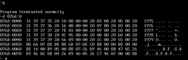
- Debug screenshot
View screenshot of original data information of table segment
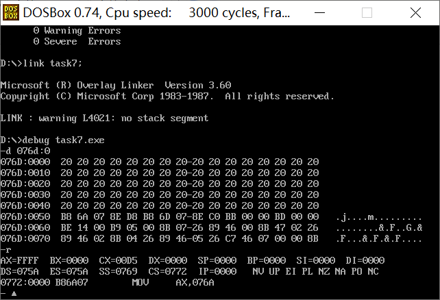
Run in debug until the program exits, use the d command to view the screenshot of the memory space corresponding to the table segment, and confirm whether the information is structurally written to the specified memory as required
5, Experimental summary
1.start: As a label of the assembler, it defines the entry of the program, that is, the program starts to execute from start:. If the first instruction of the program is the entry of the program, start can be defaulted.
start The structure used is as follows:
start: \ Define the entry of the program
...
end start \ Define end of segment
among strat It can be replaced by other characters, but the corresponding end strat Strat in It must also be replaced by the same character.
If the first strat defaults, end In strat strat It must also be removed.
2. Add instruction (addition), format: add a, B / / a = a + B;, Function: add two numbers.
3. Store in reverse order and use stack.