1, I2C bus communication protocol
1.I2C protocol
I2C (inter integrated circuit), an integrated circuit bus, is a serial communication bus. It uses a multi master-slave architecture. It was designed by Philips in the early 1980s to facilitate the communication between the motherboard, embedded system or mobile phone and peripheral equipment components. Because of its simplicity, it is widely used in the communication between microcontroller and sensor array, display, IoT device, EEPROM, etc.
2.I2C physical layer
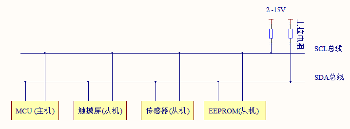
I2C bus consists of SDA (serial data line), SCL (serial clock line) and pull-up resistor respectively. By controlling the high and low level timing of SCL and SDA lines, the signals required by I2C bus protocol are generated for data transmission. When the bus is idle, the two wires are generally pulled high by the pull-up resistance connected above to maintain a high level.
Common I2C communication system
2.I2C protocol layer
Each device on the I2C bus can be used as a master or slave device, and each device will correspond to a unique device address. Usually, we use the CPU module as the master device and other devices connected to the bus as the slave device. Bidirectional data transmission is carried out between master equipment and slave equipment on I2C bus in units of 8 bytes, and each unit must be followed by an ACK bit. The data is placed on the SDA data line when SCL is at low level, and the data is sampled when SCL is at high level.
I2C bus data transmission protocol sequence diagram
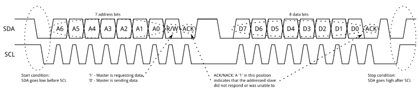
As can be seen from the figure, the transmission sequence of I2C bus includes: start condition, address frame, data frame, stop condition and repeat start condition.
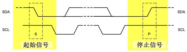
Start condition and stop condition: when SCL line is at high level, SDA line switches from high level to low level, which indicates the beginning of communication. When SCL is high, SDA line switches from low level to high level, indicating the stop of communication. Start and stop conditions are generally generated by the host.
Start and stop signals
Address frame: the address frame always appears at the beginning of a communication, usually including a 7-bit device address (MSB) and the last 1-bit read-write control bit (1 indicates read and 0 indicates write), followed by a 1-bit NACK/ACK. When the 8-bit address is sent, the Slave device obtains the control of the SDA. At this time, the Slave device should reply to an ACK (pull the SDA down) before the 9th clock pulse To indicate that the data reception is normal, otherwise it indicates that the data acceptance fails, and the control right is handed over to the Master device for processing.
Data frame: each data frame has 8 bits, and the number of data frames can be arbitrary until the stop condition is generated. After each 8-bit data transmission is completed, the receiver needs to reply to an ACK/NACK.
Repeat start condition: sometimes the Master device needs to exchange messages multiple times in one communication (such as switching read-write operations, etc.) and does not want interference from other Master devices. At this time, the repeat start condition can be used, and finally a stop condition can be generated to end the whole communication process.
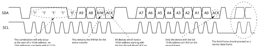
I2C also supports 10 bit address space. For the transmission timing of 10 bit address, two address frames are required to complete the address transmission. Other transmission protocols are the same as those of 8-bit.
10 bit address transmission sequence diagram
The resistance value of the pull-up resistance of I2C bus should be carefully considered. If the resistance value of the pull-up resistance is too large, the rising edge and falling edge of the signal will slow down due to the existence of the input capacitance at the input end of I2C equipment, so that it can not meet the establishment time and holding time of I2C equipment, resulting in communication errors; If the pull-up resistance is too small, it will cause large power loss. Therefore, the resistance value of the pull-up resistance of I2C communication should meet the requirements of the rising and falling edges of the equipment, and try to select a larger resistance value to reduce the power consumption.
3. Software I2C and hardware I2C
Software I2C: according to the timing requirements of the signal, use the software to directly control the status of the two GPIO pins of STM32 (used as SCL and SDA pins respectively) to simulate I2C communication. When directly controlling the GPIO pin level to generate communication timing, the CPU needs to control the pin state at each time, which is called software I2C.
Hardware IIC: the I2C on-chip peripheral of STM32 is specially responsible for implementing the I2C communication protocol and directly calling the internal register for configuration. It will automatically generate communication signals according to the protocol requirements, send and receive data and cache it. As long as the CPU detects the status of the peripheral and accesses the data register, it can complete data sending and receiving.
Hardware I2C reduces the work of CPU, and its efficiency is much higher than that of software, while software I2C has flexible interface because it is not limited by pins.
2, Data acquisition based on STM32 and AHT20 temperature and humidity sensor
1. Tasks
The temperature and humidity data are collected every 2 seconds, and the collected temperature and humidity values are connected and sent to the upper computer (win10) through the serial port.
2. Main code
Directly read the temperature and humidity data of AHT20
void AHT20_Read_CTdata(u32 *ct)
{
	volatile u8 Byte_1th=0,Byte_2th=0,Byte_3th=0;
    volatile u8 Byte_4th=0,Byte_5th=0,Byte_6th=0;
	u32 RetuData = 0;
	u16 cnt = 0,flag;
	AHT20_SendAC();//Send AC command to AHT20
	delay_ms(80);//About 80ms delay

	while(((AHT20_Read_Status()&0x80)==0x80))//Until the status bit[7] is 0, it indicates an idle state,
	{
		delay_ms(1);
		if(cnt++>=100) break;
	}

	IIC_Start();
	IIC_Send_Byte(0x71);
	flag=IIC_Wait_Ack();
	Byte_1th = IIC_Read_Byte(flag);//Status word
	Byte_2th = IIC_Read_Byte(flag);//Humidity, send ACK (continue sending)
	Byte_3th = IIC_Read_Byte(flag);//humidity
	Byte_4th = IIC_Read_Byte(flag);//Humidity / temperature
	Byte_5th = IIC_Read_Byte(flag);//temperature
	Byte_6th = IIC_Read_Byte(!flag);//Temperature, send NAK (stop sending)
	IIC_Stop();

    //Save the obtained data to RetuData
	RetuData = (RetuData|Byte_2th)<<8;
	RetuData = (RetuData|Byte_3th)<<8;
	RetuData = (RetuData|Byte_4th);
	RetuData =RetuData >>4;
	ct[0] = RetuData;//humidity

	RetuData = 0;
	RetuData = (RetuData|Byte_4th)<<8;
	RetuData = (RetuData|Byte_5th)<<8;
	RetuData = (RetuData|Byte_6th);
	RetuData = RetuData&0x0fffff;
	ct[1] =RetuData; //temperature
}
Main function
#include "led.h"
#include "delay.h"
#include "temhum.h"
#include "sys.h"
#include "usart.h"

 int main(void)
 {
    u32 CT_data[2]={0};
    volatile float  hum=0,tem=0;

    delay_init();//Delay function initialization
    NVIC_PriorityGroupConfig(NVIC_PriorityGroup_2);//Set NVIC interrupt packet 2: 2-bit preemption priority and 2-bit response priority
    uart_init(115200);//The serial port is initialized to 115200
    LED_Init(); //LED port initialization
    temphum_init();//ATH20 initialization

	while(1)
	{
        AHT20_Read_CTdata(CT_data);//Directly read the temperature and humidity data of AHT20 without CRC verification

        hum = CT_data[0]*100*10/1024/1024;//Calculated humidity value (magnified by 10 times)
        tem = CT_data[1]*200*10/1024/1024-500;//Calculated temperature value (magnified by 10 times)

        printf("humidity:%.1f%%\r\n",(hum/10));
        printf("temperature:%.1f degree\r\n",(tem/10));
        printf("\r\n");

        //With a delay of 2S, the LED flashes to prompt the serial port sending status
        LED=0;
        delay_ms(1000);
        LED=1;
        delay_ms(1000);
	 }
}
You can refer to the official Manual of AHT20 and the complete code of the project for further study, and the link is put in the reference materials.
3. Pin connection
AHT20
| AHT20 | STM32 |
|---|---|
| SCL | PB6 |
| SDA | PB7 |
| VCC | 3V3 |
| GND | GND |
Serial port
| STM32 | USB to TTL |
|---|---|
| PA9 | TXD |
| PA10 | RXD |
| 3V3 | 3V3 |
| GND | GND |
4. Operation effect
It can be seen that the temperature and humidity data are collected every 2 seconds and output through the serial port. After touching the AHT20 chip, the temperature and humidity values change significantly.
3, Summary
After completing this experiment on the basis of understanding the I2C protocol, I suddenly feel that the household appliances around me are not difficult to understand. I2C, as a serial communication bus, solves the communication problem between devices. I2C bus is a simple bidirectional binary synchronous serial bus. It only needs two bidirectional I/O lines to realize the information transmission between devices connected to the bus.
4, References
stm32 realizes the acquisition of temperature and humidity (AHT20) through I2C interface
Full code link
Extraction code: 03zq
Aosong AHT20 sensor manufacturer information
Extraction code: 95dx