Experiment 3 Transfer Instruction Jump Principle and Simple Application Programming
1. Experimental Purpose
-
Understanding and mastering the jump principle of transfer instructions
-
Learn how to implement subroutines using call and ret instructions, understand and understand how their parameters are passed
-
Understanding and mastering 80 × 25 Color Character Mode Display Principle
-
Complete simple application programming by synthesizing addressing methods and assembly instructions
2. Preparing for Experiment
Review textbook chapters 9-10:
-
Jump principle of transfer instructions
-
Usage of assembly instructions jmp, loop, jcxz, call, ret, retf
3. Experimental Contents
1. Experimental Task 1
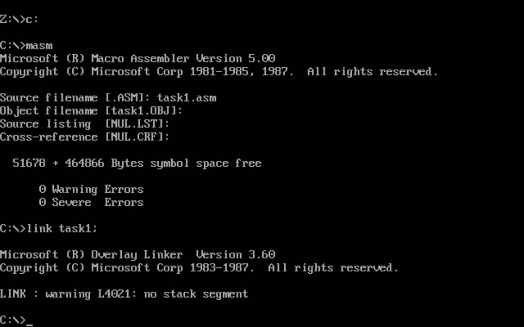
Using any text editor, enter the 8086 assembler source task1.asm.
 1 assume cs:code, ds:data
 2
 3 data segment
 4     x db 1, 9, 3
 5     len1 equ $ - x
 6
 7     y dw 1, 9, 3
 8     len2 equ $ - y
 9 data ends
10
11 code segment
12 start:
13     mov ax, data
14     mov ds, ax
15
16     mov si, offset x
17     mov cx, len1
18     mov ah, 2
19  s1:mov dl, [si]
20     or dl, 30h
21     int 21h
22
23     mov dl, ' '
24     int 21h
25
26     inc si
27     loop s1
28
29     mov ah, 2
30     mov dl, 0ah
31     int 21h
32
33     mov si, offset y
34     mov cx, len2/2
35     mov ah, 2
36  s2:mov dx, [si]
37     or dl, 30h
38     int 21h
39
40     mov dl, ' '
41     int 21h
42
43     add si, 2
44     loop s2
45
46     mov ah, 4ch
47     int 21h
48 code ends
49 end start
Test Run:
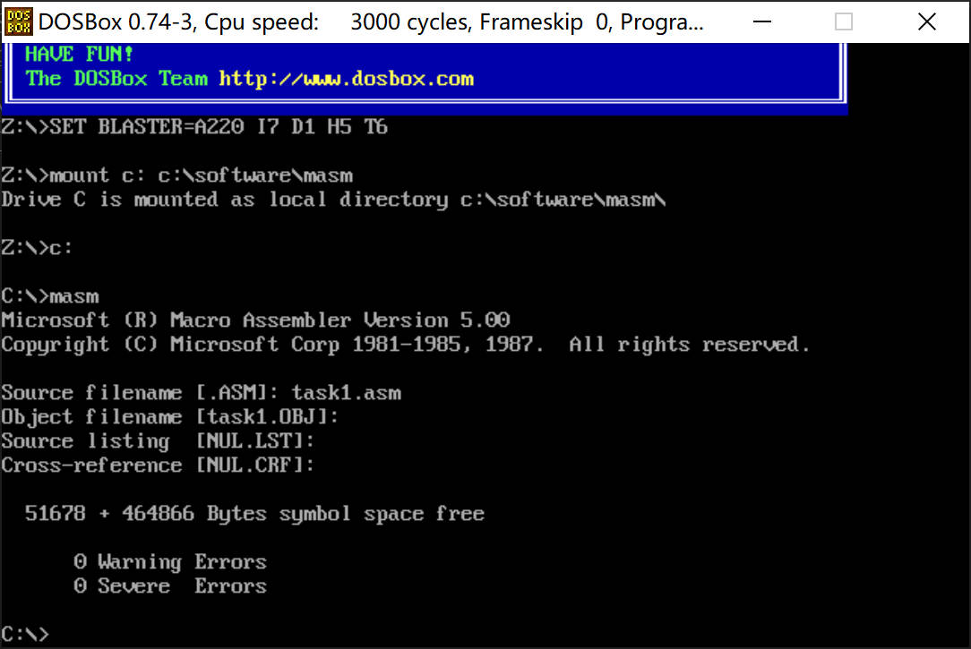
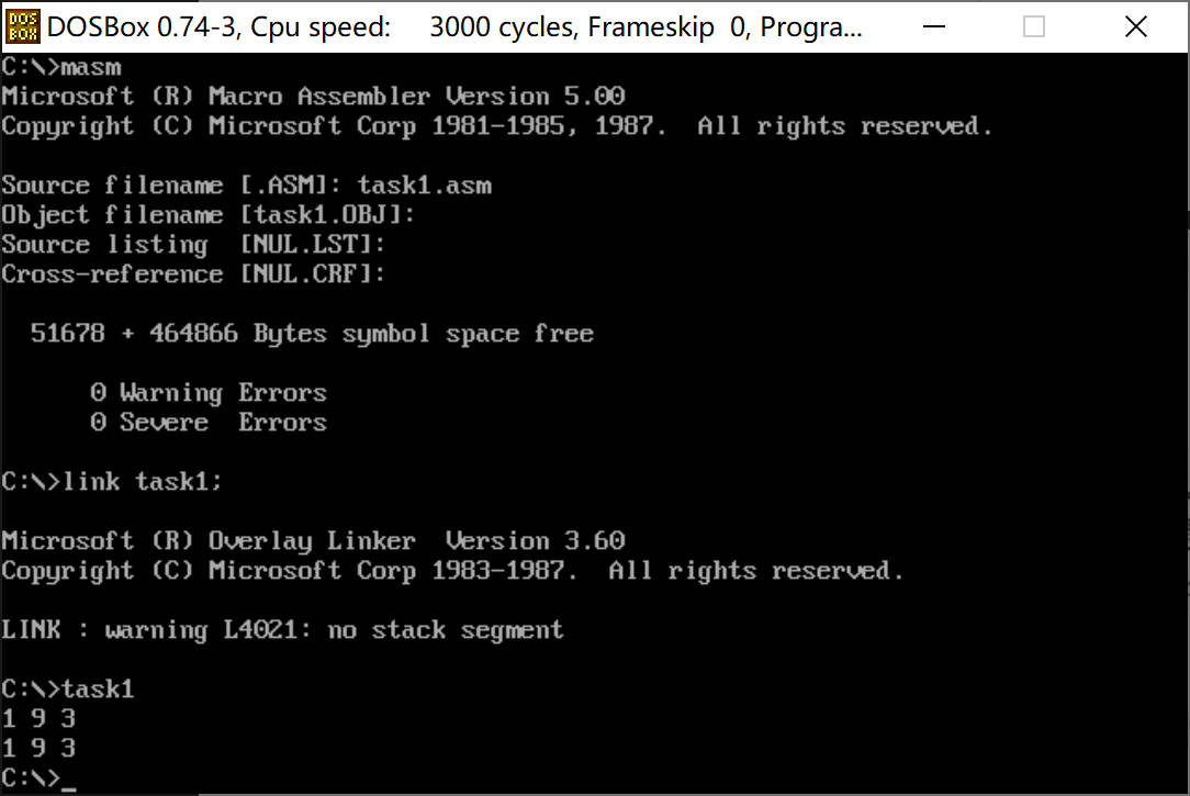
Display results output 2 lines "19 3"
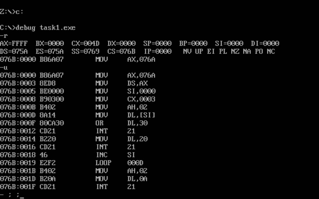
debug view:
Question answering
(1) line27, assembly instructions loop s1 When jumping, it jumps according to the amount of displacement. Through debug disassembly, look at its machine code, analyze its jump displacement from the CPU's point of view, F2 is complement 11110010, the original code 10001110, in decimal value (-14), the estimated starting address is 27 + (-14) = 13 -> 000D (hexadecimal)
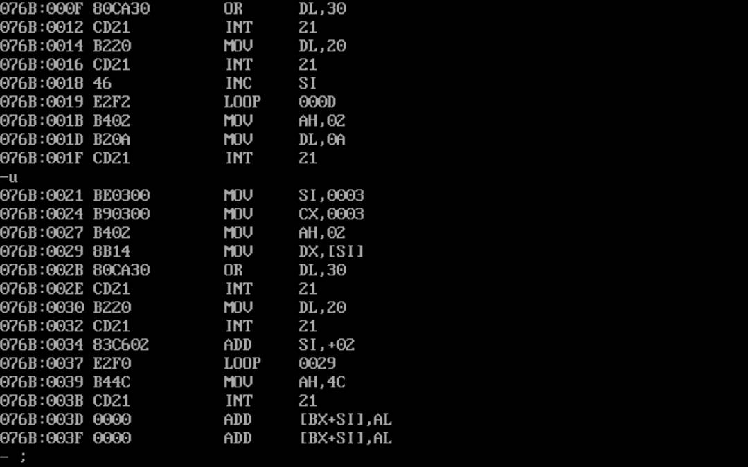
(2) line44, assembly instructions loop s2 When jumping, it jumps according to the amount of displacement. Through debug disassembly, look at its machine code, from the perspective of CPU, analyze its jump displacement, F0 is complement 11110000, original code 10010000, in decimal value (16), the estimated starting address is 57 - 16 = 41 -> 29 (hexadecimal)
2. Experimental Task 2
Using any text editor, enter the 8086 assembler source task2.asm.
 1 assume cs:code, ds:data
 2
 3 data segment
 4     dw 200h, 0h, 230h, 0h
 5 data ends
 6
 7 stack segment
 8     db 16 dup(0)
 9 stack ends
10
11 code segment
12 start:
13     mov ax, data
14     mov ds, ax
15
16     mov word ptr ds:[0], offset s1
17     mov word ptr ds:[2], offset s2
18     mov ds:[4], cs
19
20     mov ax, stack
21     mov ss, ax
22     mov sp, 16
23
24     call word ptr ds:[0]
25 s1: pop ax
26
27     call dword ptr ds:[2]
28 s2: pop bx
29     pop cx
30
31     mov ah, 4ch
32     int 21h
33 code ends
34 end start
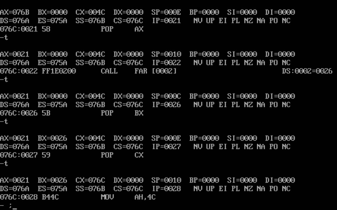
(1) According to the jump principle of call instruction, theoretical analysis is made first. Before program execution reaches line31, register (ax) = IP; register (bx) = IP; register (cx) = CS.
(2) Assemble and link the source program to get the executable program task2.exe. Use debug debugging to observe and verify the debugging results: the intra-segment offset address part of the address where the s1 code segment is stored in ax - 0021, the intra-segment offset address part of the address where the s2 code segment is stored in bx - 0026, and the intra-segment address part of the address where the s2 code segment is stored in cx - 076C.
3. Experimental Task 3
Write the 8086 assembly source program task3.asm to output this continuous set of data in decimal form on the screen, with a space interval between the data and the data. Requirements: Write two subprograms, printNumber and printSpace, to output two digits and spaces, respectively.
In the main code, a combination of addressing methods and loops is applied, calling printNumber and printSpace to achieve the title requirements. Known logical segments are defined as follows:
1 data segment
2       x db 99, 72, 85, 63, 89, 97, 55
3       len equ $- x
4 data ends
Design code, ideas are commented in the code:
 1 assume cs:code, ds:data
 2
 3 data segment
 4     x db 99, 72, 85, 63, 89, 97, 55
 5     len equ $- x
 6 data ends
 7
 8 code segment
 9 start:
10     mov ax, data
11     mov ds, ax
12
13     mov cx,len
14     mov si,0
15 s1:  mov ah,0
16     mov al,[si]
17     mov bx,offset printnumber
18     call bx
19     mov bx,offset printSpace
20     call bx
21     inc si
22     loop s1
23
24     mov ah, 4ch
25      int 21h
26
27 printnumber:
28     mov bl,10 ;Calculate Bit Ten in Decimal
29     div bl
30
31     mov bx,ax
32     mov ah,2
33
34     mov dl,bl ;Print 10 digits
35     or dl,30h ;To ASCII value
36     int 21h
37
38     mov dl,bh ;Print digits
39     or dl,30h ;To ASCII value
40     int 21h
41
42     ret
43 printSpace:
44     mov ah,2
45     mov dl,' ' ;Move into Space Print Output
46     int 21h
47     ret
48 code ends
49 end start
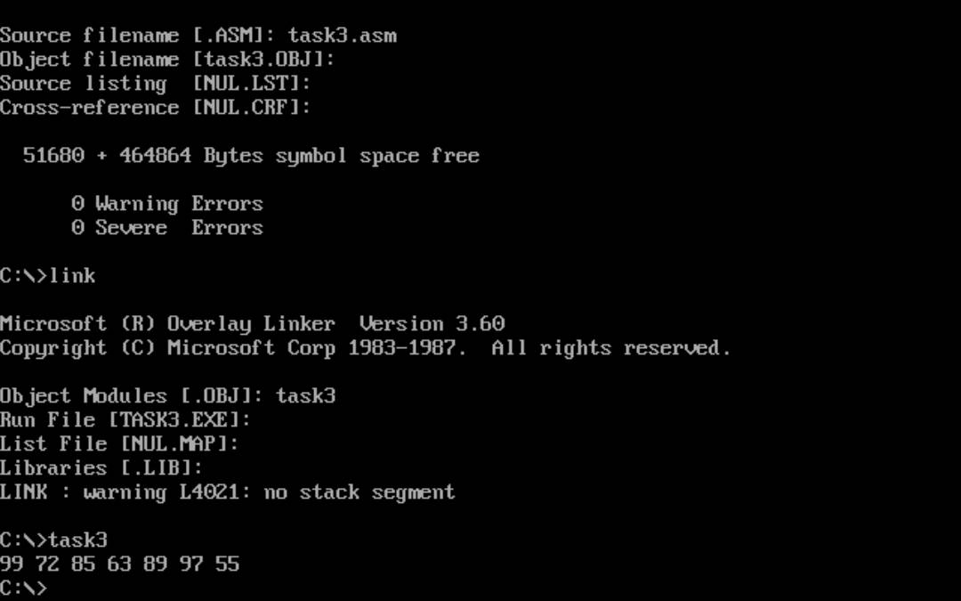
Test result: correctly output the space interval number, nice
4. Experimental Task 4
Write 8086 assembly source program task4.asm, on the screen to specify the color, the specified line, on the screen output string.
Requires the writing of a subprogram, printStr, to achieve the following functions: to specify rows, to specify colors, to display strings on the screen; In the main code, printStr is called twice so that the string is displayed in green on black at the top of the screen and red on black at the bottom.
Known logical segments are defined as follows:
1 data segment
2       str db 'try'
3       len equ $ - str
4 data ends
Design code: Ideas are commented in the code:
 1 assume cs:code, ds:data
 2
 3 data segment
 4     str db 'try'
 5     len equ $ - str
 6 data ends
 7
 8 code segment
 9 start:
10      mov ax, data
11      mov ds, ax
12     mov ax,0B800H ;Display Cache Address Start Location
13     mov es,ax
14
15     mov si,offset printTry ;First try
16     mov ah,00000010B ;Green on black is 00000010 B
17     mov bx,0 ;Position the first line
18     call si
19
20     mov si,offset printTry ;The second try
21     mov ah,00000100B ;Red on black is 00000100 B
22     mov bx,0F00H ;Position the last line
23     call si
24
25     mov ah, 4ch
26      int 21h
27
28 printTry:
29     mov cx,len
30     mov si,0
31 s1:  mov al,[si]
32     mov es:[bx+si],ax
33     inc si
34     inc bx
35     loop s1
36     ret
37
38 code ends
39 end start
Test results:
Green on black is here:
↓

↑
Red on Black Here
5. Experimental Task 5
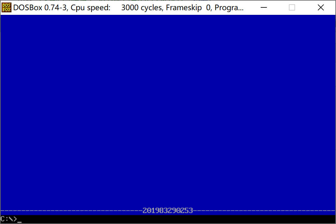
In 80x25 color character mode, the school number is displayed in the middle of the last line of the screen. The output window is required to have a blue bottom with the school number and polylines on both sides displayed in white foreground color.
Known logical segments are defined as follows:
1 data segment
2       stu_no db '201983290253' ;Own number
3       len = $ - stu_no
4 data ends
The design code is as follows:
 1 assume cs:code, ds:data
 2
 3 data segment
 4     stu_no db '201983290253'
 5     len = $ - stu_no
 6 data ends
 7
 8 code segment
 9 start:
10      mov ax, data
11      mov ds, ax  ; Data from ds Coming Middle
12     mov ax,0B800H ;Display Cache Address Start Location
13     mov es,ax    ;Data to es In, es Register Points to Display Segment
14
15     mov cx,0780H  ;Dye blue
16     mov ah,10H
17     mov al,' '
18     mov bx,0
19 s1:  mov es:[bx],ax
20     add bx,2
21     loop s1
22
23     mov cx,80;Print horizontal lines
24     mov ah,17H ;(00010111)White on Blue
25     mov al,'-'
26 s2:  mov es:[bx],ax
27     add bx,2
28     loop s2
29
30     mov cx,len
31     mov bx,0F44H ;Centered Output Number
32     mov si,0
33 s3:  mov al,[si]
34     mov es:[bx],ax
35     inc si
36     add bx,2
37     loop s3
38
39     mov ah, 4ch
40      int 21h
41
42 code ends
43 end start
Show number: