1. Experimental task 1
Task 1
task1.asm source code:
assume cs:code, ds:data

data segment
    x db 1, 9, 3
    len1 equ $ - x

    y dw 1, 9, 3
    len2 equ $ - y
data ends

code segment
start:
    mov ax, data
    mov ds, ax

    mov si, offset x
    mov cx, len1
    mov ah, 2
 s1:mov dl, [si]
    or dl, 30h
    int 21h

    mov dl, ' '
    int 21h

    inc si
    loop s1

    mov ah, 2
    mov dl, 0ah
    int 21h

    mov si, offset y
    mov cx, len2/2
    mov ah, 2
 s2:mov dx, [si]
    or dl, 30h
    int 21h

    mov dl, ' '
    int 21h

    add si, 2
    loop s2

    mov ah, 4ch
    int 21h
code ends
end start
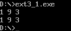
After the source program runs, the result is:
question answering
① line27, when the assembly instruction loop s1 jumps, it jumps according to the displacement. Check the machine code through debug disassembly,
Analyze the displacement of its jump? (the displacement value is answered in decimal) from the perspective of CPU, explain how it is calculated
To the offset address of the instruction after the jump label s1.
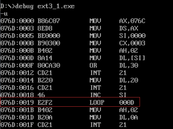
1) Disassemble and check the machine code. You can see that the machine code is E2F2
E2 indicates LOOP
F2 is the displacement in the form of complement, which is converted into binary to 11110010
The original code is 10001110 = − 14, so its displacement is − 14.
2) The CPU obtains the displacement by subtracting the current offset address from the target offset address. The ip of the current instruction is 0019h, that is, 25, 25 − 14 = 11
The length of the previous instruction needs to be added. The offset address of the previous instruction is 11 and the length of the previous instruction B402 is 2 bytes. Therefore, the offset of s1 is calculated as 11 + 2 = 13
② line44. When the assembly instruction loop s2 jumps, it jumps according to the displacement. Check the machine code through debug disassembly,
Analyze the displacement of its jump? (the displacement value is answered in decimal) from the perspective of CPU, explain how it is calculated
To the offset address of the instruction after the jump label s2.
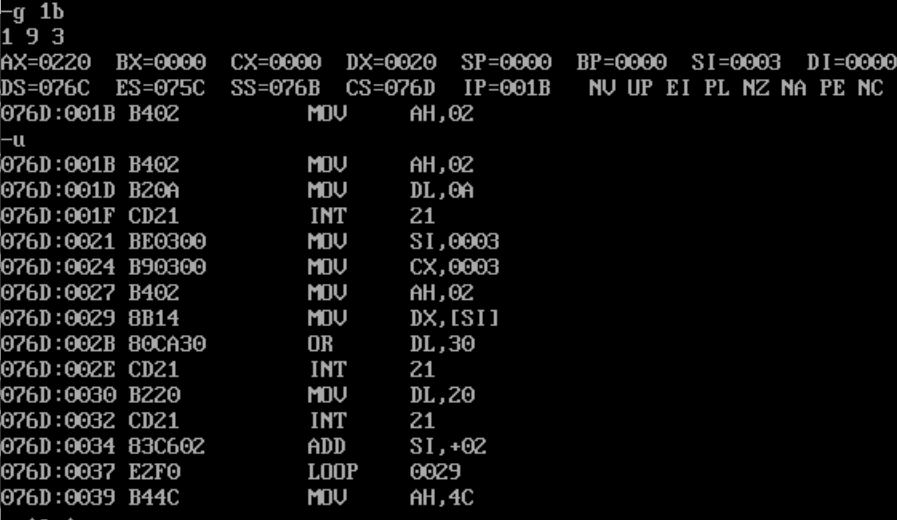
We first run to the first loop and then disassemble it. Like the above calculation method, ip points to 0037h, which is 55, and the complement F0 is converted to the source code of 00010000, that is, the 16 offset address is 55-16 = 39, while the length of the previous instruction B402 is 2 bytes, so the offset of s1 is calculated as 39 + 2 = 41
③ Attach the disassembly screenshot of debugging observation in debug during the above analysis
2. Experimental task 2
taska.asm:
assume cs:code, ds:data
data segment
    dw 200h,0h,230h,0h
data ends

stack segment
    db 16 dup(0)
stack ends

code segment
start:
    mov ax,data
    mov ds,ax

    mov word ptr ds:[0],offset s1
    mov word ptr ds:[2],offset s2
    mov ds:[4],cs

    mov ax,stack
    mov ss,ax
    mov sp,16

    call word ptr ds:[0]
    ;push ip
    ;jmp word ptr ds:[0]
s1: pop ax
    ;(ax) = stack.top() = offset line23 + size(line23) = offset s1
    call dword ptr ds:[2]
    ;push cs
    ;push ip
    ;jmp dword ptr ds:[2]
s2: pop bx
    ;(bx) = stack.top() = offset line28 + size(line28) = offset s2
    pop cx
    ;(bx) = stack.top() = cs = code
    mov ah,4ch
    int 21h
code ends
end start
Question 1
call word ptr ds:[0] short transfer, push the offset address (ip) of the next instruction into the stack and transfer it to ds:[0] address, i.e. s1, and then pop ax will stack the content to ax;
call dword ptr ds:[2] inter segment transfer, push the base address and offset address (cs and ip) of the next instruction into the stack and transfer to the address pointed by the double word starting from ds:[2], that is, s2. After that, pop bx will stack ip to ax and pop cx will stack cs to cx
Namely:
(ax) = offset s1
(bx) = offset s2
(cx) = cs = code
Question 2
Code debugging

After the first call, it can be seen that the code after s1 is indeed executed, and the value of ax is indeed the offset of the address marked by s1
Continue down
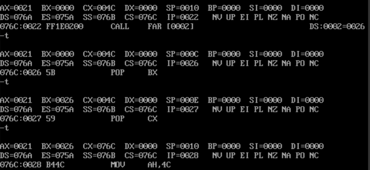
After executing the second call and running pop twice, it can be seen that the code after s2 is indeed executed after the second call, and the value of bx is indeed the offset of the s2 tag address, and cx is indeed the address of the current code segment, that is, the content in the cs register
3. Experimental task 3
For 8086 CPU, the known logical segment is defined as follows:
data segment
	x db 99, 72, 85, 63, 89, 97, 55
	len equ $- x
data ends
Write the 8086 assembly source program task3.asm to output this group of continuous data in the data section in decimal form on the screen, and the data is separated by spaces.
requirement:
-
Write subroutine printNumber
Function: output a two digit number in decimal form
Entry parameter: register ax (data to be output -- > ax)
Outlet parameters: None -
Write the subroutine printSpace
Function: print a space
Entry parameters: None
Outlet parameters: None
In the main code, the addressing mode and loop are comprehensively applied, and printNumber and printSpace are called to realize the subject requirements.
Implementation code:
task3.asm:
assume cs:code, ds:data
data segment
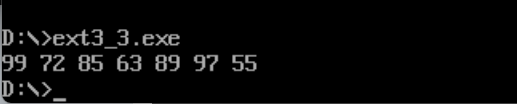
x db 99, 72, 85, 63, 89, 97, 55
len equ $- x
data ends
code segment
main:
mov ax, data
mov ds, ax
mov cx, len
mov si, offset x
print:
mov al, [si]
mov ah, 0
call printNumber
call printSpace
inc si
loop print
mov ah, 4ch
int 21h
;Function: output a two digit number in decimal form
;Entry parameter: Register ax(Data to be output --> ax)
;Outlet parameters: None
printNumber:
mov bl, 10
div bl
mov bx, ax
mov ah, 2
mov dl, bl ; Printer(10 position)
or dl, 30h
int 21h
mov dl, bh ; Print remainder(Bit)
or dl, 30h
int 21h
ret
printSpace:
mov ah, 2
mov dl, ' '
int 21h
ret
code ends
end main
The operation effect is as follows:
4. Experimental task 4
For 8086 CPU, the known logical segment is defined as follows:
data segment
	str db 'try'
	len equ $ - str
data ends
Write 8086 assembly source program task4.asm, specify the color and line on the screen, and output the string on the screen.
requirement:
- Write subroutine printStr
- Function: display the string on the screen in the specified line and in the specified color
- Entry parameters
- The address of the first character of the string -- > ds: Si (where, the segment address of the segment where the string is located -- > DS, and the offset address of the starting address of the string -- > SI)
- String length -- > CX
- String color -- > bl
- Specified line -- > BH (value: 0 ~ 24)
- Outlet parameters: None
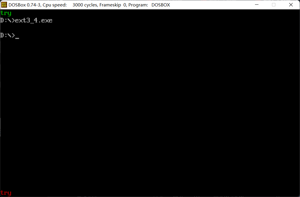
- In the main code, printStr is called twice to display the string in green on a black background at the top of the screen and in black at the bottom of the screen
The string is displayed in red at the bottom
Implementation code:
task4.asm:
assume cs:code
data segment
	str db	'try'
	len equ	$ - str
data ends
code segment
	main:
		mov ax, 0b800h
		mov es, ax

	first_print:
		mov ax, data
		mov ds, ax
		mov si, offset str
		mov cx, len
		mov bl, 00000010b	; Green characters on black background
		mov bh, 0			; Line 0
		call printStr

	second_print:
		mov si, offset str
		mov cx, len
		mov bl, 00000100b	; Scarlet letter on black background
		mov bh, 24			; Line 24
		call printStr

		mov ah, 4ch
		int 21h

	; Entry parameters:
  	;	First character address of string --> ds:si(Where, the segment address of the segment where the string is located -> ds, Offset of string start address -> si)
  	;	String length --> cx
  	;	String color --> bl
  	;	Specify row --> bh (Value: 0 ~24)
	printStr:
		push bp						; Because you need bp and di, Save the scene first
		push di

		mov ah, 0
		mov al, 160
		mul bh
		mov bp, ax					; The offset address for calculating the number of rows is stored in bp
		mov di, si					; di Store the offset address of each character in the video memory
		printChar:
			mov al, ds:[si]
			mov es:[bp+di], al		; character
			mov es:[bp+di+1], bl	; colour
			inc si
			inc di
			inc di					; di It needs to be added twice
			loop printChar

		pop bp						; Restore site
		pop di
		ret

code ends
end main
Operation results:
5. Experimental task 5
For 8086CPU, for 8086CPU, the known logical segment is defined as follows:
data segment
stu_no db '20498329042'
len = $ - stu_no
data ends
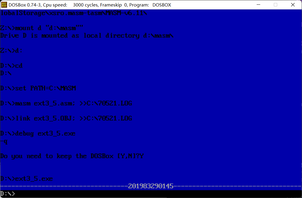
At 80 × In 25 color character mode, the student number is displayed in the middle of the last line of the screen. It is required to output the blue background, student number and broken lines on both sides of the window to
White foreground color display.
Implementation code:
assume cs:code, ds:data
data segment
	stu_no db '201983300514'
	len = $ - stu_no
data ends

code segment
	main:
		call print_blue_screen
		call print_stu_no

		mov ah, 4ch
		int 21h
	print_blue_screen:
		push ax		; Save the site
		push es
		push si

		mov ax, 0b800h
		mov es, ax
		mov cx, 2000
		mov si, 1
		single_blue:
			mov byte ptr es:[si], 00010000b
			inc si
			inc si
			loop single_blue

		pop si		; Restore site
		pop es
		pop ax
	ret

	print_stu_no:
		push ax
		push es
		push si
		push ds
		push di
	prefix:
		mov ax, 0b800h
		mov es, ax
		mov cx, 34
		mov si, 3840	; si Store the offset address of each video memory output
		call print_dash
	content:
		mov ax, data
		mov ds, ax
		mov cx, len
		mov di, 0		; di deposit data Offset address of each character in
		single_no:
			mov al, ds:[di]
			inc di
			mov byte ptr es:[si], al
			inc si
			mov byte ptr es:[si], 00010111b
			inc si
			loop single_no
	postfix:
		mov cx, 34
		call print_dash

		pop di
		pop ds
		pop si
		pop es
		pop ax
	ret

	; input parameter :
	;	Base address displayed si
	;	Output length cx
	; output:
	;	Base address after iteration si
	print_dash:
		single_dash:
			mov byte ptr es:[si], '-'
			inc si
			mov byte ptr es:[si], 00010111b
			inc si
			loop single_dash
	ret

code ends
end main
Experimental results:
Experimental summary
In this experiment, I understand the principle of loop instruction and the principle of call and ret, and I am familiar with the ability of call and ret instruction to encapsulate and reuse code blocks. I can encapsulate part of the code by using tag and ret, and call this code through call instruction, so as to avoid code duplication and redundancy and save code writing time. I also learned a lot about displaying characters on the dos command line. I can display the characters I want to display in any color at any position on the command line. In addition, I learned to write content to video memory to format output characters.