IV. experimental summary
1. Experimental task 1
- The source code of the program is as follows
assume cs:code, ds:data

data segment
    x db 1, 9, 3
    len1 equ $ - x

    y dw 1, 9, 3
    len2 equ $ - y
data ends

code segment
start:
    mov ax, data
    mov ds, ax

    mov si, offset x
    mov cx, len1
    mov ah, 2
 s1:mov dl, [si]
    or dl, 30h
    int 21h

    mov dl, ' '
    int 21h

    inc si
    loop s1

    mov ah, 2
    mov dl, 0ah
    int 21h

    mov si, offset y
    mov cx, len2/2
    mov ah, 2
 s2:mov dx, [si]
    or dl, 30h
    int 21h

    mov dl, ' '
    int 21h

    add si, 2
    loop s2

    mov ah, 4ch
    int 21h
code ends
end start
- The screenshot of the operation is as follows
-
- Answer question ①
-
line27, Assembly instruction loop s1 When jumping, it jumps according to the displacement. adopt debug Disassemble, check its machine code, and analyze the displacement of its jump? (the displacement value is answered in decimal) CPU Angle, description
 How to calculate the post jump label s1 The offset address of the subsequent instruction.
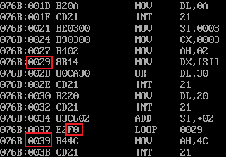
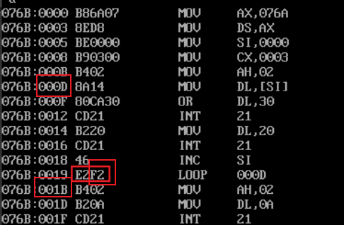
- The disassembly results are as follows
- The jump displacement is 14
- The method of calculating the offset address of the instruction after the jump label s1 is as follows
- Observe the machine code E2F2 corresponding to the Loop command
- An assembly statement will correspond to a machine code, which is divided into two parts
- Assembly instructions correspond to the first two hexadecimal numbers
- The number of hexadecimal digits after the operand
- For loop, the operand is the difference between the address of the beginning of the loop and the address of the next instruction of the loop instruction, and is presented in the form of complement
- Therefore, the formula can be obtained
- The address at the beginning of the loop = the address of the next instruction of the loop instruction + the difference between the addresses
- An assembly statement will correspond to a machine code, which is divided into two parts
- According to the formula, the offset address of the instruction after the jump label s1 needs to be solved, and two information needs to be known
- loop instruction the address of the next instruction
- The operand of the loop instruction machine code
- In this question
- The address of the next instruction of the loop instruction is 001B, which is 27 when converted to decimal
- The operand of the loop instruction machine code is F2 (complement), i.e. 11110010 (complement). The original code is 10001110, which is converted to decimal - 14
- Therefore, the address at the beginning of the cycle is 27 + (- 14) = 13, that is, 000D
- The above is how the CPU calculates the location of the instruction after s1
- Observe the machine code E2F2 corresponding to the Loop command
-
- Answer question ②
- Similar to question ①, first observe the result of disassembly
- Calculate two numbers
- The position of the next instruction of the loop instruction is (0039) 16 = (57) 10
- The operand of the loop instruction machine code is F0, that is, 11110000, and the original code is 10010000, that is - 16
- 57-16=41, (41)10=(29)16
- After calculation, the result is the same as that of disassembly
- The above is the process of the CPU calculating the instruction position after s2
2. Experimental task 2
- The program source code is as follows
-
 1     assume cs:code, ds:data
 2
 3     data segment
 4         dw 200h, 0h, 230h, 0h
 5     data ends
 6
 7     stack segment
 8         db 16 dup(0)
 9     stack ends
10
11     code segment
12     start:
13         mov ax, data
14         mov ds, ax
15
16         mov word ptr ds:[0], offset s1
17         mov word ptr ds:[2], offset s2
18         mov ds:[4], cs
19
20         mov ax, stack
21         mov ss, ax
22         mov sp, 16
23
24         call word ptr ds:[0]
25     s1: pop ax
26
27         call dword ptr ds:[2]
28     s2: pop bx
29         pop cx
30
31         mov ah, 4ch
32         int 21h
33     code ends
34     end start
- Problem: according to the jump principle of call instruction, theoretically, before the program is executed and exits (line31), register ax=?, bx=?, cx=?
- The thinking process is as follows
- First, you need to know the function of the call instruction
- Press the address of the next instruction of the program into the stack (that is, press the address in the program counter pc into the stack)
- Execute the instruction of the address marked after call (change the value in pc to the address after call)
- Put the data in ds:[2] into the pc in this question
- The role of call word ptr a
- Push the address of the next instruction onto the stack
- jump to the address of the following label a
- call dword ptr a
- Press the segment address and intra segment offset of the next instruction into the stack in turn
- jump to the address of the following label a
- Second, you need to understand the program
- data segment and stack segment define a series of data
- The program to be executed is written in code segment
- line13-14: send the address value of data segment into ds
- line16: sends the address of the code segment s1 to ds:[0] and ds:[1] for later calls.
- line17: sends the address of the code segment s2 to ds:[2] and ds:[3] for later calls.
- line18: enter the address of cs into ds:[4]
- line20-22: set stack bottom and top pointers
- line20-21: send the address value of stack segment into ss, indicating that the address at the bottom of the stack is the address pointed to by stack segment
- line22: send 16 to sp, indicating that the position of the top element of the stack is ss:sp
- line24: call the instructions in ds:[0] and ds:[1], which are divided into two stages
- Push the offset address in the segment where the next instruction is located into the stack
- Set the value of pc to the data in ds:[0]
- line25: pop up the stack top element and store it in ax
- Because line24 has a stack operation just now, the content just pressed in should pop up at this time, that is, the address of s1
- line27: call the corresponding instructions in ds:[2],ds[3],ds:[4],ds:[5], which is divided into two stages
- Press the segment address and offset address of the next instruction into the stack in turn
- Set the value of pc to the data in ds:[2]
- line28: pop up the stack top element and store it in bx
- Just now line27 presses the segment address and the intra segment offset of the address where the s2 code segment is located into the stack in turn, so the top of the stack is the offset address of s2
- line29: pop up the stack top element and store it in cx
- At this time, the top element of the stack is the segment address of s2
- While reading the program, I know the answer to the question
- Because cs:ip points to the address of the currently executing code, the
- ax stores the intra segment offset address part of the address of s1 code segment, that is, the value in the ip register when call word ptr ds:[0] is executed
- bx stores the intra segment offset address part of the address of the s2 code segment, that is, the value in the ip register when call dword ptr ds:[2] is executed
- The segment address part of the address of the s2 code segment is stored in cx, that is, the value stored in cs when call dword ptr ds:[2] is executed
- Because cs:ip points to the address of the currently executing code, the
- First, you need to know the function of the call instruction
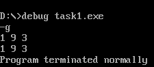
- Practical verification
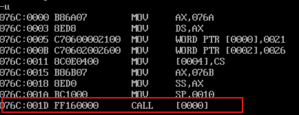
- First look at the disassembly results
- View the address of the call instruction, 001d
- Run the program to the call word ptr ds:[0] command, and the operation is completed
- The value of ax is indeed the value of ip 0021
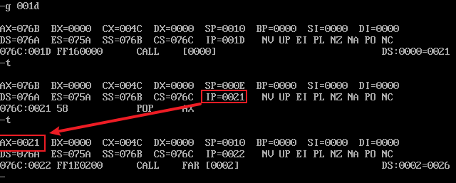
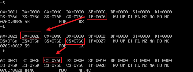
- Run the program to the call dword ptr ds:[2] command. The operation is completed
- The value of bx is indeed the value of ip
- The value of cx is indeed the value of cs
- View the address of the call instruction, 001d
- After verification, this question ends
- First look at the disassembly results
3. Experimental task 3
- At the beginning of the experiment, you need to know the following information
- Memory principle for outputting characters on the screen
- Numerical values are stored in the computer in binary form
- If the value 12666 is stored in the computer, it is 0011000101111010B(317AH)
- The computer can understand this string of data
- The numbers we see printed on the screen are presented in ASCII code
- For example, the value 12666, if you want them to be displayed on the screen, the storage in the computer should be 31H,32H,36H,36H,36H
- If you want to see the value on the screen, you should convert the binary number in the computer to its corresponding ASCII code
- ASCII code only defines the representation corresponding to 0-9
- Therefore, when processing values, they should be processed bit by bit
- For example, if the value is 12666, take one bit (divide by ten to get the remainder), turn it into character 6, then process 1266, and so on
- Numerical values are stored in the computer in binary form
- Assembly instructions for outputting characters on the screen
- The instruction int 21h is a multifunctional instruction
- During execution, the value of register AH will be checked first, and different operations will be carried out according to different values
- When AH=02H, output the characters in DL to the screen
- During execution, the value of register AH will be checked first, and different operations will be carried out according to different values
- The instruction int 21h is a multifunctional instruction
- About division instructions
- div instruction is a division operation instruction
- Instruction format
- div register
- Instruction operation process (take div bx as an example)
- The dividend is placed in register AX
- The divisor is stored in the register following the instruction div
- The supplier is stored in AL
- The remainder is placed in AH
- Method for converting numbers to corresponding ASCII codes
- ASCII code corresponding to decimal digit character = decimal digit value + 30H
- Memory principle for outputting characters on the screen
- With the above information, begin to conceive the problem
- Title restatement
- Seven two digit decimal numbers are stored in the memory and need to be printed on the screen
- thinking
- The values stored in the memory need to be printed on the screen
- So you need to convert these 7 numbers bit by bit into ASCII code
- Taking 99 as an example, the steps of operating on a number are as follows
- Take out a digit number -- 9
- Convert 9 to its corresponding ASCII code (above the formula)
- Printout
- Take out ten digits -- 9
- Convert 9 to its corresponding ASCII code '
- Printout
- For the above steps, perform the following operations (PrintNumber)
- Carry out 99 / 10 operation. (the remainder obtained is stored in AH by default)
- Carry out "+ 30H" operation on AH, and use the formula to calculate the ASCII code value corresponding to the remainder
- Store the calculated ASCII code value in dl for output
- Output with int 21
- Repeat operations 1, 2 and 3 to output ten digits
- Complete a digital output
- Printing spaces is relatively simple and will not be repeated
- The values stored in the memory need to be printed on the screen
- code implementation
-
 1 assume cs:code, ds:data
 2
 3 data segment
 4     x db 99, 72, 85, 63, 89, 97, 55
 5     len equ $- x    ;Align the current location with x Position difference len in,len=7
 6 data ends
 7
 8 code segment
 9 start:
10     mov ax, data    ;take x Start address of si in
11     mov ds, ax
12     mov si, offset x
13     mov cx,len
14
15 s1: call printNumber
16     call printSpace
17     inc si
18     loop s1
19
20     mov ah, 4ch
21     int 21h
22 printNumber:
23     mov ah,00
24     mov al, ds:[si] ;take si The value corresponding to the address is put into ax in,Act as divisor.For division
25     mov bl, 10  ;Put 10 in bx in,Act as divisor,For division
26     div bl      ;division
27     or al, 30h  ;General quotient(Ten digit part of the original value)Turn to corresponding ASCII Code value
28     mov dl, al  ;Corresponding to the value of quotient ASCII Value put dl in,For output
29
30     or ah, 30h  ;Remainder(Bit part of the original value)Turn to corresponding ASCII Code value
31     mov bh,ah   ;Remainder(Bit part of the original value)Turn to corresponding ASCII Code value stored in bh in,Because it needs to be modified below ah Value of,by int 21h Prepare,So we have to put it somewhere else first
32
33     mov ah,2
34     int 21h     ;Output ten digits of the original value
35
36     mov dl, bh
37     mov ah,2
38     int 21h     ;Output bit
39
40     ret         ;Returns the place where the function was called
41
42 printSpace:
43     mov dl,' '  ;Move empty characters into dl in,For output
44     mov ah,2
45     int 21h
46     ret
47
48
49 code ends
50 end start
-
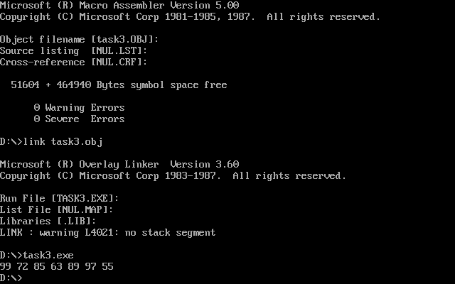
- The operation results are as follows
- Title restatement
-
4. Experimental task 4
- Before the experiment, we need to know the following information
- There is a special area in the memory address space into which writes are immediately displayed on the screen
- The address range of this area is B8000H-BFFFFH
- The area name is 80 * 25 color character mode display buffer
- It is generally expressed in the form of B800:0000
- The characteristics of 80 * 25 color character mode display buffer are as follows
- A character occupies two bytes of space (generally, one character occupies one byte)
- In the occupied byte, the upper eight bits are color information and the lower eight bits are ASCII code
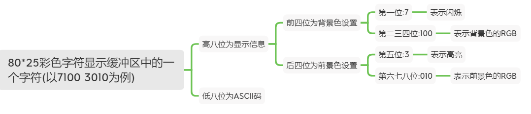
- According to the above characteristics, you can write
- It is written in green on a red background, and the upper eight digits are 01000010B
- White characters on black background, eight digits high, 00000111B
- Red letter on black background, with eight high digits of 00000100B
- Green characters on black background, eight digits high, 00000010B
- Line information
- Each line has 80 characters. Because a character in this space occupies two bytes, a line occupies a total of 160 bytes
- The offset address of the first line is 000-009F
- The offset address of the second line is 0A0-13F
- And so on, the offset address of the last line is F00-F9F
- Each line has 80 characters. Because a character in this space occupies two bytes, a line occupies a total of 160 bytes
- There is a special area in the memory address space into which writes are immediately displayed on the screen
- With the above information, begin to conceive the code of this problem
- Title restatement
- The red character string on a black background is displayed at the top of the screen, and the green character string on a black background is displayed at the bottom of the screen
- thinking
- To display a colored string, you need to write data to B8000-BFFFF
- The string is displayed at the top, and data needs to be written from B800:0000
- The string is displayed at the bottom. You need to write data from B800:0F00
- The written data should be an ASCII code + a display information, cyclic input
- With ideas, the code is very easy to write. The code is as follows
 1 assume cs:code, ds:data
 2 data segment
 3     str db 'try'
 4     len equ $- str
 5 data ends
 6
 7 code segment
 8 start:
 9     mov ax,data
10     mov ds,ax
11
12     mov si,offset str
13     mov cx, len
14     mov bl, 00000010B   ;Save color information---Black background green
15     mov bp, 00          ;Save the position of the first line
16     mov ax, 0B800H      ;80*25 Segment address of color character display area
17     mov es, ax
18
19 s1: call printStr
20     loop s1
21
22     mov bl,00000100B    ;Save color information---Red on black background
23     mov bp,0F00H         ;Save position of last line
24     mov cx,len          ;Set the number of cycles
25     mov si,offset str
26
27 s2: call printStr
28     loop S2
29
30     mov ah, 4ch
31     int 21h
32
33
34 printStr:
35     mov ax, ds:[si]
36     mov es:[bp],ax
37     inc bp
38     inc si
39     mov es:[bp],bl
40     inc bp
41
42     ret
43
44
45 code ends
46 end start
- The operation results are as follows
- Title restatement
- Before the experiment, we need to know the following information
-
5. Experimental task 5
- The basic knowledge part is the same as experimental task 4. The difficulty of this problem is to calculate the starting position of student number string
- Because one line can display 80 characters, our student number has 12 characters
- To display the student number in the middle, you need to leave (80-12) / 2 = 34 characters on the left
- These 34 characters occupy 2 bytes per character in the 80 * 25 color character display space
- So it takes up 68 bytes, that is, 44H bytes
- The offset address at the beginning of the last line is 0F00H, so the offset address at the beginning of the student number is 0F44H
- The program design idea is as follows
- The whole consists of three cycles
- The loop turns the screen to a blue background
- The loop makes the last line a horizontal line (minus sign)
- Loop so that the student number is displayed in the middle of the last line
- The whole consists of three cycles
- With ideas, the program design is very simple
- s1 corresponds to the first cycle
- s2 corresponds to the second cycle
- s3 corresponds to the third cycle, and the code is as follows
 1 assume ds:data, cs:code
 2 data segment
 3     stu_no db '201983290203'
 4     len equ $ - stu_no
 5 data ends
 6
 7 code segment
 8 start:
 9     mov ax,data
10     mov ds,ax
11
12     mov si,offset stu_no
13
14     mov cx,2000
15
16     mov bl,00010000B
17     mov ax,0B800H
18     mov es,ax
19     mov bp,00
20
21 s1: inc bp
22     mov es:[bp],bl
23     inc bp
24     loop s1         ;s1 Cycle sets the interface to blue
25
26     mov bp,0F00H
27     mov bl,00010111B
28     mov cx,80
29
30 s2: mov ax, 45      ;Horizontal line/Minus sign ASCII Code 45
31     mov es:[bp], ax
32     inc bp
33     mov es:[bp],bl
34     inc bp
35     loop s2
36
37     mov ax,data
38     mov ds,ax
39     mov si,offset stu_no
40     mov bp,0F44H
41     mov cx, len
42
43 s3: mov ax, ds:[si]
44     mov es:[bp],ax
45     inc si
46     inc bp
47     mov es:[bp],bl
48     inc bp
49     loop s3
50
51 code ends
52 end start
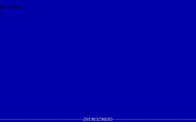
- The operation results are as follows
- The basic knowledge part is the same as experimental task 4. The difficulty of this problem is to calculate the starting position of student number string
- Experience has been given in detail in the blog, thank you!