Experimental task 1
The source code of task1 is as follows:
 1 assume cs:code, ds:data
 2
 3 data segment
 4     x db 1, 9, 3
 5     len1 equ $ - x
 6
 7     y dw 1, 9, 3
 8     len2 equ $ - y
 9 data ends
10
11 code segment
12 start:
13     mov ax, data
14     mov ds, ax
15
16     mov si, offset x
17     mov cx, len1
18     mov ah, 2
19  s1:
20     mov dl, [si]
21     or dl, 30h
22     int 21h
23
24     mov dl, ' '
25     int 21h
26
27     inc si
28     loop s1
29
30     mov ah, 2
31     mov dl, 0ah
32     int 21h
33
34     mov si, offset y
35     mov cx, len2/2
36     mov ah, 2
37  s2:
38     mov dx, [si]
39     or dl, 30h
40     int 21h
41
42     mov dl, ' '
43     int 21h
44
45     add si, 2
46     loop s2
47
48     mov ah, 4ch
49     int 21h
50 code ends
51 end start
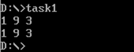
The screenshot of the operation result is as follows:
Question answer:
① Q: when the line27 assembly instruction loop s1 jumps, it jumps according to the displacement. Check the machine code through debug disassembly and analyze the jump displacement? (the displacement value is answered in decimal) from the perspective of the CPU, explain how to calculate the offset address of the instruction after the jump label s1.
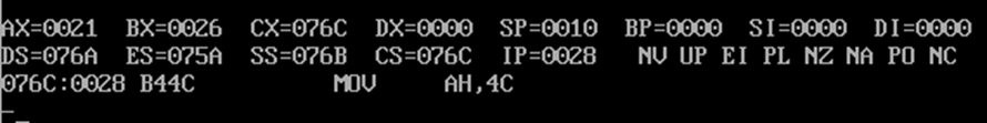
A: check the screenshot of the corresponding machine code through debug disassembly as follows:
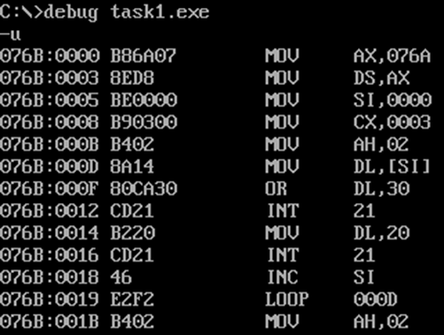
As can be seen from the figure, the jump displacement of the loop s1 instruction is - 14, which is obtained by subtracting the first byte address (i.e. 076b: 001b) after the loop s1 instruction from the address (i.e. 076b: 000d) at the s1 label. For the CPU, the displacement is expressed in the form of complement.
② Q: line44, when the assembly instruction loop s2 jumps, it jumps according to the displacement. Check the machine code through debug disassembly and analyze the jump displacement? (the displacement value is answered in decimal) from the perspective of the CPU, explain how to calculate the offset address of the instruction after the jump label s2.
A: check the screenshot of the corresponding machine code through debug disassembly as follows:
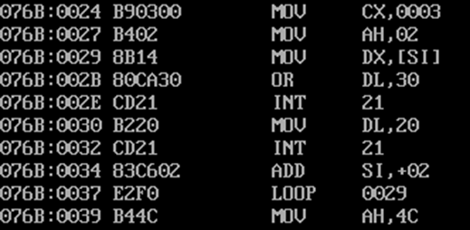
As can be seen from the figure, the jump displacement of loop s1 instruction is - 16, which is obtained by subtracting the first byte address (076B: 0029) after loop s1 instruction from the address (076B: 0039) at s2 label. For CPU, the displacement is expressed in the form of complement.
③ Attach the disassembly screenshot of debugging observation in debug during the above analysis.
A: the disassembly screenshots are shown in the screenshots given in question ① and question ②.
Experimental task 2
- The source code of task2.asm is as follows:
 1 assume cs:code, ds:data
 2
 3 data segment
 4     dw 200h, 0h, 230h, 0h
 5 data ends
 6
 7 stack segment
 8     db 16 dup(0)
 9 stack ends
10
11 code segment
12 start:
13     mov ax, data
14     mov ds, ax
15
16     mov word ptr ds:[0], offset s1
17     mov word ptr ds:[2], offset s2
18     mov ds:[4], cs
19
20     mov ax, stack
21     mov ss, ax
22     mov sp, 16
23
24     call word ptr ds:[0]
25 s1:
26     pop ax
27
28     call dword ptr ds:[2]
29 s2:
30     pop bx
31     pop cx
32
33     mov ah, 4ch
34     int 21h
35 code ends
36 end start
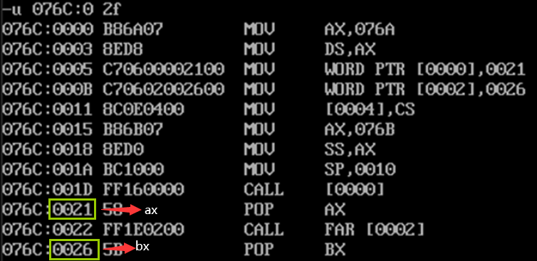
- The screenshot of the debugging result interface is as follows:
- Question answer:
① Q: according to the jump principle of call instruction, first analyze theoretically that before the program executes to exit (line31), register (ax) =? Register (bx) =? Register (cx) =?
A: theoretically, before the program is executed to exit (line31), register (AX) = the offset address of the first byte after call S1 instruction, register (BX) = the offset address of the first byte after call S2 instruction, and register (Cx) = the address of CS segment.
② Q: assemble and link the source program to get the executable program task2.exe. Use debug to observe and verify whether the debugging results are consistent with the theoretical analysis results.
A: from the screenshot of the debugging result interface given above, it can be seen that the debugging result is consistent with the theoretical analysis result.
Experimental task 3
The program source code task3.asm is as follows:
 1 assume cs:code, ds:data, ss:stack
 2
 3 data segment
 4     x db 99, 72, 85, 63, 89, 97, 55
 5     len equ $- x
 6 data ends
 7
 8 stack segment
 9     dw 8 dup (0)
10 stack ends
11
12 code segment
13 start:
14     mov ax, data
15     mov ds, ax
16     mov ax, stack
17     mov ss, ax
18     mov sp, 16
19
20     mov di, 0
21     mov cx, 7
22 s:    mov al, ds:[di]
23     mov ah, 0
24     call printNumber
25     call printSpace
26     inc di
27     loop s
28
29     mov ah, 4ch
30     int 21h
31 printNumber:
32     mov bl, 10
33     div bl
34     mov bx, ax
35     or bx, 3030h
36     mov ah, 2
37     mov dl, bl
38     int 21h
39     mov ah, 2
40     mov dl, bh
41     int 21h
42     ret
43 printSpace:
44     mov ah, 2
45     mov dl, ' '
46     int 21h
47     ret
48 code ends
49 end start
The screenshot of running test is as follows:
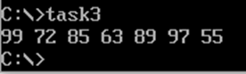
It can be seen that the program successfully realizes the functions required by the experiment.
Experimental task 4
The program source code task4.asm is as follows:
 1 assume cs:code, ds:data, ss:stack
 2
 3 data segment
 4     str db 'try'
 5     len equ $ - str
 6 data ends
 7
 8 stack segment
 9     dw 8 dup (0)
10 stack ends
11
12 code segment
13 start:
14     mov ax, data
15     mov ds, ax
16     mov ax, stack
17     mov ss, ax
18     mov sp, 16
19     mov ax, 0b800h
20     mov es, ax
21
22     mov bh, 0
23     mov bl, 2
24     call printStr
25
26     mov bh, 24
27     mov bl, 4
28     call printStr
29
30     mov ah, 4ch
31     int 21h
32 printStr:
33     mov ah, 0
34     mov al, 160
35     mul bh
36     mov di, ax
37
38     mov cx, len
39     mov si, 0
40
41 s:  mov al, ds:[si]
42     mov es:[di], al
43     mov es:[di+1], bl
44     add di, 2
45     inc si
46     loop s
47
48     ret
49 code ends
50 end start
The screenshot of running test is as follows:

It can be seen that the program successfully realizes the functions required by the experiment.
Experimental task 5
The program source code task5.asm is as follows:
 1 assume cs:code, ds:data
 2
 3 data segment
 4     stu_no db '201983290186'
 5     len = $ - stu_no
 6 data ends
 7
 8 code segment
 9 start:
10     mov ax, data
11     mov ds, ax
12     mov ax, 0b800H
13     mov es, ax
14
15     mov di, 0
16     mov cx, 2000
17 s:  mov byte ptr es:[di+1], 17h
18     add di, 2
19     loop s
20
21     mov al, 160
22     mov bl, 24
23     mul bl
24     mov di, ax
25     mov cx, 80
26 s1: mov byte ptr es:[di], '-'
27     add di, 2
28     loop s1
29
30     mov bx, 80-len
31     mov di, ax
32     mov si, 0
33     mov cx, 12
34 s2: mov al, [si]
35     mov es:[di+bx], al
36     inc si
37     add di, 2
38     loop s2
39
40     mov ah, 4ch
41     int 21h
42 code ends
43 end start
The screenshot of running test is as follows:
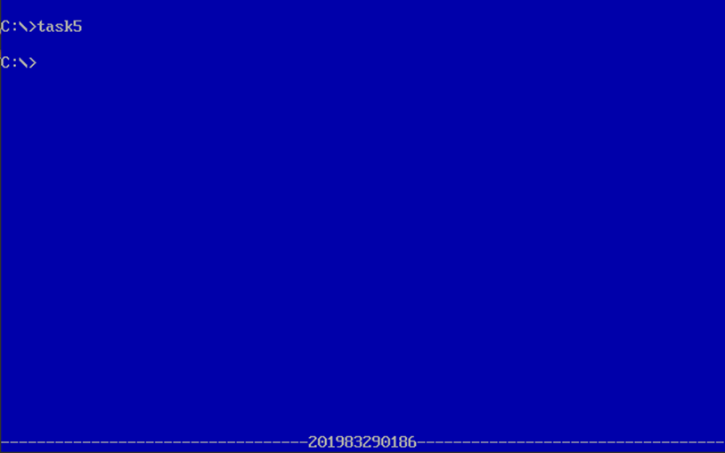
It can be seen that the program successfully realizes the functions required by the experiment.