Introduction: Taking the 16th "NXP Cup" national college student smart car competition as the background, this paper introduces the smart car technical achievements of Chinese workers Yuhua team in the energy-saving beacon group of the competition. This paper will start from the mechanical structure design of intelligent vehicle, hardware circuit design, camera light search algorithm, intelligent vehicle control algorithm and wireless charging, and elaborate the design ideas and creativity of our group in detail, reflecting our unique ideas in algorithm and hardware.
Our group adopted the three wheel scheme and made its own car model. The processor uses TC264 single chip microcomputer of Infineon company and is developed under ADS software development environment. The smart car track information acquisition sensor uses a gray camera with an infrared filter. The track deviation information and the vehicle attitude angular speed information obtained by the gyroscope are used to control the direction of the whole vehicle, and the motor encoder is used to obtain the vehicle speed information to control the speed of the vehicle. Position PID control is used for direction control and angle control. The two rear drive wheels of the tricycle are controlled by PWN for differential steering, acceleration and deceleration to realize closed-loop control. In terms of charging, LCC topology is used to harvest radio energy, and five 50 farad capacitor banks are used to store capacitors. In terms of debugging, we designed a human-computer interaction module, which can better debug the parameters of intelligent vehicle and detect the vehicle state. The added wireless communication module can also observe the state parameters of the vehicle in real time, which is helpful to the parameter setting. The image debugging host computer written in C# is used to debug and improve the image algorithm with SD card.
During the epidemic, despite many difficulties, we still overcome all difficulties so that the car can fly on the field. This report commemorates the youth and efforts in preparing for smart cars in the past year.
Key words: energy saving beacon, wireless charging, TC264, gray camera, gyroscope, PID control
Team name: Chinese workers Yuhua team
Contestants: Li Zifeng
Lai Xiang
Su peishuo
Team leader: Chen an
Deng Xiaoyan
Chapter I Introduction
this report will explain in detail the intelligent vehicle system design scheme of our team during the competition. From the mechanical structure design, hardware circuit design, camera light search algorithm, intelligent vehicle control algorithm and wireless charging of intelligent vehicle, this paper will elaborate the design ideas and creativity of our group in detail, reflecting our unique ideas in algorithm and hardware. In the process of preparing for the game, our team has made efforts and shed sweat. This report will condense our efforts and wisdom since preparing for the game. I hope our team's efforts can be recognized and we can continue to work hard to challenge better results and learn more new knowledge.
1.1 introduction to smart car competition
the National College Students' smart car competition is a creative science and technology competition with smart cars as the research object. It is an exploratory engineering practice activity for college students across the country. It is one of the science and technology competitions advocated by the Ministry of education. With the guiding ideology of "based on training, focusing on participation, encouraging exploration and pursuing excellence", the competition aims to promote quality education in Colleges and universities. It takes the task of designing and manufacturing complex engineering problems such as intelligent model vehicles that can drive independently on a specific track and have superior performance as its task. It encourages college students to form a team and comprehensively use multidisciplinary knowledge to put forward, analyze, design, develop and study the mechanical structure, electronic circuits, motion control, development and debugging tools of intelligent vehicles, Stimulate college students' interest and potential in engineering technology development and scientific research and exploration, and advocate the study style of integrating theory with practice, seeking truth and pragmatism and the humanistic spirit of teamwork.
1.2 requirements and tasks of the 16th energy saving beacon group
1.2. 1 car model
models are allowed to use any model in the competition, or they can be designed and made by themselves. The size of car model works is unlimited. No battery is allowed to be used on the car model. The car model needs to obtain the radio energy transmitted by the beacon through the wireless receiving coil. The beacon lamp is flat, and the car model can drive to the beacon to receive radio energy.
1.2. 2 microcontrollers and sensors
the car model uses the single chip microcomputer of Infineon company. It is allowed to use various electromagnetic, infrared photoelectric, camera, laser sensor and ultrasonic sensor devices for track and environmental detection.
1.2. 3 race track and task
after the beacon is lit, it will send high-frequency wireless power signal at the same time (150kHz) and red and infrared lights are used to guide the car model. The transmitted high-frequency wireless power signal can also provide about 72W charging power for the energy-saving car model through electromagnetic resonance coupling. During the competition, the car model receives electric energy from the first beacon and starts to the next beacon by itself. When the car model runs on the beacon, the beacon light switches to the next beacon, but The local beacon still sends radio energy until the model leaves the local beacon, the local beacon stops sending radio energy, and the next beacon starts sending wireless signal.
Chapter II overall framework and scheme design
this chapter will briefly introduce the overall design idea of our group's intelligent vehicle system and briefly explain the technical scheme. In the following chapters, the mechanical structure design, hardware circuit design, camera light search algorithm, intelligent vehicle control algorithm and so on are deeply introduced and analyzed.
2.1 overall scheme of intelligent vehicle
according to the competition requirements and tasks of the 16th smart car competition, our team has made corresponding choices in vehicle model, processor, track information acquisition scheme and vehicle control scheme. In this competition, our car model is a self-made car model, which uses Solidworks software to model the car, and then completes the manufacturing of the car body by 3D printing technology. The processor uses TC264 single chip microcomputer of Infineon company to develop embedded software under the development environment of AURIX Development Studio. The smart car track information acquisition sensor uses a gray camera to install an infrared filter for the camera to obtain the infrared information of the beacon lamp, so as to realize the accurate identification of the beacon lamp. The deviation information of the beacon lamp and the vehicle attitude angular speed information obtained by the gyroscope are used to control the direction of the whole vehicle, and the motor encoder is used to obtain the vehicle speed information to control the speed of the vehicle. Position PID control is used for direction control and angle control. The two rear drive wheels of the tricycle are controlled by PWN for differential steering, acceleration and deceleration to realize closed-loop control. At the same time, the human-computer interaction module is also designed, which can better debug the parameters of the intelligent vehicle and detect the vehicle state. The added wireless communication module can also observe the state parameters of the vehicle in real time, which is helpful to the parameter setting.
2.2 general introduction to each module of intelligent vehicle
the whole vehicle can be divided into the following modules: main control module, sensor module, power management module, motor drive module, human-computer interaction module and communication module.
1. Main control module: Infineon TC264 MCU, which processes and calculates the collected sensor information and controls the motor.
2. Sensor module: gray camera, 9-axis gyroscope accelerometer, motor with encoder. Realize various functions respectively, which are explained in detail in the following chapters.
3. Power management module: provide appropriate voltage power supply for each module.
4. Motor drive module: provides an interface for the processor to control the motor
5. Human computer interaction module: it is composed of IPS screen, keys, dial switch, five way switch, SD card slot and buzzer.
6. Communication module: NRF wireless communication module is adopted to realize the communication between the vehicle and the upper computer as an auxiliary module in the commissioning stage.
Chapter III mechanical structure design of intelligent vehicle
the foundation of intelligent vehicle is the body mechanical structure, and the control program can only be realized on this basis. Therefore, the design of mechanical structure of intelligent vehicle is particularly important for the performance of the whole vehicle. This chapter will explain the mechanical structure in detail.
3.1 overall structure of vehicle model
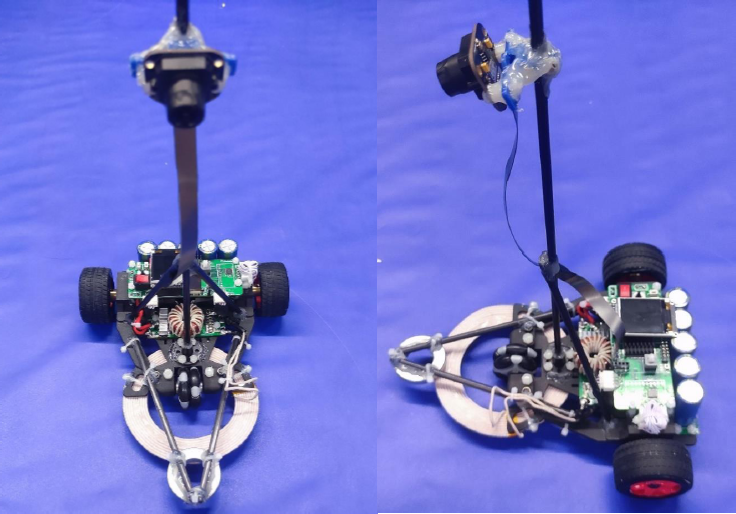
the energy-saving group is different from previous years. Due to the task of beacon, the car model needs to have certain speed requirements, so we adopt the three wheel design to minimize the weight of the car model on the basis of ensuring the speed. At the same time, we also consider the problem of the center of gravity of the car model. In the design, we try to make the center of gravity back and fall on the two rear wheels to improve the steering performance. The overall mechanical structure is shown in the figure below.
3.2 design and installation of sensor
vehicle sensors include: gray camera; 9-axis sensor; Motor encoder.
3.2. 1 installation of gray camera
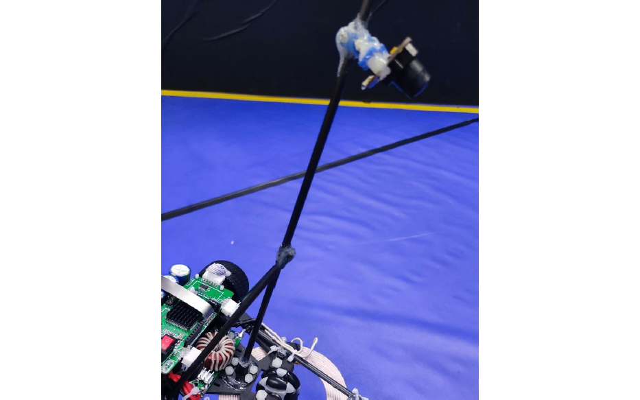
use the triangular structure to erect the camera as shown in the figure.
3.2. 2 installation of attitude sensor
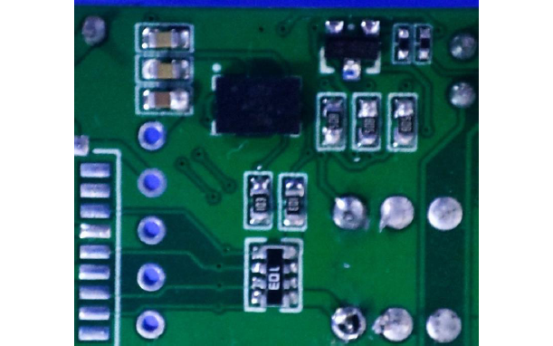
the attitude sensor uses BMX055 sensor to weld the bare chip under the main board PCB.
3.2. 3 encoder installation
the encoder is the encoder provided by the motor and installed on the rear shaft of the motor to obtain the rotation information of the motor.
3.3 fixing and connection of circuit board
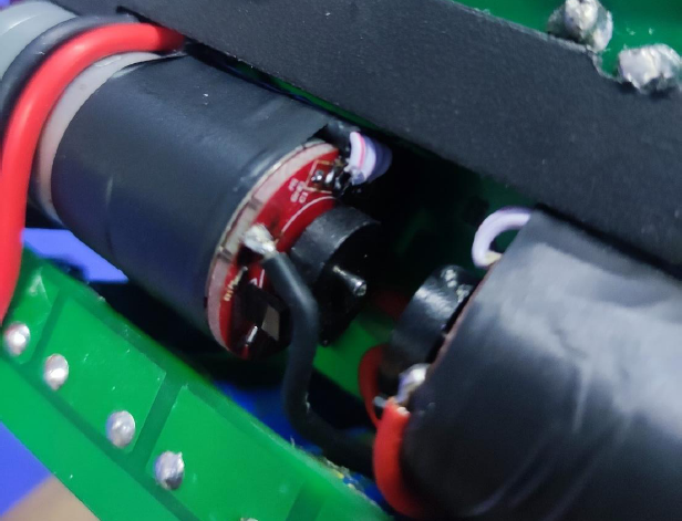
for this model, there are 4 circuit boards in total, including main control board, power drive board, charging board and super capacitor board. The main load-bearing and connecting structure of the car body is composed of two circuit boards, the upper main control board and the lower power drive board. Fixed connection through rubber column. The super capacitor board is installed at the rear of the motor, which reduces the center of gravity through structural design. The charging plate is located at the front of the model and is connected with the charging coil.
3.3. 1 installation of main control board
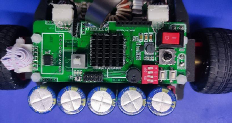
the main control board is the most important circuit board of the whole vehicle body, and it is also the most frequently contacted circuit board in the shunting process. It integrates the functions of switch, IPS, download interface, dial switch, indicator light and so on. Therefore, placing this circuit board on the top layer is undoubtedly the best choice, and it will be more convenient for later debugging and downloading.
3.3. 2 installation of power drive board
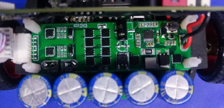
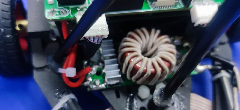
the main function of the power drive board is to increase and decrease the voltage of the super capacitor to 12V for the motor, and control the speed of the motor through the H-bridge circuit to achieve the purpose of controlling the speed of the vehicle model. The board does not need human-computer interaction, so it is reasonable to put it under the main board.
3.3. 3 installation of super capacitor board
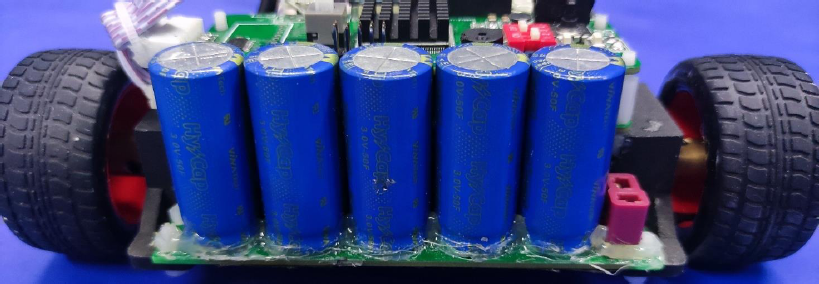
due to the particularity of this year's energy-saving beacon task, we have adopted a 5-SECTION 50 farad super capacitor, which is heavy, so it is installed at the rear of the motor, and its center of gravity is reduced when designing the machine.
3.3. 4 installation of charging board
the charging board is small, so it is installed in the front of the vehicle model and connected with the charging coil. At the same time, it is connected with the super capacitor bank at the rear to supplement electric energy during charging.
3.4 body design and motor installation
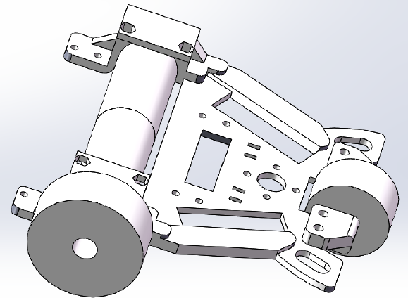
Solidworks is used for the overall design of the vehicle model, and the overall design effect is shown in the figure.
3.4. 1 body design
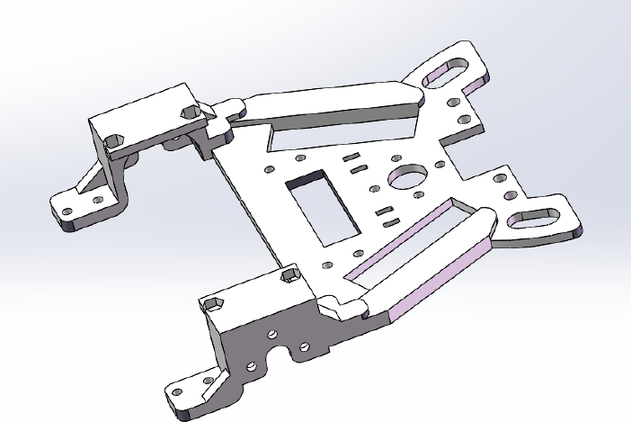
the body is made of 3D printing technology and nylon material. The strength and toughness meet the load strength requirements.
3.4. 2 universal wheel design
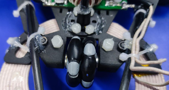
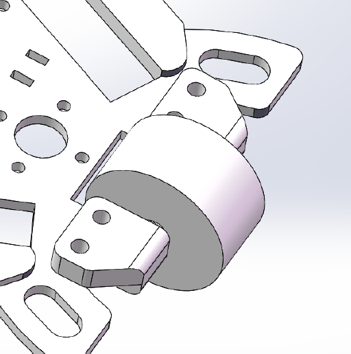
the universal wheel uses the mcnamu wheel of ROTACASTER omni-directional wheel, 35mm black ball and 7mm inner diameter bearing, which is installed in the front of the vehicle model. The installation effect is shown in the figure.
3.4. 3 installation of motor and rear wheel
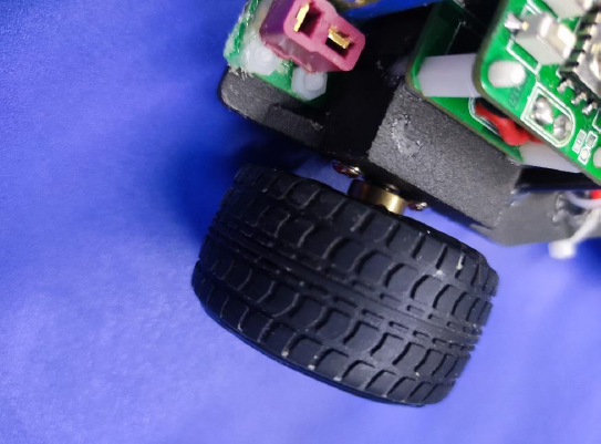
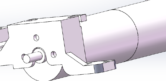
the motor is connected with the print by M3 screw, and the rear wheel is connected with the motor output shaft by A motor coupling. The actual effect is shown in the figure.
3.5 summary
the mechanical structure design of the whole vehicle runs through the whole process of our group preparation, and the design is updated from generation to generation. The change of mechanical structure can affect the energy consumption of car model and the overall performance of sports car. After continuous attempts and efforts, our team came up with this scheme before the competition, but there is still room for improvement, and the energy consumption of the vehicle is still relatively large. Every time we modify the mechanical structure design, we can improve the performance of the car on the basis of the same software. It can be seen that the mechanical structure is closely related to the performance of the car, which is the key consideration in our design.
Chapter IV hardware circuit design of intelligent vehicle
the hardware circuit of intelligent vehicle includes main control board, power drive board, charging board and super capacitor board. The main control board includes power management, MCU minimum system, module interface, human-computer interaction and so on; The power drive board can stabilize the motor power supply and control the forward and reverse rotation of the motor. This chapter mainly introduces the scheme of our group in the hardware circuit design of intelligent vehicle, and shows our ideas and creativity in this regard.
4.1 introduction to main control chip
4.1.2 TC264 main control chip
Infineon TC264 is a 32-bit microcontroller. It adopts dual core Tricore architecture, dual core 200MHz, integrated 725KB RAM, and is equipped with a special library for smart vehicles developed based on the official ILD library, which can realize rapid development and application.
4.2 design of main control board
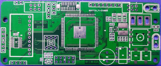
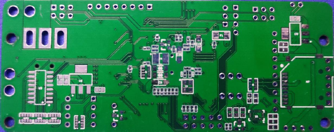
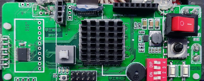
4.2. 1 power management module
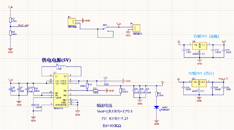
in this competition, the super capacitor bank is used to power the hardware system of the car model, and the TPS63070 chip is used to convert the electric energy of the super capacitor into 5V electric energy to power the main board. This chip has the advantages of high efficiency and simple peripheral circuit. At the same time, two AMS1117 chips are used to convert 5V voltage to 3.3V to supply power to the chip and module. The ship type switch is used as the main switch to control the opening and closing of the overall function of the vehicle model. The voltage information of the super capacitor bank is collected by using the voltage dividing resistance, so as to perceive the energy status of the collected capacitor bank.
4.2.2 MCU minimum system
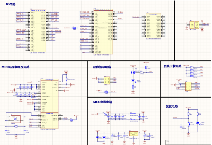
4.2. 2 human computer interaction module
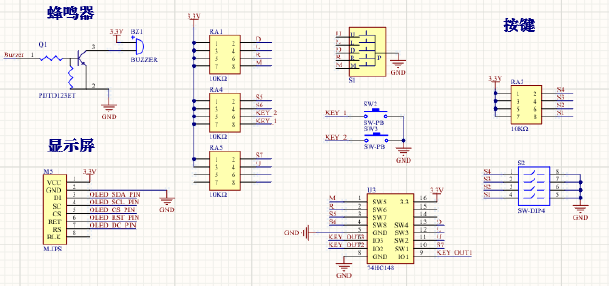
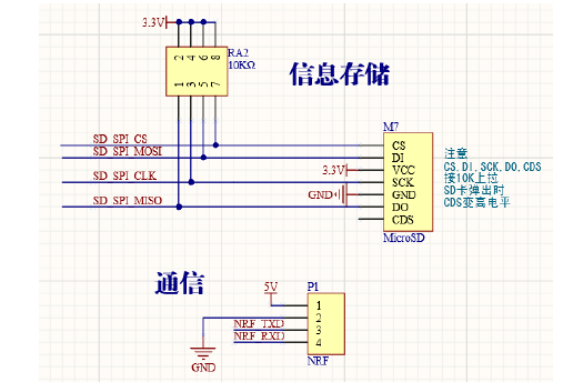
in the human-computer interaction part, an IPS screen is used to display information for convenient shunting. At the same time, a buzzer is also used to understand the status of the train when the train is running. In addition, a five way switch and a 4-bit dial switch are used to realize parameter adjustment. The principle is that when a switch is triggered, a low level will be generated at the corresponding port, and then the signal will be generated at the corresponding port of the single chip microcomputer through the eight wire three wire priority encoder 74HC148, which is detected by the single chip microcomputer and matched with the corresponding program to realize the specific function. The communication part adopts the NRF scheme. Finally, an SD card interface is designed to obtain the data collected by the camera.
4.2. 3 sensor module interface
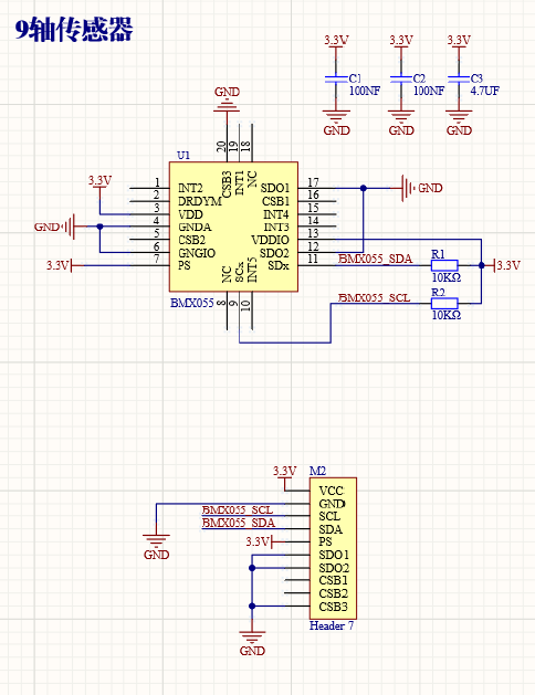
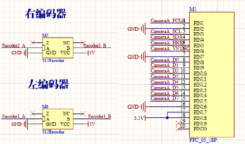
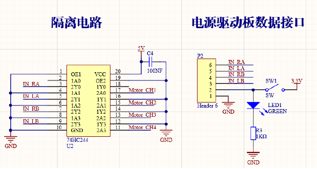
4.2. 4 motor module interface
4.3 design of power drive board
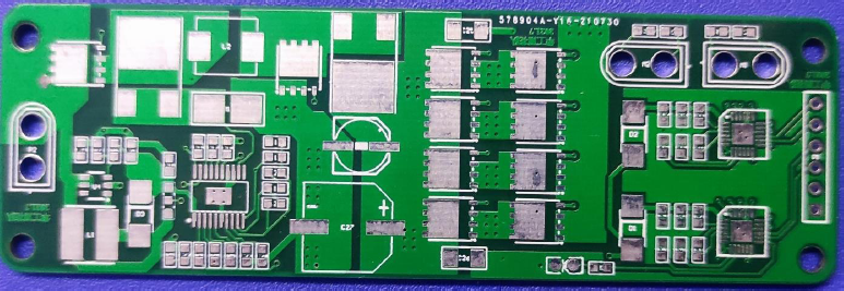
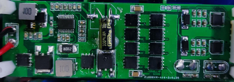
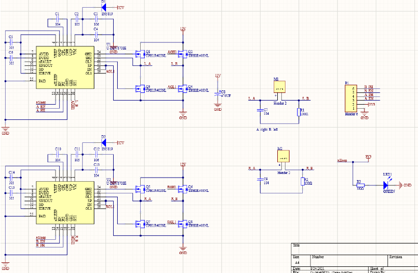
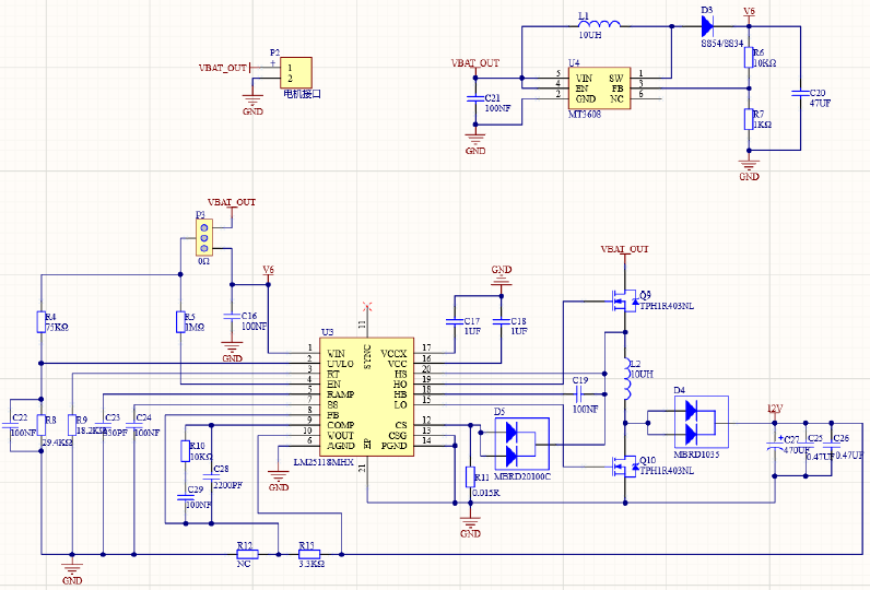
in terms of power drive board, it is divided into motor drive circuit and switching power supply circuit. The voltage stabilizing module adopts an LM25118MHX chip, and the required 12V voltage can be obtained after reasonable value of each component. The driving scheme uses DRV8701E chip to drive, that is, only two MOS tubes on one diagonal in the H bridge are connected through the control of the driving signal, so as to realize the forward rotation and reverse installation control of the motor, and cooperate with the PWM wave signal to realize the speed regulation of the motor.
4.4 design of charging board
the competition of energy saving group requires the contestants to use the wireless transmission module uniformly provided by the organizing committee to charge the super capacitor. The transmission frequency of the wireless transmission module used in this competition is 150kHz, and the transmission power is limited to 72W(24V3A) through brush firmware.
for the wireless charging part, there are two schemes: constant power charging and LCC topology circuit charging. The constant power scheme can keep the charging power of the load roughly at the set value by adjusting the circuit parameters, while the LCC topology circuit charging scheme can make the receiving end charge with constant current. Compared with previous wireless transmitting modules, the maximum power of wireless electromagnetic wave of energy-saving beacon group this year increases, and the transmitting system will not stop vibrating when exceeding the maximum power, and will continue to output at the maximum power. Therefore, our group finally adopts the "silly charging" scheme based on LCC topology circuit. However, it should be noted that due to the constant current characteristics of LCC compensation network, the Faraday capacitor charging voltage can be very high in theory. Therefore, it is necessary to immediately observe the voltage on the super capacitor in the process of acceptance. Once the threshold is exceeded, the model needs to leave the charging area quickly.
4.4. 1 wireless charging circuit
the wireless charging circuit is composed of LCC topology circuit and full bridge rectifier circuit. On the basis of full bridge rectifier, the charging current is constant through LCC compensation current.

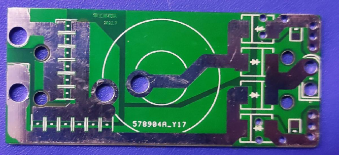
4.4. 2. Selection of charging circuit components
select appropriate charging circuit components according to various parameter requirements of wireless transmitting module:
the resonant capacitor of LCC topology circuit adopts C0G/NPO capacitor, which has the best temperature stability among class I ceramics, and the temperature characteristic is approximately 0.
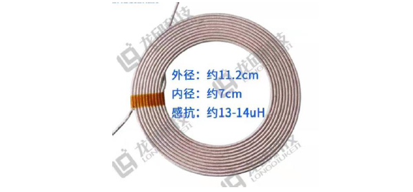
the receiving coil is an inductance coil wound with sand wrapped wire of Longqiu technology, and the inductance value is 13.4 Ω.
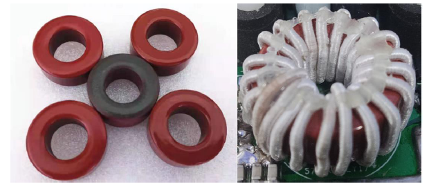
series wound inductor is formed by winding 21 turns of 200Litz wire on T106-2 magnetic core, and the inductance value is about 6.1 𝜇𝐻.
the SK1010C rectifier diode uses an average rectifier current of 10a and a DC reverse withstand voltage of 100V. Due to the LCC topology circuit, the output voltage is tens of volts. At the same time, in order to ensure the charging speed, the charging current can reach about 8A in the constant current stage. Therefore, the diode with withstand voltage and current of 100V and 10A is selected.
the super capacitor uses 5 Series 3V,50F Faraday capacitors. 980 Ω of energy can be stored from 0-14V.
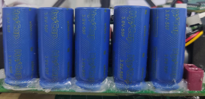
4.4. 3 Calculation and adjustment of charging circuit parameters
set the inductance value of receiving coil as 𝐿 0, the output inductance value as 𝐿, the parallel capacitance value as 𝐶, the series capacitance value as 𝐶, the LCC basic reactance 𝑋 0 = 𝑈 0, and the resonant frequency 𝑓 0 = 150 𝑘 𝐻 𝑧. Through the formula 𝐿 𝑠 = 𝑋 02 𝐿 𝐿 0 𝐶 𝑝 = 12 𝜋 𝑉 0 𝐶 𝐶 = 1 (2 𝜋 𝑓 0) 2 (𝐿 0 − 𝐿 𝑠)
according to the preliminary calculation, the output series inductance 𝐿 = 3.5 𝐷, the parallel capacitance value is 𝐶 = 320 𝐽, and the series capacitance value is 𝐶 𝐸 = 110 𝐽.
since the current value designed by this set of parameters is only 3A, assuming that the receiving efficiency is 50%, that is, the maximum receiving power is 36W, the super capacitor needs to be charged to 12V to reach the maximum power, and the charging speed is too slow. Therefore, it is necessary to increase the charging current. When the receiving coil remains unchanged, that is, reduce the basic reactance 𝑋 0. According to the above formula, reduce the output inductance value 𝐿 and increase the parallel capacitance value 𝐶. After the experiment, when the output inductance value decreases, that is, the number of turns of the wound coil decreases, but the charging current decreases greatly, which can not achieve the expected effect. It is speculated that the number of Litz wire turns may affect the upper limit of the charging current, so a balance is finally made, and the parallel capacitance value and output inductance value are increased at the same time, although they deviate from the resonance parameters, Sacrifice a certain charging efficiency, but in exchange for greater charging current, and finally improve the overall charging power.
after trial, the final charging circuit parameters are output series inductance 𝐿𝑠 = 6.1 𝐷𝐻, parallel capacitance = 469 𝐽𝐹, and series capacitance = 110 𝐽𝐹. The maximum current output is about 8A, and the maximum power reception can be achieved at about 5V. The average charging power of five series 50F supercapacitors is about 37W from 0V to 14V, and the charging efficiency is about 50%.
Chapter V intelligent vehicle control software design
5.1 software system framework
the control system consists of four modes, and each mode includes main cycle part and interrupt part, as shown in the figure below.
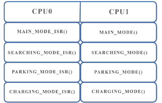
Infineon TC264 chip is a dual core architecture, including two parallel CPUs: CPU0 and CPU1. The main cycle part of each mode is executed in CPU1, and the interrupt part uses CPU0 resources to prevent resource preemption between interrupt and main cycle, so as to achieve real parallelism.
5.2 operation mode
1. The main mode is used to turn off the lights normally. It has three-level speed control, including start-up, acceleration and deceleration links. The start-up link prevents the model from hitting the blue lampshade, and the deceleration link prevents the model from rushing through the beacon light and increasing the distance, so it has the effect of "lighting up".
2. The light searching mode is used for light searching, and the steering is determined according to the prediction results.
3. The deceleration link of parking mode is similar to that of main mode. When it is a certain distance from the beacon light, it starts to decelerate until the light can not be seen.
4. The charging mode sets the speed to 0, so that the model can stably stop on the lamp for charging.
5.3 Association and switching between modes
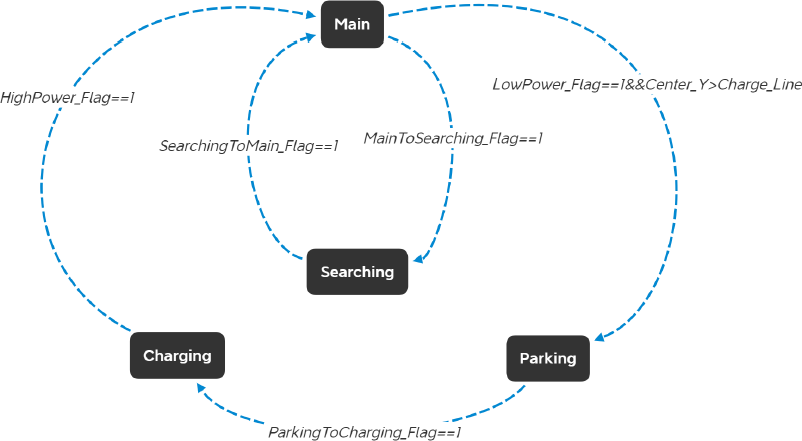
1. When the power is sufficient, the system mainly switches between the main mode and the light search mode. If you see the light, you will switch to the main mode, and if you can't see the light, you will switch to the light search mode.
2. When the power is insufficient and the model approaches the beacon lamp, switch to the parking charging mode, approach the beacon lamp at low speed until it stops stably on the lamp for charging.
3. Automatically switch back to the main mode after being fully charged.
5.4 image acquisition and processing
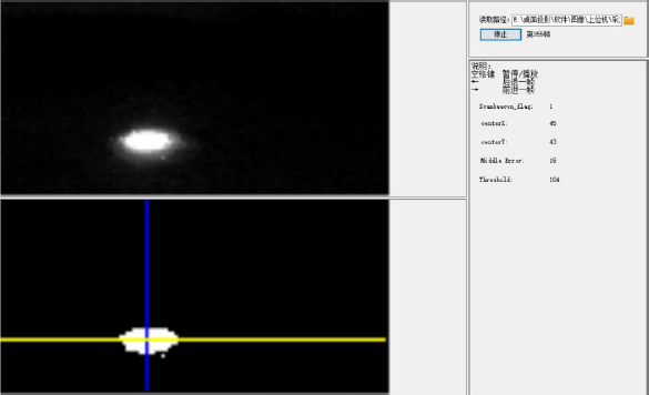
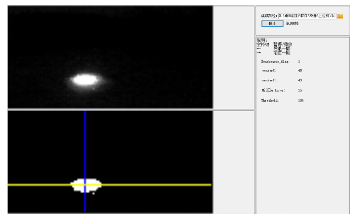
we use the general drilling air camera as the image acquisition sensor, use the Otsu method to convert the collected gray image into an appropriate binary image, and then conduct column scanning and row scanning to judge the number of white spots, so as to determine the coordinates centerX and centerY of the beacon lamp. The upper half is a gray image, and the lower half is a binary image.
5.5 steering prediction
in the process of light searching, the car model turns clockwise or counterclockwise. We find that specific steering can save time in different environments.
we use the BMX055 nine axis sensor for position calculation, which can calculate the yaw angle of the model relative to the initial position in real time, and record the current yaw angle every time we approach the beacon lamp. The steering of the current model is determined by the current yaw angle, the yaw angle before the last lamp and the last steering. After actual measurement, the accuracy of the prediction result is more than 98%.
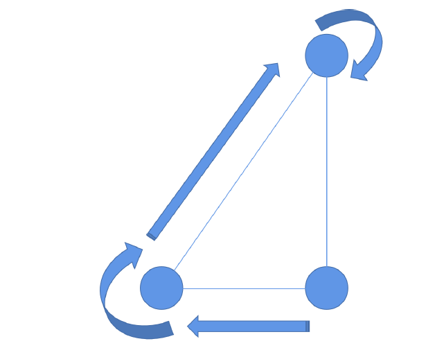
as shown in the above figure, according to the yaw angle at the two passing lights and the steering of the model on the last beacon light, we can calculate how many degrees the model has turned according to the last steering. If the difference exceeds a certain threshold, reverse the steering, otherwise continue the last steering.
5.6 motor PID control
PID control is the most widely used regulator control law in control engineering. It has been published for more than 70 years. It has become one of the main technologies of industrial control because of its simple structure, good stability, reliable operation and convenient adjustment. PID control is mainly composed of proportional, integral and differential parts. The PID control principle block diagram of unit feedback is shown in the figure below.

-
Basic introduction to the functions of PID parameters:
-
Proportional regulation: it reflects the deviation of the system in proportion. Once there is a deviation in the system, proportional regulation will immediately produce a regulation function to reduce the deviation. Large proportion can speed up the adjustment and reduce the error, but too large proportion will reduce the stability of the system and even cause the instability of the system.
-
Integral regulation function: it is to eliminate the steady-state error of the system and improve the error free degree. Because of the error, the integral adjustment is carried out until it reaches the zero error state, the integral adjustment stops, and the integral adjustment outputs a constant value. The strength of the integral action depends on the integral time constant. The smaller the integral action is, the stronger the integral action is. On the contrary, if it is large, the integral effect is weak. Adding integral regulation will reduce the stability of the system and slow down the dynamic response. Integral action is often combined with the other two regulation laws to form PI regulator or PID regulator.
-
Differential regulation function: the differential function reflects the change rate of system deviation signal, has predictability, can foresee the change trend of deviation, so it can produce advanced control function. Before the deviation is formed, the deviation has been eliminated by differential regulation function. Therefore, the dynamic performance of the system can be improved. Select the appropriate time in the differential
-
In this case, overshoot can be reduced and adjustment time can be reduced. Differential action can amplify noise interference, so too strong differential adjustment is unfavorable to the anti-interference performance of the system. In addition, the differential reaction is the rate of change, and when the input does not change, the differential action output is zero. Differential action cannot be used alone, but needs to be combined with other two regulation laws to form PD or PID controller.
-
General principles of PID commissioning:
the key to using PID control is to adjust three proportional coefficients, namely parameter setting. There are two kinds of PID tuning methods: one is theoretical calculation tuning method. It mainly determines the controller parameters through theoretical calculation according to the mathematical model of the system. Because the whole system of intelligent vehicle is a distributed parameter system with high electromechanical coupling, and the specific environment of the track should be considered, it is difficult to establish an accurate mathematical model of intelligent vehicle motion control, and we often modify the body mechanical structure, the model parameters change frequently and the operability is not strong; The second is the engineering setting method, which mainly depends on engineering experience and is directly carried out in the test of the control system. The method is simple. We have adopted this method. At the same time, we have experimented with several control methods that dynamically change PID parameters.
1. Increase the proportional gain when the output does not oscillate
2. Reduce the integration time constant when the output does not oscillate
3. When the output does not oscillate, increase the differential time constant
- General steps:
1) determine the proportional gain
when determining the proportional gain, first remove the integral term and differential term of PID, generally make the PID pure proportional regulation. The input is set to 60% - 70% of the maximum allowable value of the system, and the proportional gain is gradually increased from 0 until the system oscillates; In turn, the proportional gain decreases gradually from this time until the system oscillation disappears, record the proportional gain at this time, and set the proportional gain of PID to 60% 70% of the current value. Proportional gain debugging is completed.
2) determine the integration time constant
after the proportional gain is determined, set a large initial value of the integral time constant, and then gradually decrease until the system oscillates, and then turn around and gradually increase until the system oscillation disappears. Record the at this time, and set the integral time constant of PID to 150% ~ 180% of the current value. Integration time constant debugging is completed.
3) determine the integration time constant
generally, the integral time constant does not need to be set to 0. To set, the method is the same as that of determining sum, taking 30% without oscillation. No load and on load joint commissioning of the system, and then fine tune the PID parameters until they meet the requirements.
Chapter VI auxiliary description of development and debugging tools
6.1 development tools
aurixdevelopment studio is an integrated development environment integrating editing, compilation, debugging and simulation. It supports Infineon 32Bit multi-core chips, which are mainly used in automobile and industry. Infineon Technologies' TriCore architecture provides an industry-specific 32-bit microcontroller design optimized for automotive and industrial applications. The architecture provides an optimal balance between the real-time function of high-speed microcontroller, the original computing power of DSP and the performance and price of RISC load / storage architecture in a unified chipset. Aurixdevelopment Studio software development toolset is designed by Infineon experts and is regarded as the industry standard of TriCore architecture software. The toolset contains dedicated C/C + + compilers and assemblers for the complete TriCore family, as well as in the unified Eclipse ™ Multi core linker / locator and debugger in integrated development environment (IDE).
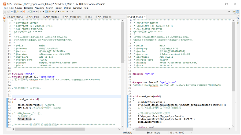
6.2 commissioning process
6.2. 1 image debugging host computer
to analyze the real-time information of the camera when the car model is driving, we must collect the real-time data of the gray camera during the car driving. We use the SD card to store the image data, and then use the computer image to debug the upper computer for analysis. It is a necessary tool for debugging, including software and hardware.
1) hardware
the SD card slot is designed on the hardware to connect the SPI interface of the single chip microcomputer. MCU receives the real-time data and writes it into SD card by SPI communication.
2) software
use C # to compile the upper computer interface under the drawing to analyze the camera information of SD card. At the same time, write the image processing program in the upper computer program to process the image information of SD card. You can carry out offline debugging on the computer to find the program defects in the sports car, so as to achieve the effect of debugging and improving the image processing program.
6.2. 2 parameter debugging host computer
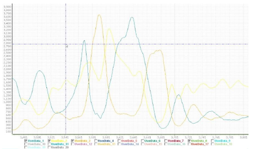
our team used the anonymous host computer of anonymous Kechuang to visualize the intelligent vehicle data, adjust the PID parameters and observe the vehicle model operation information through waveform analysis. Figure 8.3 shows the waveform interface of anonymous host computer.
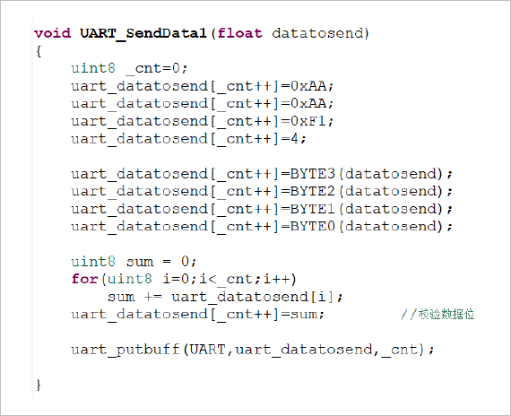
connecting the anonymous upper computer needs to process the data into the data frame of a specific protocol, so that the upper computer can decode normally and display the normal waveform. In this regard, we wrote a data transfer function call library in the underlying program, processed the data by protocol, and then sent it to the computer anonymous host computer by UART. The subroutine for sending one data is shown in the figure. The subroutine for sending multiple data is similar to it. Please refer to the source code.
Chapter VII main parameters of model vehicle
7.1 shape parameters of intelligent vehicle
- 230mm long, 200mm wide and 330mm high
7.2 number and type of sensors
- 1 total drill air gray camera
- 2 Motor encoders
- 9-axis sensor 1
7.3 track information detection accuracy and frequency
- Track information detection accuracy: 2mm, frequency: 50Hz
Chapter VIII conclusion
it's not easy to bump along the way.
in the last two days, I also witnessed many unsatisfactory endings of others. I think what I should do if I were in that position. I'm probably unwilling. But we are still sentimentally attached. No matter how worrying problems we encounter near the time, the outcome is still satisfactory. Even if there is still a little regret, we can be relieved. Looking back on this period of time, our efforts finally brought the results we expected.
life lies in experience. We always hope to do so, and we have been trying to practice this idea, constantly experience and understand, enrich our experience, broaden our thinking and horizons, and should not be lost in self denial and self satisfaction. Try your best to explore and accumulate, and find what you love for a long time.
smart cars give us many unique things, both material and spiritual, fame, wealth and growth. It has also taught us that when facing new opportunities and challenges, we should abandon many obsessions and prejudices, see a broader sky, see the real essence, experience many landscapes in the world, get new insights and develop continuously.
reference
[1] Cai Xujia, Liu Haigang, Chen Guancheng, Li Yongxiang, Zhuang Yue Research on design and control algorithm of camera intelligent car [J] Industrial control computer, 2018,31 (12): 98-101
[2] Yan Xun Jin PID regulation of NXP Cup National Smart car competition [J] Science and technology wind, 2020 (10): 263
[3] Zhuo Qing, Huang Kaisheng, Shao Beibei. Learn to make smart cars [M]. Beijing: Beijing University of Aeronautics and Astronautics Press, 2007
■ appendix
● CPU0 Code:
i
nt core0_main(void)
{
    disableInterrupts();//Forbidden energy interruption
 get_clk(); //To obtain the clock frequency, be sure to keep it

// MID_Buzzer_Init();
 //Total initialization
    Total_Init();

//***********Initialization function used for the test*******************************************

//    Test_Init_1();// Encoder motor initialization test and display on IPS
//    Test_Init_2();//IPS debugging interface test
//    Test_Init_3();// Timing measurement
//   Test_Init_4();// Camera test
//    Test_Init_5();// Basically can run
//   Test_Init_6();
//    Test_Init_7();// Attitude solution
//   Test_Init_8();//BMX055 gyroscope test
//    Test_Init_9();// Charging test
//    Test_Init_10();// Steering gear test
//    Test_Init_11();// Dual core communication - slave
//    Test_Init_12();// Dual core communication - host
//***************************************************************************

 enableInterrupts();//Enable interrupt

 while (TRUE)
 {
     if(Car_Mode!=Support_Mode)
     {
       APP_Buzzer_Task();
       MID_ANO_Send_Data4(UART_0, Encoder_L, Encoder_R,Encoder_Real,PWM_SPEED);
//       MID_ANO_Send_Data4(UART_0, PWM_Left_Uart, PWM_Right_Uart, PWM_SPEED,Encoder_Real);
//       MID_ANO_Send_Data4(UART_0, middle_error, PWM_Direction, Angel_z_Filter, PWM_Angle);
//       MID_ANO_Send_Data4(UART_0, Angel_z_Filter,middle_error,PWM_Angle,PWM_SPEED);
     }

//***********Test routines****************************************************

//     Test_1();// Encoder motor initialization test and display on IPS
//     Test_2();//IPS debugging interface test
//     Test_3();// Timing measurement
//     Test_4();// Camera test
//     Test_5();// Basically can run
//     Test_6();// Dual core test
//      Test_7();// Attitude solution
//     Test_8();//BMX055 gyroscope test
//     Test_9(); // Charging test
//     Test_10();// Steering gear test
//     Test_11();// Dual core test - slave
//      Test_12();// Dual core test - host

//*****************************************************************************

 }//End while

}//End main
● CPU1 Code:
void core1_main(void)
{
 disableInterrupts();
    IfxScuWdt_disableCpuWatchdog(IfxScuWdt_getCpuWatchdogPassword());
    //Users call various initialization functions here

 //Wait for all cores to initialize
 IfxCpu_emitEvent(&g_cpuSyncEvent);
 IfxCpu_waitEvent(&g_cpuSyncEvent, 0xFFFF);
    enableInterrupts();

    while (TRUE)
    {
  //The user writes the task code here
        switch(Car_Mode)
        {
            case Support_Mode: SUPPORT_MODE(); break;
            case Main_Mode: MAIN_MODE(); break;
            case Searching_Mode: SEARCHING_MODE(); break;
            case Parking_Mode: PARKING_MODE(); break;
            case Charging_Mode: CHARGING_MODE(); break;
        }

    }
}
● timing interrupt code:
#include "isr_config.h"
#include "isr.h"

uint32 Time=1;

uint32 AvoidBluePlate_Time = 1;
u8 AvoidBluePlate_Flag = 0;

uint32 Buffer_Time = 1;
u8 Buffer_Flag = 0;

u8 Charging_Time_Flag=0;
uint32 Charging_Time_Count;

u8 Delay_Flag = 0;
uint32 Delay_Time_Count;

//Example of PIT interrupt function
IFX_INTERRUPT(cc60_pit_ch0_isr, 0, CCU6_0_CH0_ISR_PRIORITY)
{
 //enableInterrupts();// Turn on interrupt nesting
 PIT_CLEAR_FLAG(CCU6_0, PIT_CH0);

 Time++;
    if(Time>20)
    {
        Time = 1;
    }

//Power detection delay
    if(Delay_Flag==0)
    {
        Delay_Time_Count++;
        if(Delay_Time_Count>2000)
        {
            Delay_Time_Count = 1;
            Delay_Flag = 1;
        }
    }

//Parking charging buffer
    if(Car_Mode==Main_Mode&&AvoidBluePlate_Flag==0)
    {
        AvoidBluePlate_Time++;
        if(AvoidBluePlate_Time>900)
        {
            AvoidBluePlate_Time = 1;
            AvoidBluePlate_Flag = 1;
        }
    }
    else
    {
        AvoidBluePlate_Time = 1;
    }

//Speed tertiary buffer
    if(Car_Mode==Main_Mode&&Buffer_Flag==0)
    {
        Buffer_Time++;
        if(Buffer_Time>500)
        {
            Buffer_Time = 1;
            Buffer_Flag = 1;
        }
    }
    else
    {
        Buffer_Time = 1;
    }

//    if(Time>5)
//    {
//        Time = 1;
//        MID_Encoder_Run();
//        MID_ANO_Send_Data4(UART_0, 0, 0, 0, Encoder_Real/1.477);
//    }

//    if(Charging_Time_Flag==0)
//    {
//        Charging_Time_Count++;
//        if(Charging_Time_Count>5000)
//        {
//
//            Charging_Time_Flag = 1;
//        }
//    }

// if(Time>20)
// {
//     Time=1;
////     gpio_set(P20_0,1);
////     Test_11();
////     gpio_set(P20_0,0);
// }
//********************************Mode selection*********************************************//
    switch(Car_Mode)
    {
        case Main_Mode: MAIN_MODE_ISR(); break;
        case Searching_Mode: SEARCHING_MODE_ISR(); break;
        case Parking_Mode: PARKING_MODE_ISR(); break;
        case Charging_Mode: CHARGING_MODE_ISR(); break;
        default:break;
    }
//************************Timed interrupt Ending*********************************//

}
● main loop thread code:
/**********************************************************************************
Program description: set of auxiliary functions as main function
Including: various sports car modes and auxiliary program packages
Supplement: None

**********************************************************************************/

#include <Mode/APP_Mode.h>

/****************************Flag bit variable area*************************************************/
u8 Car_Mode=0;
u8 Interrupt_Flag = 0;                    //Replace parameter flag bit
u8 LowPower_Flag = 0;
u8 HighPower_Flag = 0;
u8 Distance_Juge_Flag = 0;

int Approach_Line_Near;
int Approach_Line_Far;
int Approach_Line;
int Charge_Line;

uint32 HeadUp_Duty;
uint32 HeadDown_Duty;

float middle_error_count = 0; //Middle for rotation_ Error self increment

//=======================================================================================================
//                                    Debug function mode SUPPORT_MODE
//=======================================================================================================
void SUPPORT_MODE(void)
{
    Mode_Transition();//Mode switching buffer

    MID_Set_PWM(ATOM3_CH4_P11_9, 0);       //Left motor
    MID_Set_PWM(ATOM3_CH5_P11_10, 0);
    MID_Set_PWM(ATOM3_CH6_P11_11, 0 );     //Right motor
    MID_Set_PWM(ATOM3_CH7_P11_12, 0);

    if(mt9v03x_finish_flag)
    {
      APP_Image_Recognition();//Image processing thread

      MID_BMX055_Filter_Run();//Attitude angle + angular velocity acquisition
      MID_Encoder_Run();//Encoder data acquisition
      Power_Detect();//Power detection

      APP_GUI_TASK();//Show total threads
    }
}

//=======================================================================================================
//                          Main mode_ MODE
//=======================================================================================================
void MAIN_MODE(void)
{
    Mode_Transition();//Mode switching buffer

//Direction control
    if(mt9v03x_finish_flag)
    {
        APP_Image_Recognition();//Image processing thread
        CAM_Direction_Control();//PID calculation of camera outer ring
        Map_Detect();//Judge the rotation direction of the lamp this time (execute when the lamp is almost reached)
        Image_Detect(0);//Buffer from main mode to light seeking mode
    }

//Switching from main mode to light seeking mode
    if(MainToSearching_Flag)
    {
        MainToSearching_Flag = 0;
        Car_Mode = Searching_Mode;
    }

//Switching from main mode to parking mode
    if(LowPower_Flag==1&&Charging_Lock_Flag==0)
    {
        if(Center_Y>=Charge_Line&&Center_Y<=(Charge_Line+1)&&AvoidBluePlate_Flag==1)//Prevent sudden power failure in close proximity and jump into parking mode
        {
            Car_Mode = Parking_Mode;
        }
        else
        {
            Charging_Lock_Flag = 1;
        }
    }

    else if(Charging_Lock_Flag==1&&Center_Y>Charge_Line&&AvoidBluePlate_Flag==1)
    {
        Car_Mode = Parking_Mode;
    }

}

//=======================================================================================================
//                                            Searching mode_ MODE
//=======================================================================================================
void SEARCHING_MODE(void)
{
//Rotation task (direction ring)
    if(mt9v03x_finish_flag)
    {
        APP_Image_Recognition();//Image processing thread
        Rotation_Task();//Determine the rotation state according to the map recognition results
        CAM_Direction_Control();//PID calculation of camera outer ring
        Image_Detect(1);//Buffer from light seeking mode to main mode
    }

//Mode switching
    if(SearchingToMain_Flag==1)
    {
        SearchingToMain_Flag = 0;
        middle_error_count=0;
        Car_Mode = Main_Mode;
        AvoidBluePlate_Flag = 0;
        Buffer_Flag = 0;
    }
}

//=======================================================================================================
//                                            Parking mode PARKING_MODE
//=======================================================================================================
void PARKING_MODE(void)
{
//Direction control
    if(mt9v03x_finish_flag)
    {
        APP_Image_Recognition();//Image processing thread
        CAM_Direction_Control();//PID calculation of camera outer ring
        Image_Detect(2);//Buffer for mode switching
    }

//Mode switching
    if(ParkingToCharging_Flag==1)
    {
        ParkingToCharging_Flag = 0;
        Car_Mode = Charging_Mode;
    }
}

//=======================================================================================================
//                                            Charging mode CHARGING_MODE
//=======================================================================================================
void CHARGING_MODE(void)
{
    Mode_Transition();//Mode switching buffer

//Mode switching
    if(HighPower_Flag==1)
    {
        Car_Mode = Main_Mode;
        Charging_Lock_Flag = 0;
        AvoidBluePlate_Flag = 0;//Return to main mode enable count
        Buffer_Flag = 0;
        Halfway_Flag++;
        if(Halfway_Flag>2)
        {
            Halfway_Flag = 2;
        }

    }
}
● interrupt thread code:
/**********************************************************************************
Program description: set of auxiliary functions as isr function
Including: interrupt programs of various modes
Supplement: None
**********************************************************************************/

#include <Mode/APP_Mode_Isr.h>

//=======================================================================================================
//                                       Interrupt main mode_ MODE_ ISR
//=======================================================================================================
void MAIN_MODE_ISR(void)
{
//speed control
    if(Time%5==0)
    {
        if(Buffer_Flag==0)
        {
            Distance_Stable_Flag = 0;//Start ring enable
        }
        else if(Center_Y>Approach_Line)
        {
               Distance_Stable_Flag = 2;//Reduction ring enable
        }
        else
        {
            Distance_Stable_Flag = 1;//Accelerator ring enable
        }

//Determine the speed control status according to the identification results
        if(Distance_Stable_Flag==0)//Start loop control
        {
            Speed_Change(Start_V,5);//Starting speed
            PID_Para_Change(&PID_SPEED,Tag_V_Kp,Tag_V_Ki,0);
            Speed_Common_Control();
        }

        else if(Distance_Stable_Flag==2)//Reduction ring control
        {
            Speed_Change(Approach_V,10);//Deceleration speed
            PID_Para_Change(&PID_SPEED,Approach_V_Kp,Approach_V_Ki,0);
            Speed_Common_Control();
        }

        else if(Distance_Stable_Flag==1)//Acceleration ring control
        {
            Speed_Change(Tag_V,5);//Acceleration speed
            PID_Para_Change(&PID_SPEED,Tag_V_Kp,Tag_V_Ki,0);
            Speed_Common_Control();
        }

        PWM_Control();
    }

//Angle control
    if(Time%2==0)
    {
        MID_BMX055_Filter_Run();//Attitude solution
        CAM_Angle_Control();
        PWM_Control();
    }

//Energy detection
    if(Time%10==0)
    {
        Power_Detect();//Energy detection

    }
}

//=======================================================================================================
//                                        Interrupt lamp searching mode_ MODE_ ISR
//=======================================================================================================
void SEARCHING_MODE_ISR(void)
{
//speed control
    if(Time%5==0)
    {
        MID_Encoder_Run();//Encoder data acquisition and processing
        PWM_SPEED = Her_Speed;
        PWM_Search_Control();
    }

//Angle control
    if(Time%2==0)
    {
        MID_BMX055_Filter_Run();//Attitude solution
        CAM_Angle_Control();
        PWM_Search_Control();
    }
}

//=======================================================================================================
//                                         Interrupt parking mode_ MODE_ ISR
//=======================================================================================================
void PARKING_MODE_ISR(void)
{
//speed control
    if(Time%5==0)
    {
        Speed_Change(Charge_V,1);
        PID_Para_Change(&PID_SPEED,125,2,0);//Approach_V_Ki

        Speed_Common_Control();

        PWM_Control();
    }

//Angle control
    if(Time%2==0)
    {
        MID_BMX055_Filter_Run();//Attitude solution
        CAM_Angle_Control();
        PWM_Control();
    }

}

//=======================================================================================================
//                                          Interrupt charging mode CHARGING_MODE_ISR
//=======================================================================================================
void CHARGING_MODE_ISR(void)
{
//speed control
    if(Time%5==0)
    {
        Speed_Change(0,1);
        PID_Para_Change(&PID_SPEED,250,1,0);//125,2
        Speed_Common_Control();

        PWM_Control();
    }

//Angle control
    if(Time%2==0)
    {
        MID_BMX055_Filter_Run();//Attitude solution
        PWM_Angle = 0;
        PWM_Control();
    }

//Energy detection
    if(Time%10==0)
    {
        Power_Detect();//Energy detection
    }
}
● relevant chart links:
- Figure 3.1 overall appearance of vehicle model
- Figure 3.4 camera erection diagram
- Figure 3.5 BMX055 sensor
- Encoder installation drawing
- Installation of main control board
- Installation of power drive board
- Supercapacitor board installation
- Charging board installation
- Overall design renderings
- Body design renderings
- Actual installation drawing of universal wheel
- Effect drawing of universal wheel
- Actual installation drawing of motor and rear wheel
- Effect drawing of motor fixing
- Physical drawing of bare board (front)
- Physical drawing of bare board (reverse)
- Physical drawing of main board
- Figure 4.1 schematic diagram of power management module
- Schematic diagram of MCU minimum system
- Schematic diagram of human-computer interaction (1)
- Schematic diagram of human-computer interaction (2)
- Schematic diagram of motor module interface
- Bare board diagram of power drive board
- Physical drawing of power drive board
- Schematic diagram of motor drive circuit
- Schematic diagram of voltage stabilizing circuit of 12V switching power supply
- Schematic diagram of wireless charging circuit
- Physical drawing of wireless charging circuit board
- Commodity map of Longqiu technology receiving coil
- T106-2 magnetic ring (left) and wound inductance (right)
- Physical drawing of 5-String 3V,50F farad capacitor
- Program frame diagram
- Mode switching diagram
- Schematic diagram of position solution
- Control block diagram
- Development interface of aurixdevelopment studio
- Figure 8.3
- Waveform interface of anonymous host computer