1) Experimental platform: punctual atom alpha Linux development board
2) Platform purchase address: https://item.taobao.com/item.htm?id=603672744434
2) Full set of experimental source code + manual + video download address: http://www.openedv.com/thread-300792-1-1.html
3) Students interested in punctual atomic Linux can add group discussion: 935446741
4) pay attention to the official account of the dot atom and get updated information.

Chapter 29 LCD backlight adjustment experiment
Whether you use a monitor or a mobile phone, the screen backlight can be adjusted. By adjusting the backlight, you can control the brightness of the screen. When the outdoor sun is strong, you can see the screen by turning up the backlight. In dark places, you can turn down the backlight to prevent eye injury and save power. Three types of punctual atoms RGB LCD It also supports backlight adjustment. In this chapter, we will learn how to adjust it LCD Backlight.
29.1 introduction to LCD backlight adjustment
The three RGB LCD s of punctual atom have a backlight control pin. If you input a high level to the backlight control pin, the backlight will be lit, and if you input a low level, the backlight will be turned off. If we keep turning the backlight on and off, we won't feel the process when the speed is fast enough. This can be accomplished by PWM. The full name of PWM is Pulse Width Modulation, that is, Pulse Width Modulation. The PWM signal is shown in Figure 29.1 As shown in Figure 1:
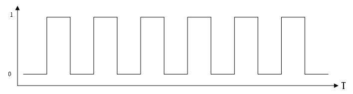
Figure 29.1 1 PWM signal
PWM signal has two key terms: frequency and duty cycle. Frequency is the switching speed. If a switch is counted as a cycle, then frequency is the number of switches in one second. Duty cycle is the ratio of high-level time to low-level time in a cycle. The longer the high-level time in a cycle, the greater the duty cycle. On the contrary, the smaller the duty cycle. The duty cycle is expressed in percent. If there are all low levels in a cycle, the duty cycle is 0%. If there are all high levels in a cycle, the duty cycle is 100%.
We input a PWM signal to the backlight pin of LCD, so we can adjust the brightness of LCD backlight by adjusting the duty cycle. Increasing the duty cycle will improve the backlight brightness, and reducing the duty cycle will reduce the backlight brightness. The focus is on the generation of PWM signal and the control of duty cycle. Fortunately, I.MX6U provides PWM peripherals, so we can configure PWM peripherals to generate PWM signal.
Open chapter 40 "Chapter 40 Pulse Width Modulation(PWM)" in I.MX6ULL reference manual. I.MX6U has 8 PWM signals. Each PWM includes a 16 bit counter and a 4 x 16 data FIFO. The PWM peripheral structure of I.MX6U is shown in Figure 29.1 As shown in Figure 2:

Figure 29.1 2. I.mx6u PWM structure block diagram
Figure 29.1 The functions of each part in 2 are as follows:
① This part is a selector used to select the clock source of PWM signal. There are three clock sources: ipg_clk,ipg_clk_highfreq and ipg_clk_32k.
② This is a 12 bit frequency divider, which can divide the clock source selected in ①.
③ This is the 16 bit counter register of PWM, which stores the count value of PWM.
④ This is the 16 bit cycle register of PWM, which is used to control the frequency of PWM.
⑤ This is the 16 bit sampling register of PWM, which is used to control the duty cycle of PWM.
⑥ This part is the interrupt signal of PWM. PWM provides the interrupt function. If the corresponding interrupt is enabled, the interrupt will be generated.
⑦ This part is the output IO corresponding to PWM, and the generated PWM signal will be output from the corresponding io. The LCD backlight control pin of I.MX6U-ALPHA development board is connected to gpio1 of I.MX6U_ On io8, GPIO1_IO8 can be reused as PWM1_OUT.
The frequency and duty cycle of PWM signal can be set by configuring corresponding registers. The 16 bit counter of PWM is an up counter, which will count from 0X0000 until the count value is equal to register PWMx_PWMPR(x=1~8) + 1, and then the counter will start counting again from 0X0000, and so on. So register PWMx_PWMPR can set the frequency of PWM.
In one cycle, when PWM starts counting from 0X0000, PWM pin outputs high level first (by default, low level can be output through configuration). The sampling value stored in the sampling FIFO will be compared with the counter value in each clock. When the sampling value is equal to the counter, the PWM pin will change to output low level (by default, the high level can also be output through configuration). The counter will continue counting until and the cycle register pwmx_ The values of pwmpr (x = 1 ~ 8) + 1 are equal, so a cycle is completed. Therefore, the sampling FIFO controls the duty cycle, and the value in the sampling FIFO comes from the sampling register PWMx_PWMSAR, therefore equivalent to PWMx_PWMSAR controls the duty cycle. So far, we know how to set the frequency and duty cycle of PWM signal.
After PWM is turned on, it will run according to the default value and generate PWM waveform, which is generally not the waveform we need. If this PWM waveform controls the equipment, it will cause the equipment to run incorrectly because it receives the wrong PWM signal. In serious cases, it may damage the equipment and even personal safety. Therefore, it is best to set pwmx before turning on PWM_ Pwmpr and PWMx_PWMSAR these two registers, that is, set the PWM frequency and duty cycle.
When we go to pwmx_ When the pwmsar register writes the sampling value, if the FIFO is not full, its value will be stored in the FIFO. If the FIFO is full, writing the sample value will result in register pwmx_ Bit FWE(bit6) of pwmsr is set to 1, indicating FIFO write error, and the value in FIFO will not change. FIFO can be written at any time, but read only when PWM is enabled. Register pwmx_ The bit FIFOAV(bit2:0) of SR records the number of data in the current FIFO. From sampling register pwmx_ When pwmsar reads data once, the data in FIFO will be reduced by one. Every time a cycle of PWM signal is generated, the data in FIFO will be reduced by one, which is equivalent to being used up. PWM has a FIFO null interrupt, which will be triggered when FIFO is empty. Data can be written to FIFO in this interrupt processing function.
That's all for the principle knowledge of PWM of I.MX6U. Next, let's take a look at several important registers of PWM. In this chapter, we use PWM1. First, let's take a look at register PWM1_PWMCR register. The register structure is shown in Figure 29.1 As shown in Figure 2:
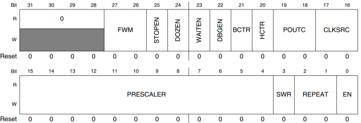
Figure 29.1 2 register PWM1_PWMCR register structure
Register pwm1_ The important bits used by pwmcr are as follows:
FWM(bit27:26): FIFO water level line, which is used to set the number of FIFO free positions, indicating that FIFO is empty. When set to 0, it means that FIFO is empty when the free position of FIFO is greater than or equal to 1; When set to 1, it means that FIFO is empty when the free position of FIFO is greater than or equal to 2; When it is set to 2, it means that FIFO is empty when the free position of FIFO is greater than or equal to 3; When it is set to 3, it means that FIFO is empty when the free position of FIFO is greater than or equal to 4.
Stop (bit25): this bit is used to set whether PWM works in stop mode. If it is 0, PWM continues to work in stop mode, and if it is 1, PWM is turned off in stop mode.
DOZEN(bit24): this bit is used to set whether PWM works in sleep mode. If it is 0, PWM continues to work in sleep mode, and if it is 1, PWM is turned off in sleep mode.
WAITEN(bit23): this bit is used to set whether PWM works in the waiting mode. If it is 0, PWM continues to work in the waiting mode, and if it is 1, PWM is turned off in the waiting mode.
DEGEN(bit22): this bit is used to set whether PWM works in debugging mode. If it is 0, PWM continues to work in debugging mode, and if it is 1, PWM is turned off in debugging mode.
BCTR(bit21): byte exchange control bit, which is used to control the byte order of 16 bit data entering FIFO. Byte exchange is not performed when it is 0, and byte exchange is performed when it is 1.
HCRT(bit20): half word switching control bit, which is used to determine which half word data transmitted from the 32-bit IP bus interface is written to the lower 16 bits of the sampling register.
POUTC(bit19:18): PWM output control bit, which is used to set PWM output mode. When it is 0, it means that PWM outputs high level first. When the counter value is equal to the sampling value, it outputs low level. On the contrary, when it is 1, when it is 2 or 3, the PWM signal is not output. In this chapter, we set it to 0, that is, when the counter value is equal to the sampling value, it will be changed to low level. In this way, the larger the sampling value, the longer the high-level time and the larger the duty cycle.
CLKSRC(bit17:16): PWM clock source selection. If it is 0, it will be closed; Select IPG for 1_ CLK is the clock source; Select IPG for 2_ clk_ Highfreq is the clock source; Select IPG for 3_ clk_ 32K is the clock source. In this chapter, we set it to 1, that is, select ipg_clk is the clock source of PWM, so the frequency of PWM clock source is 66MHz.
PRESCALER(bit15:4): frequency division value, which can be set to 04095, corresponding to 14096 frequency division.
SWR(bit3): software reset. Write 1 to this bit to reset PWM. This bit is self cleared. After the reset is completed, this bit will be automatically cleared.
REPEAT(bit2:1): repeat sampling setting. This bit is used to set how many times each data in FIFO can be used. 03 can be set to indicate that each data in FIFO can be used 14 times. In this chapter, we set it to 0, that is, each data in FIFO can only be used once.
EN(bit0): PWM enable bit, enable PWM when it is 1, and turn off PWM when it is 0.
Next, look at register PWM1_PWMIR register, which is the interrupt control register of PWM. The structure of this register is shown in Figure 29.1 As shown in Figure 3:
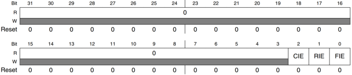
Figure 29.1 3 register PWM1_PWMIR structure
Register PWM1_PWMIR has only three bits. The meanings of these three bits are as follows:
CIE(bit2): compare interrupt enable bit, enable the compare interrupt when it is 1, and close the compare interrupt when it is 0.
RIE(bit1): flip interrupt enable bit. This interrupt will be generated when the counter value is equal to the sampling value and rolled back to 0X0000. When it is 1, the flip interrupt is enabled, and when it is 0, the flip interrupt is closed.
Fife (bit0): FIFO null interrupt. It is enabled when it is 1 and closed when it is 0.
Let's look at the status register PWM1_PWMSR, the register structure is shown in Figure 29.1 As shown in Figure 4:
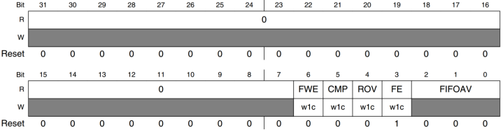
Figure 29.1 4 register PWM1_PWMSR structure
Register pwm1_ The meanings of pwmsr bits are as follows:
FWE(bit6): FIFO write error event. When it is 1, it indicates that a FIFO write error has occurred.
CMP(bit5): flag bit of FIFO comparison event. When it is 1, it indicates that FIFO comparison event occurs.
ROV(bit4): flip event flag bit. If it is 1, it indicates that the flip event occurs.
FE(bit3): FIFO null flag bit. When it is 1, it indicates that FIFO bit is null.
FIFOAV(bit2:1): this bit records the number of valid data in FIFO. The valid value is 04, indicating that there are 04 valid data in FIFO respectively.
Next is register PWM1_PWMPR register, which is the PWM cycle register, can be used to set the PWM frequency. The register structure is shown in Figure 29.1 As shown in Figure 5:

Figure 29.1 5 register PWM1_PWMPR register
From figure 29.1 5 it can be seen that register PWM1_PWMPR is only valid in the lower 16 bits. When the value of PWM counter is equal to PERIOD+1, it will restart counting from 0X0000 and start another cycle. The frequency calculation formula of PWM is as follows:
PWMO(Hz) = PCLK(Hz) / (PERIOD + 2)
PCLK is the clock frequency that finally enters PWM. If the frequency of PCLK is 1MHz, now we want to generate a PWM signal with frequency of 1KHz, then we can set PERIOD = 1000000 / 1000 – 2 = 998.
Finally, let's look at register PWM1_PWMSAR, a sampling register, is used to set the duty cycle. The register structure is shown in Figure 29.1 As shown in Figure 6:

Figure 29.1 6 register PWM1_PWMSAR structure
This register is also valid only for the lower 16 bits, which is the sampling value. Through this sampling value, the duty cycle can be adjusted. When the value of the counter is less than SAMPLE, the high level (or low level) is output. When the counter value is greater than or equal to SAMPLE, it is less than register PWM1_PWMPR outputs low level (or high level) during PERIO. Similarly, in the above example, if we want to set the duty cycle of PWM signal to 50%, we can set SAMPLE to (PERIOD + 2) / 2 = 1000 / 2=500.
Here are the registers related to PWM. For a detailed description of these registers, please refer to section 40.7 on page 2480 of I.MX6ULL reference manual. In this chapter, we use PWM1 of I.MX6U, and the output pin of PWM1 is GPIO1_IO8, configuration steps are as follows:
1. Configuration pin GPIO1_IO8
Configure gpio1_ The multiplexing function of io08 is multiplexed into PWM1_OUT signal line.
2. Initialize PWM1
Initialize PWM1 and configure the frequency and default duty cycle of the required PWM signal.
3. Set interrupt
Because the sampling value in FIFO will be less than one in each cycle, it is necessary to constantly write the sampling value to FIFO to prevent it from being empty. We can enable FIFO null interrupt, so that when FIFO is empty, the corresponding interrupt will be triggered, and then the sampling value will be written to FIFO in the interrupt processing function.
4. Enable PWM1
After configuring PWM1, it can be started.
29.2 hardware principle analysis
The resources used in this test are as follows:
① . indicator LED0.
② RGB, LCD interface.
③ , key KEY0
Refer to Chapter 24 for the hardware schematic diagram used in this experiment. At the beginning of this chapter, we set the backlight brightness PWM signal frequency of RGB LCD to 1KHz and the duty cycle to 10%, so the screen brightness is very low. Then press key KEY0 to gradually increase the duty cycle of PWM signal in steps of 10%. When it reaches 100%, press KEY0 again, and the PWM signal duty cycle returns to 10% and starts again. LED0 flashes continuously to indicate that the system is running.
29.3 preparation of experimental procedures
The routine path corresponding to this experiment is: development board CD - > 1, bare metal routine - > 20_ pwm_ lcdbacklight.
The experiment in this chapter is completed on the basis of the routine in the previous chapter. Change the project name to "backlight", then create a folder named "backlight" under the bsp folder, and then create a new bsp in bsp/backlight_ backlight. C and bsp_backlight.h these two documents. In bsp_ backlight. Enter the following in H:
Example code 29.3.1 bsp_backlight.h File code
1  #ifndef _BACKLIGHT_H
2  #define _BACKLIGHT_H
3  /***************************************************************
4  Copyright © zuozhongkai Co., Ltd. 1998-2019. All rights reserved.
5  File name: bsp_backlight.c
6  Author: Zuo Zhongkai
7  Version: V1.0 0
8  Description: LCD backlight PWM driver header file.
9  Others: None
10 Forum: www.openedv.com com
11 Log: first version v1 0 created by Zuo Zhongkai on January 22, 2019
12 ***************************************************************/
13 #include "imx6ul.h"
14
15 /* Backlight PWM structure */
16 struct backlight_dev_struc
17 {
18  	unsigned char pwm_duty;     /* Duty cycle    */
19 };
20
21 /* Function declaration */
22 void backlight_init(void);
23 void pwm1_enable(void);
24 void pwm1_setsample_value(unsigned int value);
25 void pwm1_setperiod_value(unsigned int value);
26 void pwm1_setduty(unsigned char duty);
27 void pwm1_irqhandler(void);
28
29 #endif
file bsp_backlight.h The content of the file is simple, and a backlight is defined on line 16 PWM Structure, the rest is the function declaration. In file bsp_backlight.c Enter the following in:
Example code 29.3 2 bsp_ backlight. C document code
/***************************************************************
Copyright © zuozhongkai Co., Ltd. 1998-2019. All rights reserved.
File name: bsp_backlight.c
 Author: Zuo Zhongkai
 Version: V1.0 0
 Description: LCD backlight PWM driver file.
Others: None
 Forum: www.openedv.com com
 Log: first version v1 0 created by Zuo Zhongkai on January 22, 2019
***************************************************************/
1   #include "bsp_backlight.h"
2   #include "bsp_int.h"
3   #include "stdio.h"
4
5   struct backlight_dev_struc backlight_dev; /* Backlight equipment */
6
7   /*
8    * @description	: pwm1 Interrupt handling function
9    * @param       	: nothing
10   * @return      	: nothing
11   */
12  void pwm1_irqhandler(void)
13  {
14      if(PWM1->PWMSR & (1 << 3))  		/* FIFO For air break 		*/
15      {
16          /* Writing the duty cycle information into FIFO is actually setting the duty cycle */
17          pwm1_setduty(backlight_dev.pwm_duty);
18          PWM1->PWMSR |= (1 << 3); 	/* Write 1 clear interrupt flag bit 	*/
19      }
20  }
21
22  /*
23   * @description 	: Initialize backlight PWM
24   * @param       	: nothing
25   * @return      	: nothing
26   */
27  void backlight_init(void)
28  {
29      unsigned char i = 0;
30
31      /* 1,Backlight PWM IO initialization, multiplexed to PWM1_OUT */
32      IOMUXC_SetPinMux(IOMUXC_GPIO1_IO08_PWM1_OUT, 0);
33      IOMUXC_SetPinConfig(IOMUXC_GPIO1_IO08_PWM1_OUT, 0XB090);
34
35      /* 2,Initialize PWM1
36       * Initialization register PWMCR
37       * bit[27:26]	: 01  When the free position in FIFO is greater than or equal to 2, the FIFO empty flag value bit
38       * bit[25]    	: 0  PWM inoperative in stop mode
39       * bit[24]    	: 0   PWM does not work in sleep mode
40       * bit[23]    	: 0   PWM inoperative in wait mode
41       * bit[22]    	: 0   PWM does not work in debug mode
42       * bit[21]    	: 0   Turn off byte switching
43       * bit[20]    	: 0   Turn off half word data exchange
44       * bit[19:18] 	: 00  PWM The output pin outputs a high level when the counter counts again
45       *                     After the counter count value reaches the comparison value, the low level is output
46       * bit[17:16]	: 01  PWM Clock source selection IPG CLK = 66MHz
47       * bit[15:4]  	: 65  The frequency division coefficient is 65 + 1 = 66, PWM clock source = 66MHZ/66=1MHz
48       * bit[3]     	: 0   PWM No reset
49       * bit[2:1]   	: 00  FIFO The sample data in can only be used once each.
50       * bit[0]     	: 0   Turn off PWM before enabling it
51       */
52      PWM1->PWMCR = 0;    /* The register is cleared first */
53      PWM1->PWMCR |= (1 << 26) | (1 << 16) | (65 << 4);
54
55      /* If the PWM cycle is set to 1000, the PWM frequency is 1M/1000 = 1KHz. */
56      pwm1_setperiod_value(1000);
57
58      /* Set the duty cycle. The default duty cycle is 50%. Write it four times because there are four FIFO s */
59      backlight_dev.pwm_duty = 50;
60      for(i = 0; i < 4; i++)
61      {
62          pwm1_setduty(backlight_dev.pwm_duty);
63      }
64
65      /* Enable FIFO null interrupt and set bit0 of PWMIR register to 1 */
66      PWM1->PWMIR |= 1 << 0;
67      system_register_irqhandler(PWM1_IRQn, 	/* Register interrupt service function 		*/
(system_irq_handler_t)pwm1_irqhandler, NULL);
68      GIC_EnableIRQ(PWM1_IRQn);   				/* Enable the corresponding interrupt in GIC */
69      PWM1->PWMSR = 0;            				/* PWM Reset interrupt status register */
70      pwm1_enable();              				/* Enable PWM1 			*/
71  }
72
73  /*
74   * @description 	: Enable PWM
75   * @param       	: nothing
76   * @return      	: nothing
77   */
78  void pwm1_enable(void)
79  {
80      PWM1->PWMCR |= 1 << 0;
81  }
82
83  /*
84   * @description	: Set the Sample register, and the Sample data will be written to the FIFO
85   *                    Sample Register is equivalent to the comparison register, if the poitc in PWMCR
86   *                    When set to 00. When the count value in PWM counter is less than Sample
87   *                    It will output high level and output bottom power when the PWM counter value is greater than Sample
88   *                    Flat, so you can set the duty cycle by setting the Sample register.
89   * @param -  value: Register value, range 0 ~ 0xfff
90   * @return         : nothing
91   */
92  void pwm1_setsample_value(unsigned int value)
93  {
94      PWM1->PWMSAR = (value & 0XFFFF);
95  }
96
97  /*
98   * @description	: Setting the PWM cycle is to set the register PWMPR. The PWM cycle formula is as follows
99   *             	PWM_FRE = PWM_CLK / (PERIOD + 2), For example, current PWM_CLK=1MHz
100  *              To generate 1KHz PWM, PERIOD = 1000000/1K - 2 = 998
101  * @param -  value	: Cycle value, range 0 ~ 0xfff
102  * @return          	: nothing
103  */
104 void pwm1_setperiod_value(unsigned int value)
105 {
106     unsigned int regvalue = 0;
107
108     if(value < 2)
109         regvalue = 2;
110     else
111         regvalue = value - 2;
112     PWM1->PWMPR = (regvalue & 0XFFFF);
113 }
114
115 /*
116  * @description     	: Set PWM duty cycle
117  * @param -  value  	: Duty cycle 0 ~ 100, corresponding to 0% ~ 100%
118  * @return          	: nothing
119  */
120 void pwm1_setduty(unsigned char duty)
121 {
122     unsigned short preiod;
123     unsigned short sample;
124
125     backlight_dev.pwm_duty = duty;
126     preiod = PWM1->PWMPR + 2;
127     sample = preiod * backlight_dev.pwm_duty / 100;
128     pwm1_setsample_value(sample);
129 }
file bsp_blacklight.c There are six functions. The first is the function pwm1_irqhandler,This is PWM1 Interrupt handler for. Needs to be handled in this function FIFO Air break, when FIFO After the air break occurs, it is necessary to send data to the sampling register PWM1_PWMSAR Write the sampling data, that is, the duty cycle, and finally clear the corresponding interrupt flag bit. The second function is backlight_init,This is the backlight initialization function, in which the backlight pin will be initialized GPIO1_IO08,Reuse it as PWM1_OUT. This function is then initialized PWM1,Set to	Generated PWM Signal frequency and default duty cycle, then enable FIFO Air interrupt, register the corresponding interrupt processing function, and finally enable PWM1. The third function is pwm1_enable,For enabling PWM1. The fourth function is pwm1_setsample_value,Used to set the sampling value, that is, the register PWM1_PWMSAR Value of. The fifth function is pwm1_setperiod_value,Used to set PWM The frequency of the signal. The sixth function is pwm1_setduty,Used to set PWM This function has only one parameter duty,That is, the duty ratio, in%,The internal function calculates the register based on the percentage value PWM1_PWMSAR The value that should be set.
Finally in main.c Enter the following in the file:
Example code 29.3 3 main. C document code
/**************************************************************
Copyright © zuozhongkai Co., Ltd. 1998-2019. All rights reserved.
File name: main c
 Author: Zuo Zhongkai
 Version: V1.0 0
 Description: bare metal experiment of I.MX6U development board 21 backlight PWM experiment
 Others: the backlight can be adjusted when we use the mobile phone. The same I.MX6U-ALPHA
           The LCD backlight of the development board can also be adjusted. The LCD backlight is equivalent to an LED lamp.
           LED The light on and off can be controlled by PWM. In this experiment, we'll learn how to do it
           The backlight of LCD is controlled by PWM.
Forum: www.openedv.com com
 Log: first version v1 0 created by Zuo Zhongkai on January 21, 2019
**************************************************************/
1  #include "bsp_clk.h"
2  #include "bsp_delay.h"
3  #include "bsp_led.h"
4  #include "bsp_beep.h"
5  #include "bsp_key.h"
6  #include "bsp_int.h"
7  #include "bsp_uart.h"
8  #include "bsp_lcd.h"
9  #include "bsp_lcdapi.h"
10 #include "bsp_rtc.h"
11 #include "bsp_backlight.h"
12 #include "stdio.h"
13
14 /*
15  * @description	: main function
16  * @param        	: nothing
17  * @return       	: nothing
18  */
19 int main(void)
20 {
21  	unsigned char keyvalue = 0;
22  	unsigned char i = 0;
23  	unsigned char state = OFF;
24  	unsigned char duty = 0;
25
26  	int_init();          		/* Initialization interrupt (must be called first!)	*/
27  	imx6u_clkinit();         	/* Initialize system clock              	*/
28  	delay_init();             	/* Initialization delay                  	*/
29  	clk_enable();            	/* Enable all clocks              	*/
30  	led_init();               	/* Initialize led                   	*/
31  	beep_init();              	/* Initialize beep                  	*/
32  	uart_init();              	/* Initialize serial port, baud rate 115200 	*/
33  	lcd_init();               	/* Initialize LCD                   	*/
34 	 	backlight_init();       	/* Initialize backlight PWM               	*/
35
36  	tftlcd_dev.forecolor = LCD_RED;
37  	lcd_show_string(50, 10, 400, 24, 24,
(char*)"ALPHA-IMX6U BACKLIGHT PWM TEST");
38  	lcd_show_string(50, 40, 400, 24, 24, (char*)"PWM Duty:   %");
39  	tftlcd_dev.forecolor = LCD_BLUE;
40
41  	/* Set default duty cycle 10% */
42  	duty = 10;
43  	lcd_shownum(158, 40, duty, 3, 24);
44  	pwm1_setduty(duty);
45
46 	 	while(1)
47  	{
48      	keyvalue = key_getvalue();
49      	if(keyvalue == KEY0_VALUE)
50      	{
51         	 	duty += 10;      		/* Duty cycle plus 10% 	*/
52          		if(duty > 100)   		/* If the duty cycle exceeds 100%, start again at 10% */
53              		duty = 10;
54          		lcd_shownum(158, 40, duty, 3, 24);
55          		pwm1_setduty(duty);	/* Set duty cycle 	*/
56     		}
57
58      	delayms(10);
59      	i++;
60      	if(i == 50)
61      	{
62          		i = 0;
63          		state = !state;
64          		led_switch(LED0,state);
65      	}
66  	}
67  	return 0;
68 }
Line 34 calls the function backlight_init Initialize screen backlight PWM. Line 44 set backlight PWM The default duty cycle is 10%. stay main Function, if KEY0 If you press it, it will PWM The duty cycle of the signal increases by 10%,When the duty cycle exceeds 100%Return to 10 when%,restart. in general, main.c The content is still very simple.
29.4 compilation, download and verification
29.4. 1 Write Makefile and link script
Modify the TARGET in the Makefile to backlight, and then add "bsp/rtc" in incdir and SRCDIRS. The modified Makefile is as follows:
Example code 29.4 1 makefile code
1  CROSS_COMPILE 	?= arm-linux-gnueabihf-
2  TARGET          	?= backlight
3
4  /* Omit other codes */
5
6  INCDIRS      	:=	imx6ul \
7                  		stdio/include \
8                  		bsp/clk \
9                  		bsp/led \
10                 		bsp/delay  \
11                 		bsp/beep \
12                 		bsp/gpio \
13                 		bsp/key \
14                 		bsp/exit \
15                 		bsp/int \
16                 		bsp/epittimer \
17                 		bsp/keyfilter \
18                 		bsp/uart \
19                 		bsp/lcd \
20                 		bsp/rtc \
21                 		bsp/i2c \
22                 		bsp/ap3216c \
23                 		bsp/spi \
24                 		bsp/icm20608 \
25                 		bsp/touchscreen \
26                		bsp/backlight
27
28 SRCDIRS         := 	project \
29                 		stdio/lib \
30                 		bsp/clk \
31                 		bsp/led \
32                 		bsp/delay \
33                		bsp/beep \
34                 		bsp/gpio \
35                 		bsp/key \
36                 		bsp/exit \
37                 		bsp/int \
38                 		bsp/epittimer \
39                 		bsp/keyfilter \
40                 		bsp/uart \
41                 		bsp/lcd \
42                 		bsp/rtc \
43                 		bsp/i2c \
44                 		bsp/ap3216c \
45                 		bsp/spi \
46                 		bsp/icm20608 \
47                 		bsp/touchscreen \
48                 		bsp/backlight
49
50 /* Omit other codes */
51
52 clean:
53  rm -rf $(TARGET).elf $(TARGET).dis $(TARGET).bin $(COBJS) $(SOBJS)
In line 2, change the variable TARGET to "backlight", that is, the TARGET name is "backlight".
Line 26 add the backlight PWM driver header file (. h) path to the variable INCDIRS.
Line 48 add the backlight PWM driver file (. c) path to the variable SRCDIRS.
The linked script remains unchanged.
29.4. 2 compile and download
Use the Make command to compile the code. After the compilation is successful, use the software imxdownload to compile the completed backlight Download the bin file to the SD card. The command is as follows:
chmod 777 imxdownload / / allow imxdownload to execute once
./ imxdownload backlight.bin /dev/sdd / / burn to the SD card, not to / dev/sda or sda1!
After successful burning, insert the SD card into the SD card slot of the development board, and then reset the development board. The default backlight PWM is 10%, and the PWM signal waveform is shown in Figure 29.4 As shown in 2.1:
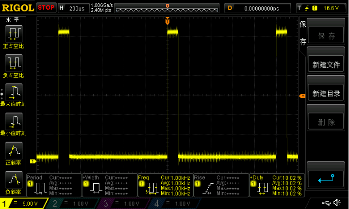
Figure 29.4 2.1 10% duty cycle PWM signal
From figure 29.4 2.1 it can be seen that the frequency of backlight PWM signal is 1.00KHz and the duty cycle is 10.02%, which is consistent with the configuration in our code. At this time, the screen display of LCD is shown in Figure 29.4 As shown in 2.2:

Figure 29.4 2.2 10% duty cycle screen brightness
Figure 29.4 2.2 is the LCD screen display with PWM duty cycle of 10%. It can be seen that the brightness of the screen is very low, and even the reflection of the photographer on the screen can be seen. Due to the reason of taking photos, the actual brightness may be slightly different from the actual situation.
We adjust the duty cycle of PWM to 90%. At this time, the LCD screen brightness will be very bright, as shown in Figure 29.4 As shown in 2.3:
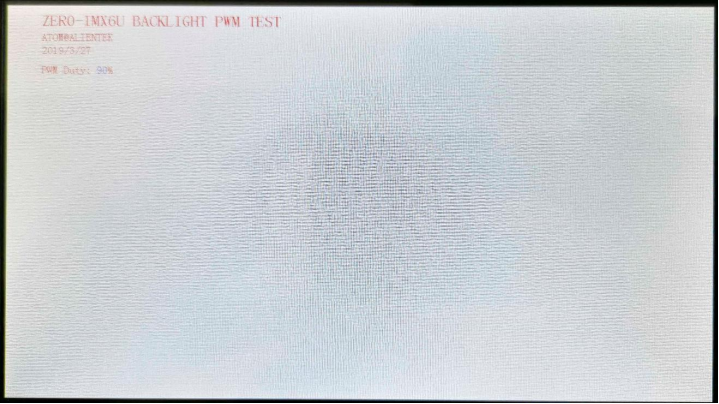
Figure 29.4 2.3 90% duty cycle screen brightness
Figure 29.4 2.3 screen brightness compared to figure 29.4 2.2 it is much higher. This is the principle of LCD backlight adjustment. It is completed by PWM waveform. Brightness adjustment can be completed by adjusting the duty cycle.
So far, all bare metal routines of I.MX6U-ALPHA development board have been completed. Through these dozens of bare metal routines, we have a basic understanding of the peripherals of I.MX6UL/ULL chip, which has laid a solid foundation for us to learn about Uboot and Linux driver in the future.