1, L298N drive introduction
Introduction and selection of driving part https://blog.csdn.net/weixin_46758622/article/details/115804098?ops_request_misc=%257B%2522request%255Fid%2522%253A%2522162918592516780261966328%2522%252C%2522scm%2522%253A%252220140713.130102334.pc%255Fblog.%2522%257D&request_id=162918592516780261966328&biz_id=0&utm_medium=distribute.pc_search_result.none -task-blog-2blogfirst_ rank_ v2~times_ rank-18-115804098. pc_ v2_ rank_ blog_ default&utm_ term=%E7%9B%B4%E6%B5%81%E5%87%8F%E9%80%9F%E7%94%B5%E6%9C%BA+hal&spm=1018.2226. three thousand and one point four four five zero
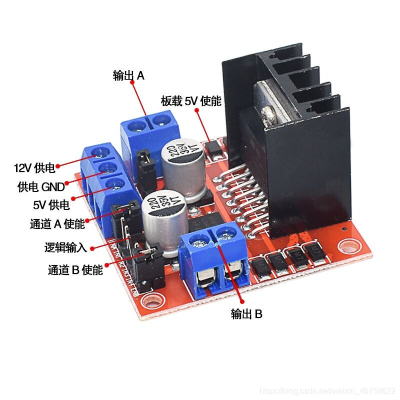
Output A (OUT1 and OUT2): the sequence does not matter. After connection, the forward and reverse can be determined according to IN1,IN2 or IN3,IN4
12V power supply and power supply GND: the 12V power supply interface is connected to the positive pole and negative pole of 12V battery. At the same time, it must be grounded with the single chip microcomputer. Try not to be higher than 16V or lower than 8V. If it is too high or too low, the chip may be burned.
5V power supply: since the L298N motor drive module has its own voltage stabilizing function, it can supply 5V voltage. In the future smart car project, this can be selected for the power supply of single chip microcomputer.
Channel A enable (EN1): the enable here can be compared with the GPIO port and clock configuration of STM32, which means to enable it. This enable interface is used to control the PWM input, that is, if you just want to make the motor rotate, you can ignore EN1 and cover it with that hat, it will be connected to 5v, that is, it will not be enabled. If you want to turn it later Use PWM to control, then pull out the hat and connect the EN pin to the PWM output port of the single chip microcomputer.
MCU IO port control input (IN1, IN2): these two pins are connected to two GPIO ports of STM32. By giving high and low levels, the forward and reverse rotation of the motor can be realized.
Therefore, the remaining IN3, IN4, EN2, OUT3 and OUT4 are the same.
If the power supply exceeds 12v, pull out the jumper cap, and then input 5v voltage at 5v.
If the power supply is less than 12v, plug in the jumper cap and 5v as the output terminal.
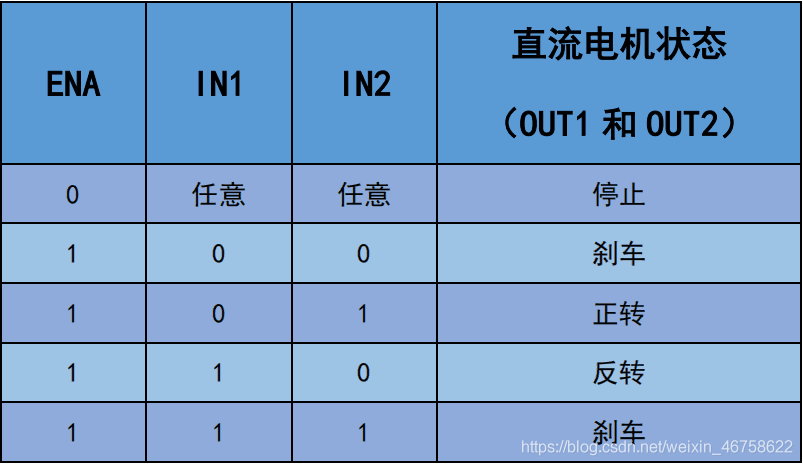
ENA and ENB are equivalent to switches. Inserting the jumper cap is equivalent to opening the switch and enabling two ports
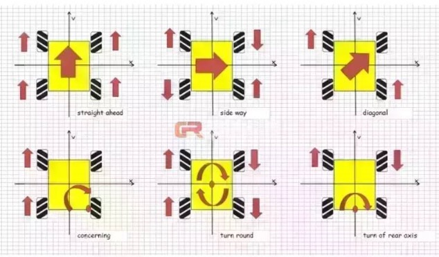
2, Characteristics and motion of mcnamu wheel
This paper does not make a detailed analysis, but only lists the motion states under different conditions. Due to the structural particularity of mcnamu wheel, it can achieve the special state of left-right translation.
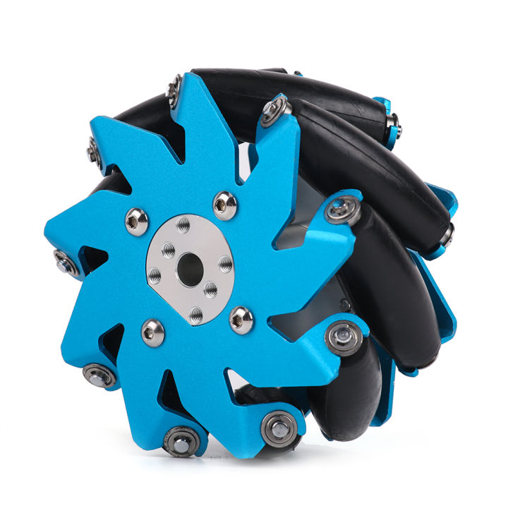
Below is a picture of a mcnamu wheel
When installing it on the trolley, pay attention to the distribution of wheels
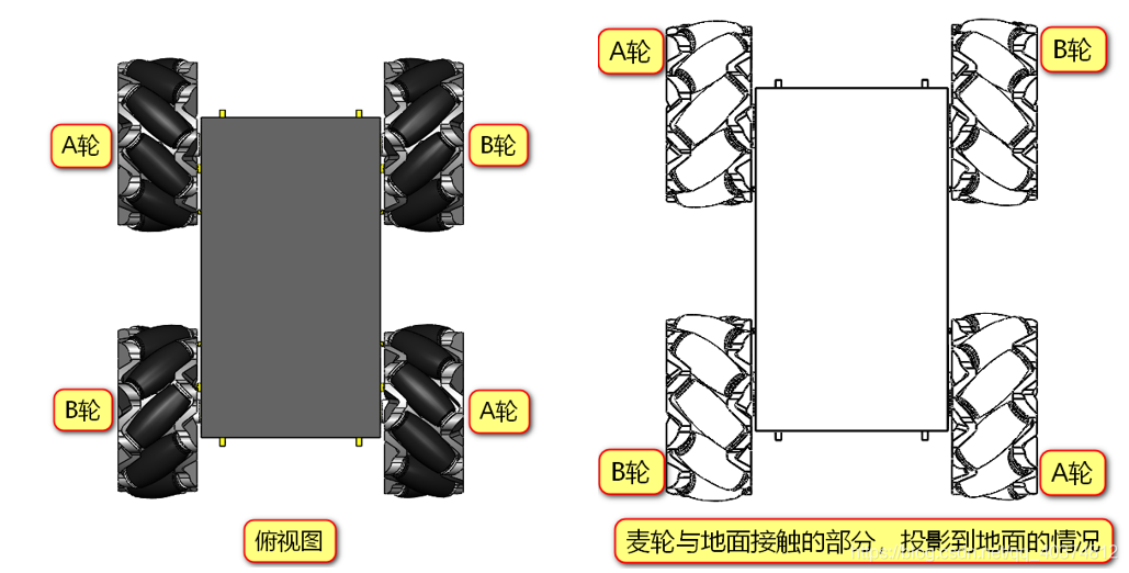
Presenting type O or X is considered to be the correct installation
The following is the final movement form of the trolley under different wheel states
3, CubeMx configuration
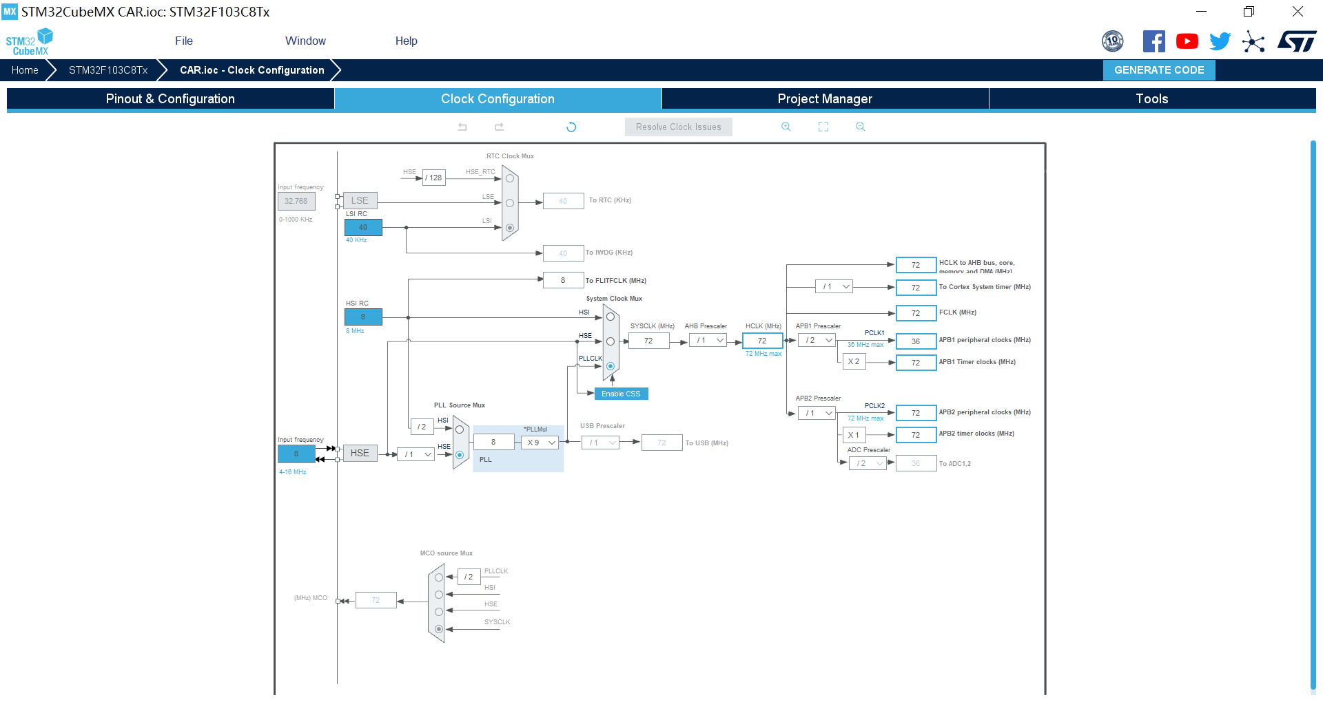
1.RCC
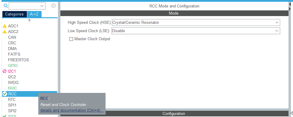
After setting, remember to adjust the clock tree F103 to 72Hz
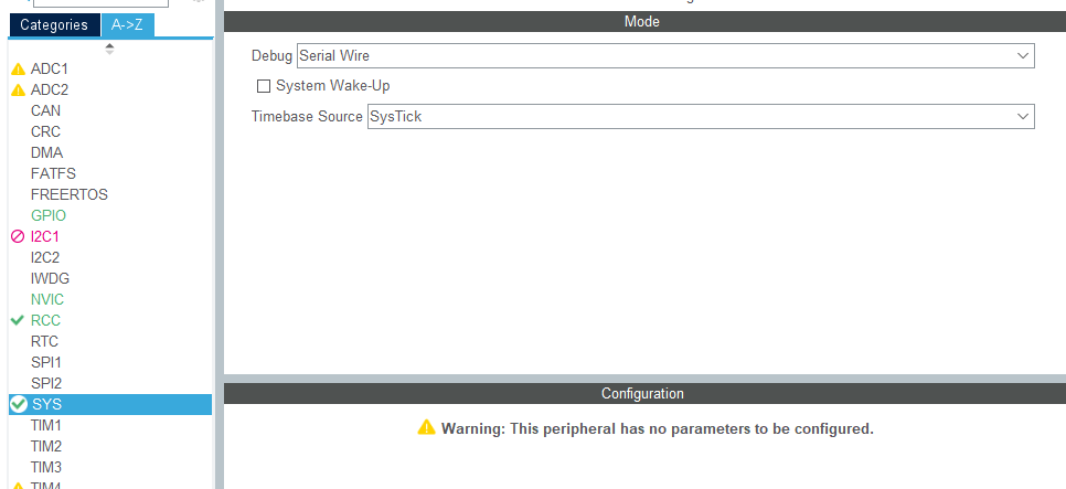
2.SYS
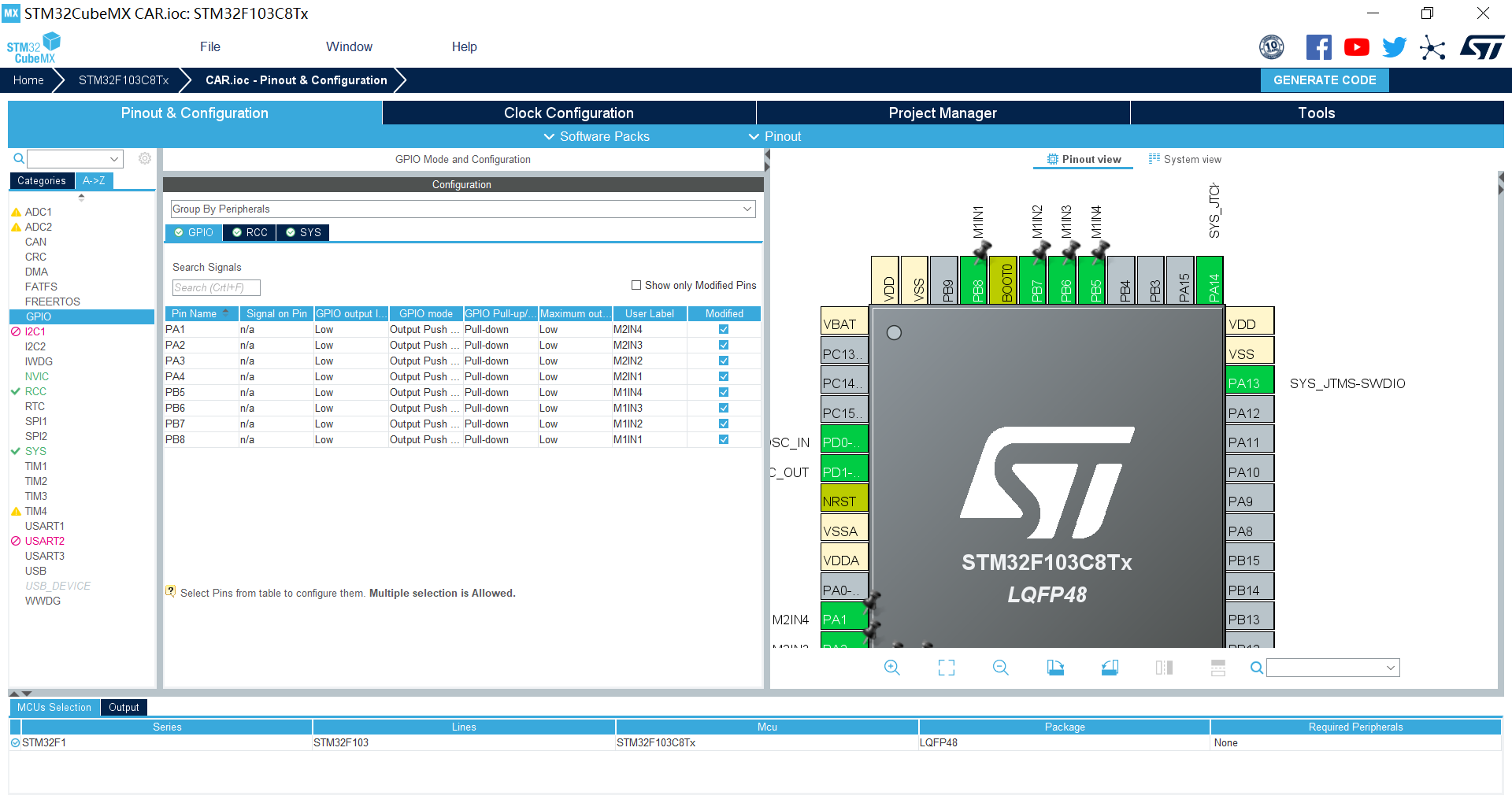
3.GPIO
GPIO is configured as follows
generate code
4, Code
According to the L298N principle described above, if you want to drive the motor with L298N, you only need to raise and lower the corresponding pin voltage at the corresponding time.
main.h
/* USER CODE BEGIN Private defines */

#define M1IN1_0 HAL_GPIO_WritePin(M1IN1_GPIO_Port,M1IN1_Pin,GPIO_PIN_RESET)
#define M1IN1_1 HAL_GPIO_WritePin(M1IN1_GPIO_Port,M1IN1_Pin,GPIO_PIN_SET)
#define M1IN2_0 HAL_GPIO_WritePin(M1IN2_GPIO_Port,M1IN2_Pin,GPIO_PIN_RESET)
#define M1IN2_1 HAL_GPIO_WritePin(M1IN2_GPIO_Port,M1IN2_Pin,GPIO_PIN_SET)
#define M1IN3_0 HAL_GPIO_WritePin(M1IN3_GPIO_Port,M1IN3_Pin,GPIO_PIN_RESET)
#define M1IN3_1 HAL_GPIO_WritePin(M1IN3_GPIO_Port,M1IN3_Pin,GPIO_PIN_SET)
#define M1IN4_0 HAL_GPIO_WritePin(M1IN4_GPIO_Port,M1IN4_Pin,GPIO_PIN_RESET)
#define M1IN4_1 HAL_GPIO_WritePin(M1IN4_GPIO_Port,M1IN4_Pin,GPIO_PIN_SET)

#define M2IN1_0 HAL_GPIO_WritePin(M2IN1_GPIO_Port,M2IN1_Pin,GPIO_PIN_RESET)
#define M2IN1_1 HAL_GPIO_WritePin(M2IN1_GPIO_Port,M2IN1_Pin,GPIO_PIN_SET)
#define M2IN2_0 HAL_GPIO_WritePin(M2IN2_GPIO_Port,M2IN2_Pin,GPIO_PIN_RESET)
#define M2IN2_1 HAL_GPIO_WritePin(M2IN2_GPIO_Port,M2IN2_Pin,GPIO_PIN_SET)
#define M2IN3_0 HAL_GPIO_WritePin(M2IN3_GPIO_Port,M2IN3_Pin,GPIO_PIN_RESET)
#define M2IN3_1 HAL_GPIO_WritePin(M2IN3_GPIO_Port,M2IN3_Pin,GPIO_PIN_SET)
#define M2IN4_0 HAL_GPIO_WritePin(M2IN4_GPIO_Port,M2IN4_Pin,GPIO_PIN_RESET)
#define M2IN4_1 HAL_GPIO_WritePin(M2IN4_GPIO_Port,M2IN4_Pin,GPIO_PIN_SET)
/* USER CODE END Private defines */
main.c
  while (1)
  {
    /* USER CODE END WHILE */

    /* USER CODE BEGIN 3 */

		HAL_Delay(100);
		forward();
		HAL_Delay(5000);
		backward();
		HAL_Delay(5000);
		shift_left();
		HAL_Delay(5000);
		shift_right();
		HAL_Delay(5000);
		turn_left();
		HAL_Delay(5000);
		turn_right();
		HAL_Delay(5000);
		Reset();
  }
  /* USER CODE END 3 */
Only the simplest forward and backward, left shift right shift left turn right turn, if there is any error, please correct it.