1) Experimental platform: punctual atom alpha Linux development board
2) Platform purchase address: https://item.taobao.com/item.htm?id=603672744434
2) Full set of experimental source code + manual + video download address: http://www.openedv.com/thread-300792-1-1.html
3) Students interested in punctual atomic Linux can add group discussion: 935446741
4) pay attention to the official account of the dot atom and get updated information.

Chapter 18 EPIT timer experiment
Timer is the most commonly used peripheral. It is often necessary to use timer to complete accurate timing function, I.MX6U A variety of hardware timers are provided, some of which are very powerful. In this chapter, we start with the most basic EPIT Start the timer and learn how to configure it EPIT Timer to periodically generate timer interrupt according to a given time. In the timer interrupt, we can do other processing, such as flipping LED Lights.
18.1 introduction to epit timer
The full name of EPIT is: Enhanced Periodic Interrupt Timer, which translates to Enhanced Periodic Interrupt Timer. It mainly completes periodic interrupt timing. After learning STM32, you should know that the timer in STM32 has many other functions, such as input capture, PWM output and so on. However, the EPIT timer of I.MX6U only completes periodic interrupt timing. This is the only function! As for input capture, PWM output and other functions, I.MX6U is completed by other peripherals.
EPIT is a 32-bit timer, which provides accurate timing interrupt without processor intervention. When the software is enabled, EPIT will start to run. The EPIT timer has the following characteristics:
① Clock source optional 32-bit down counter.
② 12 bit frequency division value.
③ An interrupt occurs when the count value and the comparison value are equal.
The structure of EPIT timer is shown in Figure 18.1 As shown in Figure 1:
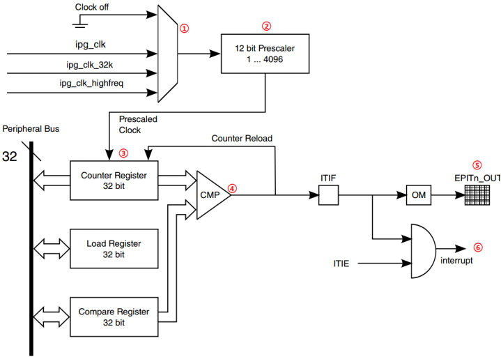
Figure 18.1 1 epit timer block diagram
Figure 18.1 The functions of each part in 1 are as follows:
① This is a multiplexer used to select the clock source of EPIT timer. EPIT has 3 clock sources to select, ipg_clk,ipg_clk_32k and ipg_clk_highfreq.
② This is a 12 bit frequency divider, which is responsible for frequency division of the clock source. The corresponding value of 12 bits is 04095, corresponding to 14096 frequency division.
③ The divided clock enters the EPIT. There are three important registers in the EPIT: count register (EPIT_CNR), load register (EPIT_LR) and comparison register (EPIT_CMPR). These three registers are 32 bits. EPIT is a down counter, that is, if you give it an initial value, it will decrease from the given initial value to 0. What is stored in the count register is the current count value. If EPIT works in the set and forget mode, when the value in the count register decreases to 0, EPIT will read the value from the load register to the count register again and start counting down again. The value stored in the comparison register is used to compare with the count value in the count register. If it is equal, a comparison event will be generated.
④ . comparator.
⑤ EPIT can set the pin output. If it is set, it will output the signal through the specified pin.
⑥ . generate comparison interrupt, that is, timing interrupt.
The EPIT timer has two working modes: set and forget and free running. The differences between the two working modes are as follows:
Set and forget mode: epitx_ When the RLD position of Cr (x = 1, 2) register is 1, EPIT works in this mode. In this mode, the counter of EPIT is loaded from register epitx_ The initial value is obtained in LR, and data cannot be written directly to the counter register. Whenever the counter counts to 0, epitx is loaded from the register_ The LR reloads the data into the counter and starts over and over again.
Free running mode: epitx_ EPIT works in this mode when the RLD bit of Cr register is cleared. When the counter counts to 0, it will start counting again from 0xfffffff instead of loading register epitx_ Get data from LR.
Next, let's take a look at several important registers of EPIT. The first is the configuration register epitx of EPIT_ Cr, the structure of this register is shown in Figure 18.1 As shown in Figure 2:
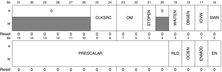
Figure 18.1 2 EPITx_ CR register structure diagram
Register EPITx_CR we use the following important bits:
CLKSRC(bit25:24): EPIT clock source selection bit, turn off the clock source when it is 0, select the periodic clock (ipg_clk) when it is 1, select the high frequency reference clock (ipg_clk_highfreq) when it is 2, and select the low frequency reference clock (ipg_clk_32k) when it is 3. In this routine, we set it to 1, that is, select IPG_ CLK as the clock source of EPIT, ipg_clk=66MHz.
PRESCALAR(bit15:4): EPIT clock source frequency division value. The setting range is 04095, corresponding to 14096 frequency division respectively.
RLD(bit3): EPIT working mode. It works in free running mode when it is 0 and set and forget mode when it is 1. The routine in this chapter is set to 1, that is, it works in set and forget mode.
OCIEN(bit2): enable bit of comparison interrupt. When it is 0, the comparison interrupt is closed, and when it is 1, the comparison interrupt is enabled. The comparison interrupt shall be enabled in the test of this chapter.
ENMOD(bit1): set the initial value of the counter. When it is 0, the initial value of the counter is equal to the value in the counter after closing the EPIT timer last time. When it is 1, it comes from the load register.
EN(bit0): EPIT enable bit, which turns off EPIT when it is 0 and enables EPIT when it is 1.
Register EPITx_SR structure is shown in Figure 18.1 As shown in Figure 3:

Figure 18.1 3 EPITx_ SR register structure diagram
Register EPITx_SR has only one valid bit, OCIF(bit0). This bit is the comparison interrupt flag bit. When it is 0, it indicates that no comparison event has occurred, and when it is 1, it indicates that a comparison event has occurred. After the comparison interrupt occurs, this bit needs to be cleared manually. This bit is cleared by writing 1.
Register EPITx_LR,EPITx_CMPR and EPITx_CNR is load register, comparison register and count register respectively. These three registers are used to store data, which is very simple.
The EPIT registers are introduced here. For a detailed description of these registers, please refer to section 24.6 on page 1174 of the I.MX6ULL reference manual. In this chapter, we use EPIT to generate timed interrupts, and then flip LED0 in the interrupt service function. Next, we take EPIT1 as an example to explain what steps are required to realize this function. The configuration steps of EPIT are as follows:
1. Set the clock source of EPIT1
Set register EPIT1_ CLKSRC(bit25:24) bit of Cr register selects the clock source of EPIT1.
2. Set frequency division value
Set register epit1_ PRESCALAR(bit15:4) bit of Cr register to set the frequency division value.
3. Set working mode
Set register epit1_ RLD(bit3) bit of Cr sets the working mode of EPTI1.
4. Set the initial value source of the counter
Set register epit1_ ENMOD(bit1) bit of Cr sets the initial value source of the counter.
5. Enable compare interrupt
We need to use the comparison interrupt, so we need to set register epit1_ OCIEN(bit2) bit of Cr, enabling comparison interrupt.
6. Set load and compare values
Set register epit1_ Load value and register epit1 in LR_ The comparison value in CMPR can determine the interrupt cycle of the timer through these two registers.
7. EPIT1 interrupt setting and interrupt service function writing
Enable the corresponding EPIT1 interrupt in GIC, register the interrupt service function, and set the interrupt priority if necessary. Finally, write the interrupt service function.
8. Enable EPIT1 timer
After configuring EPIT1, EPIT1 can be enabled through register EPIT1_ Set the EN(bit0) bit of CR.
Through the above steps, we have configured EPIT, and realized the flip of LED0 through the comparison interrupt of EPIT.
18.2 hardware principle analysis
The resources used in this test are as follows:
①,LED0.
② . timer EPTI1.
This experiment controls the lighting and extinguishing of LED0 through the interrupt of EPTI1. The hardware principle of LED0 has been introduced earlier.
18.3 preparation of experimental procedures
The routine path corresponding to this experiment is: development board CD - > 1, bare metal routine - > 10_ epit_ timer.
The experiment in this chapter is completed on the basis of the routine in the previous chapter. Change the project name to "epic_timer", then create a folder named "eptimer" under the bsp folder, and then create a new bsp in bsp / eptimer_ epittimer. C and bsp_epittimer.h these two documents. In bsp_ epittimer. Enter the following in H:
Example code 18.3 1 bsp_ epittimer. H document code
1  #ifndef _BSP_EPITTIMER_H
2  #define _BSP_EPITTIMER_H
3  /***************************************************************
4  Copyright © zuozhongkai Co., Ltd. 1998-2019. All rights reserved.
5  File name: bsp_epittimer.h
6  Author: Zuo Zhongkai
7  Version: V1.0 0
8  Description: EPIT timer driver header file.
9  Others: None
10 Forum: www.openedv.com com
11 Log: first version v1 0 created by Zuo Zhongkai on January 5, 2019
12 ***************************************************************/
13 #include "imx6ul.h"
14
15 /* Function declaration */
16 void epit1_init(unsigned int frac, unsigned int value);
17 void epit1_irqhandler(void);
18
19 #endif
	bsp_epittimer.h The file is simple, just some function declarations. Then in bsp_epittimer.c Enter the following in:
Example code 18.3.2 bsp_epittimer.c File code
/***************************************************************
Copyright © zuozhongkai Co., Ltd. 1998-2019. All rights reserved.
File name: bsp_epittimer.c
 Author: Zuo Zhongkai
 Version: V1.0 0
 Description: EPIT timer driver file.
Others: configure the EPIT timer to realize the interrupt processing function of the EPIT timer
 Forum: www.openedv.com com
 Log: first version v1 0 created by Zuo Zhongkai on January 5, 2019
***************************************************************/
1  #include "bsp_epittimer.h"
2  #include "bsp_int.h"
3  #include "bsp_led.h"
4
5  /*
6   * @description   	: Initialize the EPIT timer
7   *                      EPIT The timer is a 32-bit down counter, and the clock source uses ipg=66Mhz
8   * @param – frac	: Frequency division value, ranging from 0 to 4095, corresponding to 1 ~ 4096 frequency division respectively.
9   * @param - value 	: Countdown value.
10  * @return         	: nothing
11  */
12 void epit1_init(unsigned int frac, unsigned int value)
13 {
14  	if(frac > 0XFFF)
15      	frac = 0XFFF;
16  	EPIT1->CR = 0;  /* Clear CR register first */
17
18  	/*
19 	  	 * CR Register:
20       * bit25:24 01 Clock source selection: Peripheral clock=66MHz
21       * bit15:4  frac Frequency division value
22       * bit3: 1  When the counter reaches 0, reload the value from LR
23       * bit2: 1  Compare interrupt enable
24       * bit1:    1  The initial count value is derived from the LR register value
25       * bit0:    0  Close EPIT1 first
26       */
27  	EPIT1->CR = (1<<24 | frac << 4 | 1<<3 | 1<<2 | 1<<1);
28  	EPIT1->LR = value; 	/* Load register value 	*/
29  	EPIT1->CMPR = 0;    	/* Compare register values 	*/
30
31  	/* Enable the corresponding interrupt in GIC	*/
32  	GIC_EnableIRQ(EPIT1_IRQn);
33
34  	/* Register interrupt service function 		*/
35  	system_register_irqhandler(EPIT1_IRQn,
(system_irq_handler_t)epit1_irqhandler,
NULL);
36  	EPIT1->CR |= 1<<0;  /* Enable EPIT1 */
37 }
38
39 /*
40  * @description  	: EPIT Interrupt handling function
41  * @param          	: nothing
42  * @return         	: nothing
43  */
44 void epit1_irqhandler(void)
45 {
46  	static unsigned char state = 0;
47  	state = !state;
48  	if(EPIT1->SR & (1<<0))        	/* Judge the occurrence of comparison events 			*/
49  	{
50      	led_switch(LED0, state);    	/* The timer cycle expires and the LED is reversed 	*/
51  	}
52  	EPIT1->SR |= 1<<0;              	/* Clear interrupt flag bit 			*/
53 }
bsp_epittimer.c There are two functions in it epit1_init and epit1_irqhandler,namely EPIT1 Initialization functions and EPIT1 Interrupt handler function. epit1_init There are two parameters frac and value,among frac Is the frequency division value, value Is the load value. Set the comparison register to 0 in line 29, that is, when the counter counts down to 0, the comparison interrupt will be triggered, so the frequency division value frac and value The interrupt frequency can be determined. The calculation formula is as follows:
Tout = ((frac +1 )* value) / Tclk;
Of which:
Tclk: input clock frequency of EPIT1 (unit: Hz).
Tout: overflow time of EPIT1 (unit: S).
Line 38 sets the working mode of EPIT1 to set and forget, and the clock source is ipg_clk=66MHz. If we want to set the interrupt cycle of EPIT1 to 500ms, we can set the frequency division value to 0, that is, 1 frequency division. In this way, the clock entering EPIT1 is 66MHz. If you want to achieve an interrupt cycle of 500ms, the load register of EPIT1 should be 66 million / 2 = 33 million.
Function epit1_irqhandler is the interrupt handling function of EPIT1. This function reads EPIT1 first_ SR register to judge whether the current interrupt is a comparison event. If so, turn over the LED. Finally, the interrupt flag bit needs to be cleared when exiting the interrupt processing function.
Finally, main C file, in main C enter the following contents:
Example code 18.3 3 main. C document code
/**************************************************************
Copyright © zuozhongkai Co., Ltd. 1998-2019. All rights reserved.
File name: main c
 Author: Zuo Zhongkai
 Version: V1.0 0
 Description: bare metal experiment of I.MX6U development board 10 EPIT timer experiment
 Others: this experiment mainly studies how to use the EPIT timer provided by I.MX6UL
            EPIT Timer to realize the timing function and consolidate the interrupt knowledge of Cortex-A.
Forum: www.openedv.com com
 Log: first version v1 0 created by Zuo Zhongkai on January 4, 2019
**************************************************************/
1  #include "bsp_clk.h"
2  #include "bsp_delay.h"
3  #include "bsp_led.h"
4  #include "bsp_beep.h"
5  #include "bsp_key.h"
6  #include "bsp_int.h"
7  #include "bsp_epittimer.h"
8
9  /*
10  * @description  : main function
11  * @param        : nothing
12  * @return       : nothing
13  */
14 int main(void)
15 {
16  	int_init();                 	/* Initialization interrupt (must be called first!) 	*/
17  	imx6u_clkinit();            	/* Initialize system clock            	*/
18  	clk_enable();               	/* Enable all clocks            	*/
19  	led_init();                 	/* Initialize led             		*/
20  	beep_init();                	/* Initialize beep            		*/
21  	key_init();                 	/* Initialize key             		*/
22  	epit1_init(0, 66000000/2);  	/* Initialize EPIT1 timer, 1 Frequency Division
23                               			 * The count value is: 66 million / 2, i.e
24                               			 * The timing period is 500ms.
25                               			 */
26  	while(1)
27  	{
28      	delay(500);
29  	}
30
31 	 	return 0;
32 }
main.c There's only one inside main Function, line 22 calls the function epit1_init To initialize EPIT1,The frequency division value is 0, that is, 1, and the load register value is 66 million/2=33000000,EPIT1 The timer interrupt cycle is 500 ms. twenty-sixth~29 OK while There is only one delay function in the loop. Without other processing, the delay function can be removed.
18.4 compilation and download verification
18.4. 1 Write Makefile and link script
Change the TARGET in the Makefile to epic, add "BSP / epit imer" in incdir and SRCDIRS, and the modified Makefile is as follows:
Example code 18.4 1.1 makefile file code
1  CROSS_COMPILE  	?= arm-linux-gnueabihf-
2  TARGET          	?= epit
3
4  /* Omit other codes */
5
6  INCDIRS      	:=	imx6ul \
7                  		bsp/clk \
8                  		bsp/led \
9                  		bsp/delay  \
10                 		bsp/beep \
11                 		bsp/gpio \
12                 		bsp/key \
13                 		bsp/exit \
14                 		bsp/int \
15                 		bsp/epittimer
16
17 SRCDIRS          :=	project \
18                 		bsp/clk \
19                 		bsp/led \
20                 		bsp/delay \
21                 		bsp/beep \
22                 		bsp/gpio \
23                 		bsp/key \
24                 		bsp/exit \
25                 		bsp/int \
26                 		bsp/epittimer
27
28  /* Omit other codes */
29
30 clean:
31  rm -rf $(TARGET).elf $(TARGET).dis $(TARGET).bin $(COBJS) $(SOBJS)
In line 2, change the variable TARGET to "epic", that is, the TARGET name is "epic".
Line 15 adds the path to the EPIT1 driver header (. h) in the variable incdir.
Line 26 adds the path to the EPIT1 driver file (. c) in the variable SRCDIRS.
The linked script remains unchanged.
18.4. 2 compile and download
Use the Make command to compile the code. After the compilation is successful, use the software imxdownload to compile the completed epic Download the bin file to the SD card. The command is as follows:
chmod 777 imxdownload / / allow imxdownload to execute once
./ imxdownload epit.bin /dev/sdd / / burn to the SD card, not to the / dev/sda or sda1 device!
After successful burning, insert the SD card into the SD card slot of the development board, and then reset the development board. If the program runs normally, LED0 will flash on and off continuously with a cycle of 500ms.