1. Download and install AD
Below are two installation methods, you can choose any one you like
1.1 Installation Method 1
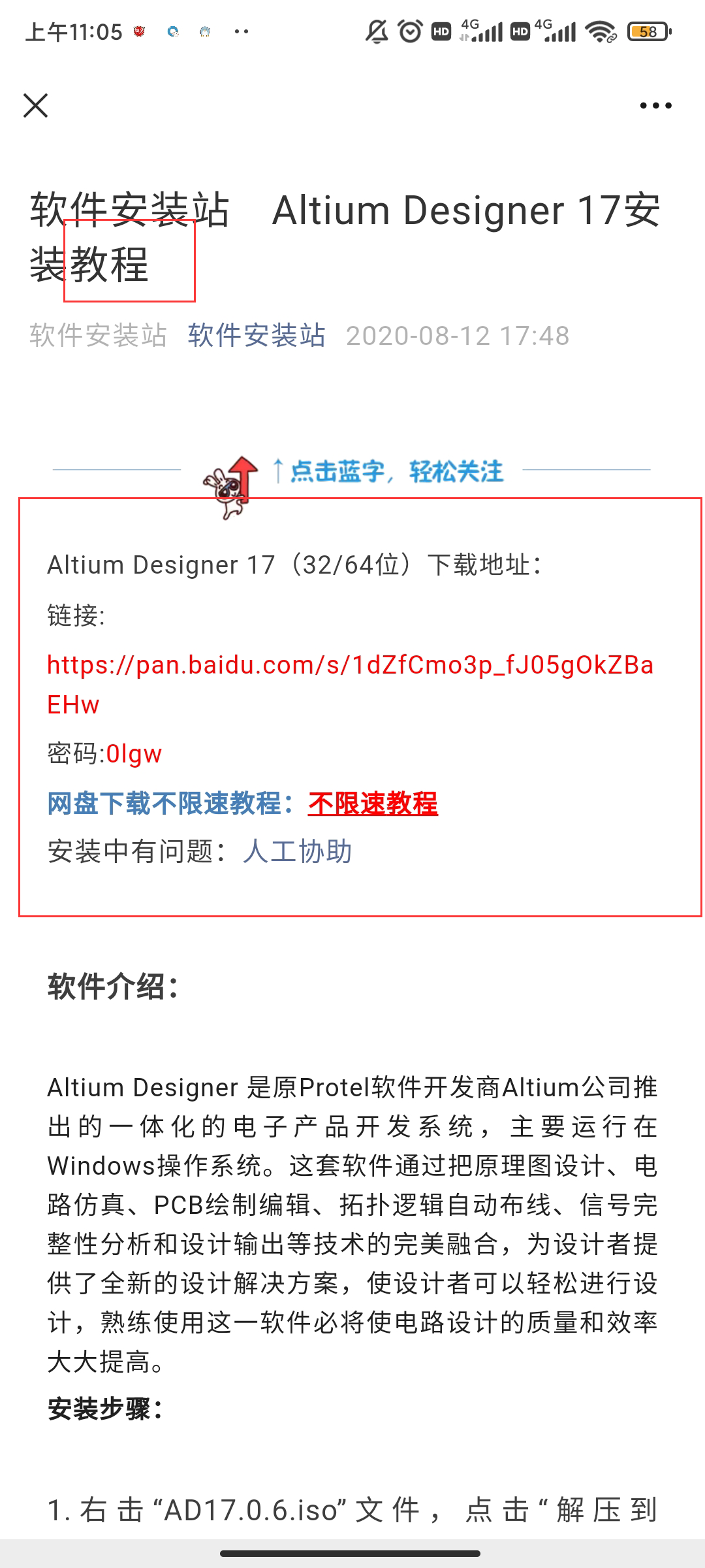
You can search for the public number of the Software Installation Station on WeChat and follow it. Then click in the software catalog to find Altium Designer to download the version you like.

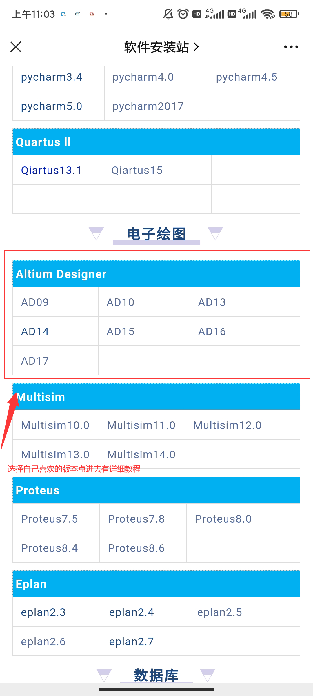
There are links to the disks and detailed download steps. If you have problems during installation, you can ask customer service directly
This way you can download it. This "software installation station" has detailed tutorials and if there are problems during the installation process, you can ask the customer service directly or ask them for remote assistance to install. It's really convenient to say that it's not advertising but the public number is really good. However, some versions may not have been updated.
1.2 Installation Method 2
You can refer to the following blog directly, the steps are detailed! However, it is recommended to choose the first installation method, because there may be problems, you can always ask customer service.
2. Draw STM32 Minimum System Schematic Diagram
2.1 Component Library
There is almost nothing missing from component libraries downloaded everywhere since AD. They are all in the following disks, which may be a little big:
Links: https://pan.baidu.com/s/1hTUUYVnjF_AfY-j3w2TMyQ (
Extraction Code: j7w4
2.2 New Project
Once installed, create a new PCB project
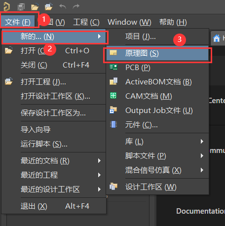
Click on File - > New - > Project
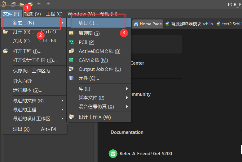
Then
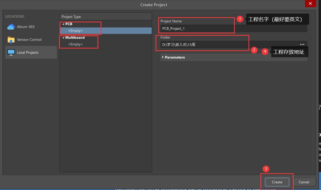
This creates the project, then creates component libraries, schematic diagrams, and so on.
Create schematic diagram: (Once created, press ctrl+S directly to save under the project directory just now. The name is best the same as the project name, but the suffix name can not be changed)
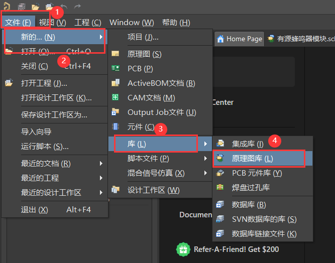
Create Component Library: (Once created, press ctrl+S directly to save under the project directory just now. The name is best the same as the project name, but the suffix name that comes with it cannot be changed)
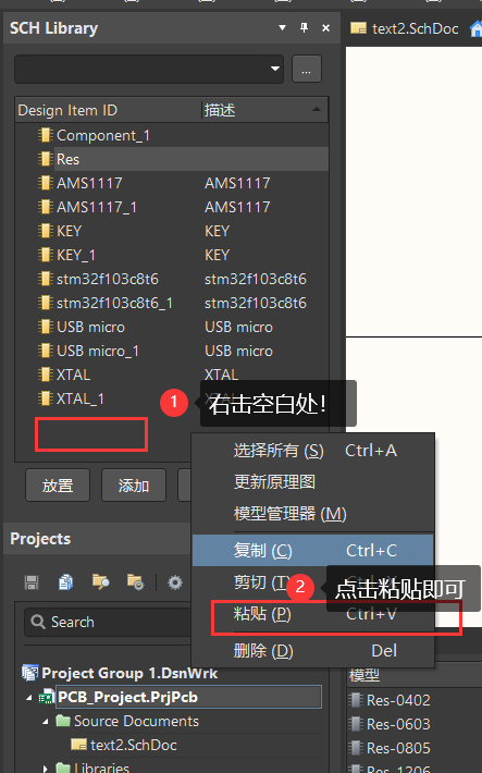
Components in the component library can choose to draw themselves or copy from other places. When pasting, be careful to click in the blank to paste
2.3 Drawing schematic diagrams
After the project is built and the components are imported, the schematic diagram can be drawn
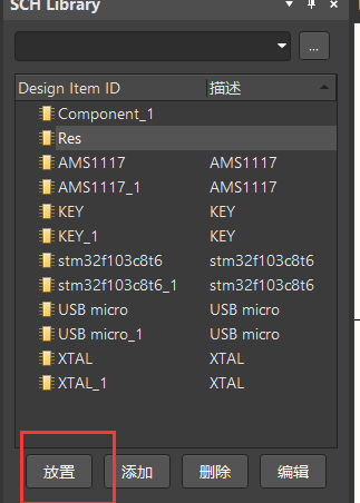
Click Place on the component library to place the component from the component library onto the schematic diagram (left Click to drop, right click to release the pending component)
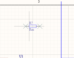
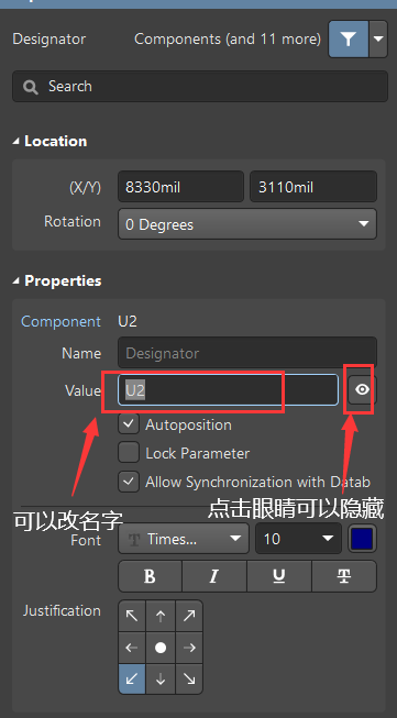
After placing the component, you can double-click the component or click on the component and then press the tab key to enter the settings window, edit the number name, and so on:
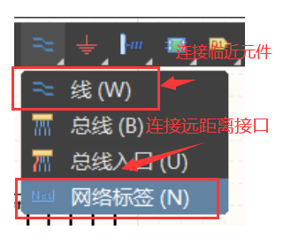
Click on the double wavy pattern above when the component is connected after placement. Right-click to select multiple connection modes. Generally only line and network labels are used:
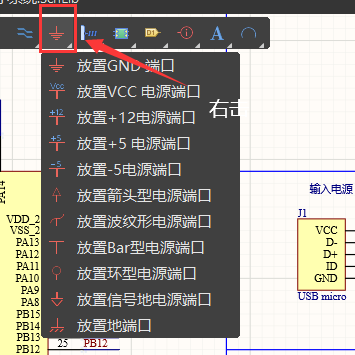
Power supply These choices are next to the wiring pattern: (Right-click to select different power supply, grounding, etc.)
Through the above learning, you should have almost mastered the use of AD!
Be careful! If you still feel confused, then offer a video of the AD tutorial for the B-stop geeks (this video and its details, which teaches AD usage by hand, but takes a long time. If you only draw a schematic, it's better to just look at the first half)
Here is the schematic drawing:
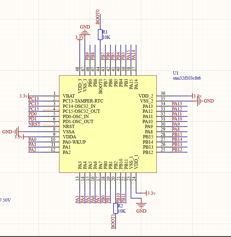
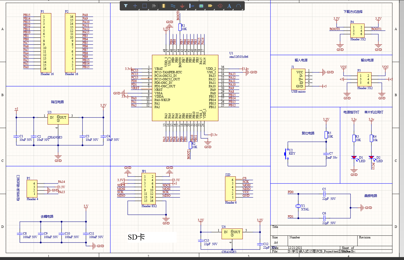
Minimum system circuit schematic for stm32:
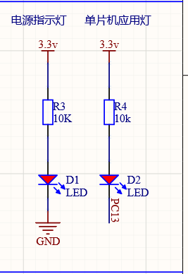
Indicator light:
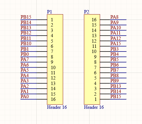
Draw needles:
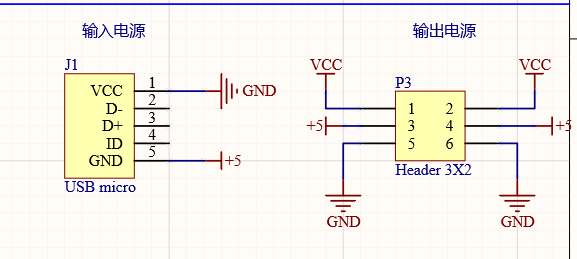
Power supply:
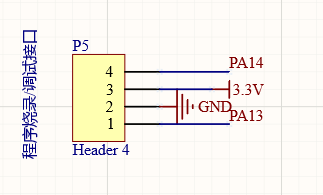
Program burning/debugging interface:
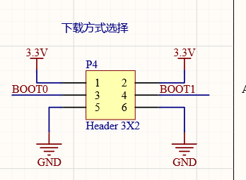
Download options:
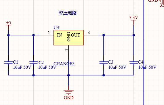
The voltage-reducing circuit:
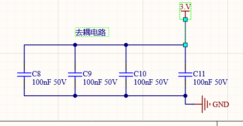
Decoupling circuit:
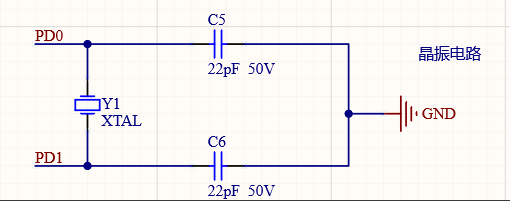
Crystal oscillator circuit:
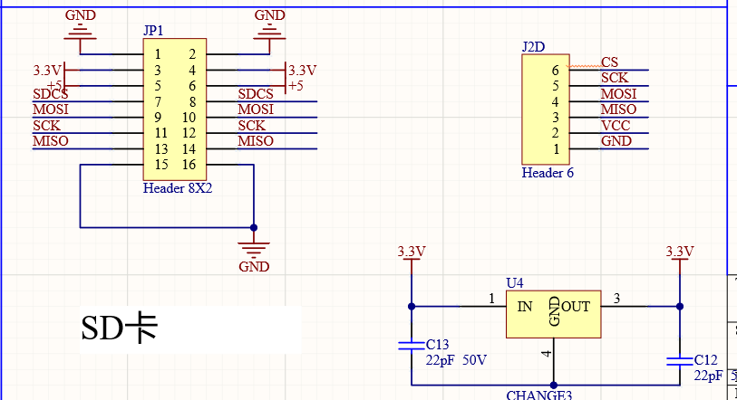
SD card schematic:
General schematic diagram:
SD card connection STM32 connection diagram:
3. Principle of SD card protocol
Introduction of 3.1 SD Card
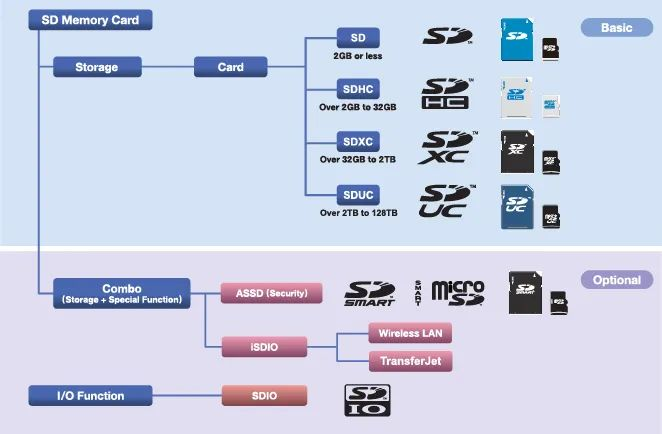
SD card (secure digital card) is a low-cost, non-volatile memory card format developed by the SD Card Association (SD card power loss data is not lost compared to RAM);
With the rapid development of electronic technology in this century, the demand for energy-saving and space-saving memory devices for this medium-sized model has been growing rapidly.
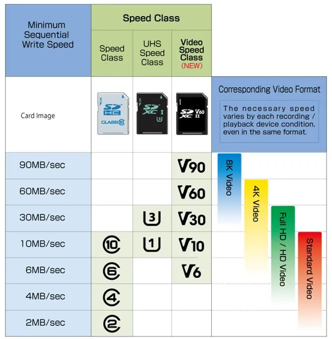
SD card has SDHC speed level and range; Level 2 (running at 2 MB/s); Level 4 (running at 4 MB/s); Level 6 (running at the highest 6 MB/s); Level 10 (running at the highest speed) 10 MB/sec;
The SDXC card runs at super high speed and at a speed of up to 30 Mb/s; There are also video speed levels, with data transfer rates as high as 90MB/s.
3.2SD card interface
SD card can run in SD bus mode or SPI bus mode, and SD can usually be driven by SDIO bus or SPI. Following is a brief introduction of SDIO mode and SPI mode, taking micro SD as an example.
microSD pin output, SD mode
| Pin | Pin Name | Signal function |
|---|---|---|
| 1 | DAT2 | Data Bit 2 |
| 2 | CD / DAT3 | Card Detection/Data Bit 3 |
| 3 | CMD | command line |
| 4 | Vdd | Power supply voltage 2.7v / 3.6v |
| 5 | Clk | Clock |
| 6 | VS | land |
| 7 | DAT0 | Data Bit 0 |
| 8 | DAT1 | Data Bit 1 |
microSD pin output, SPI mode
| Pin | Pin Name | Signal function |
|---|---|---|
| 1 | NC | No connection |
| 2 | /CS | Picture Selection |
| 3 | DI | Primary Output/Subordinate (MOSI) |
| 4 | Vdd | Power supply voltage 2.7v / 3.6v |
| 5 | Clk | Clock |
| 6 | Vss | land |
| 7 | DO | In/Out (MISO) |
| 8 | RSV | Reserved |
3.3 Agreement
In SD protocol, since command data line and data line are separate, we need to pay attention to the format of command transmission and the format of data transmission.
Command Transfer
The command is transmitted as a 48-bit packet through a two-way CMD pin.
These command packages include command indexes, variables, and CRC bits. This command is always sent through the host and eventually received by the SD card.
The returned response packet is also 48 bits.
The overall command is shown in the following figure;
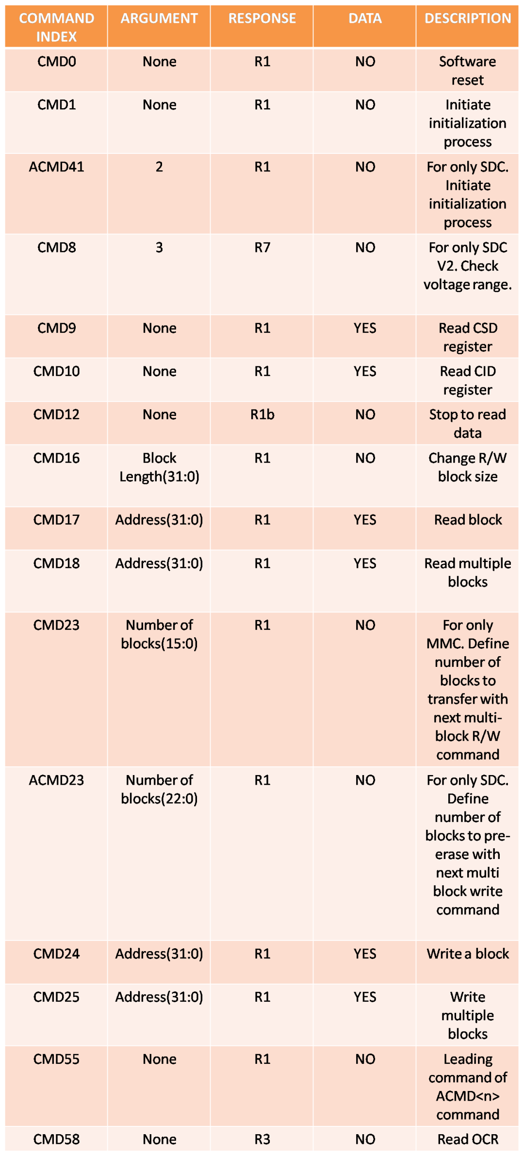
48-bit command format
Each command has a constant length of 6 bytes. The first byte is the addition of the command number and the number 64. For example: for CMD0: command number 0 + 64 = 64 = 0x40 (hexadecimal).
For CMD1: Hexadecimal command number 1 + 64 = 65 = 0x41.
Then there is a set of four bytes, called a parameter.
4. Data reading of SD card by STM32
4.1 Preparations
Prepare SD card module and SD card
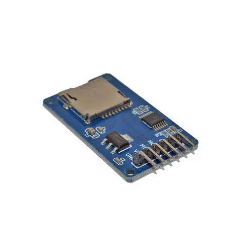
Internal structure:
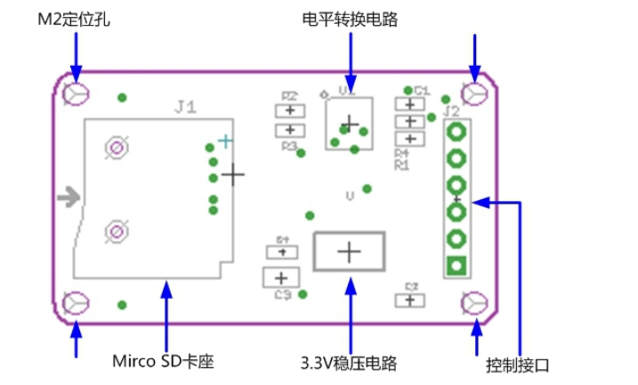
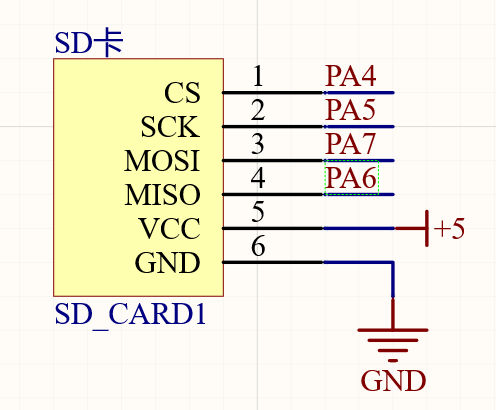
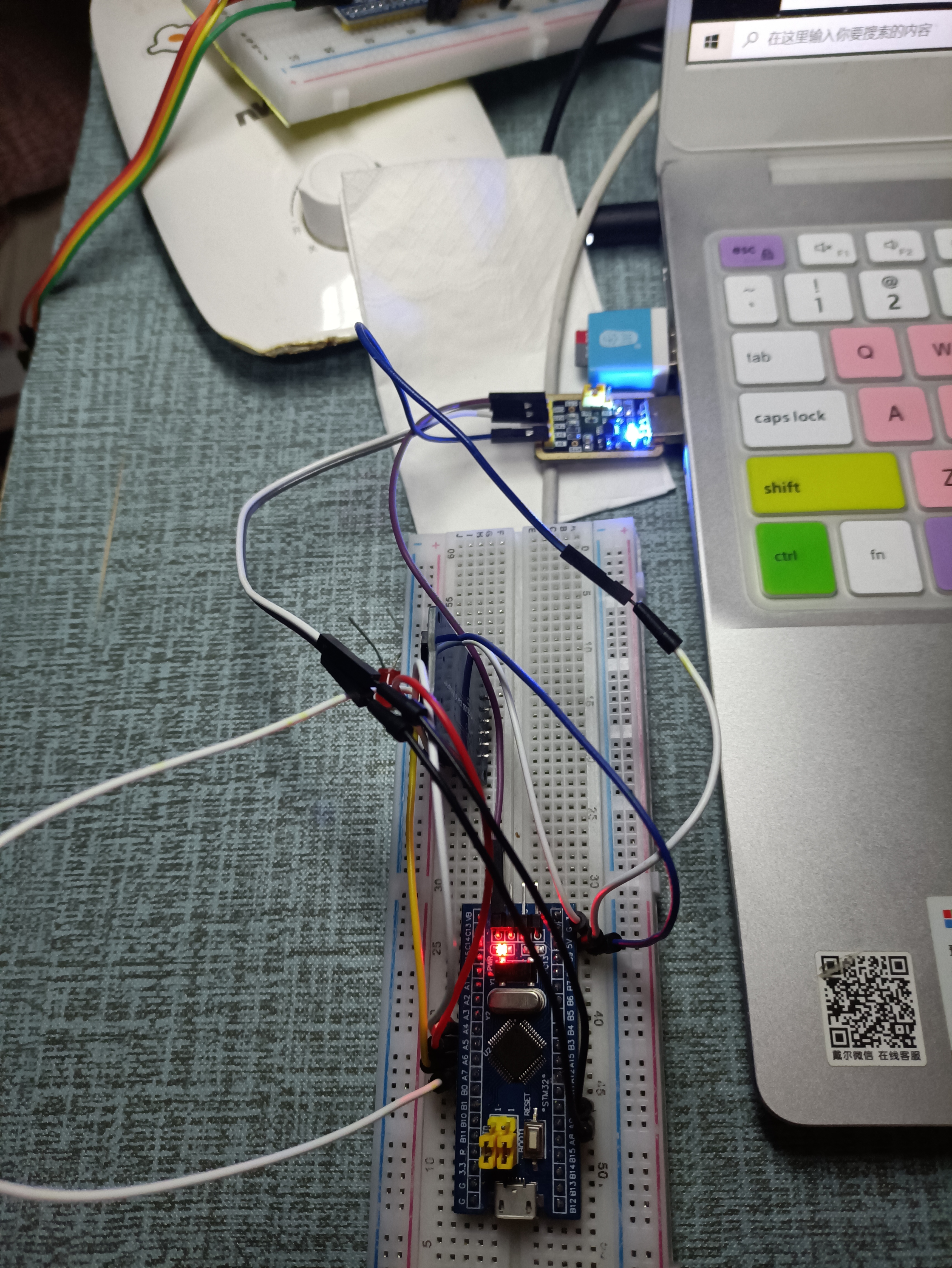
Connection between STM32 and SD card module:
| stm32 | SD card module |
|---|---|
| PA4 | SDCS |
| PA5 | SCK |
| PA7 | MOSI |
| PA6 | MISO |
| VCC | VCC |
| GND | GND |
Connected as shown in the diagram:
Since STM connects SD card modules, HAL library configuration follows:
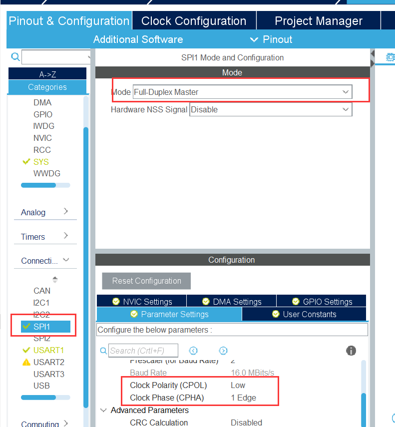
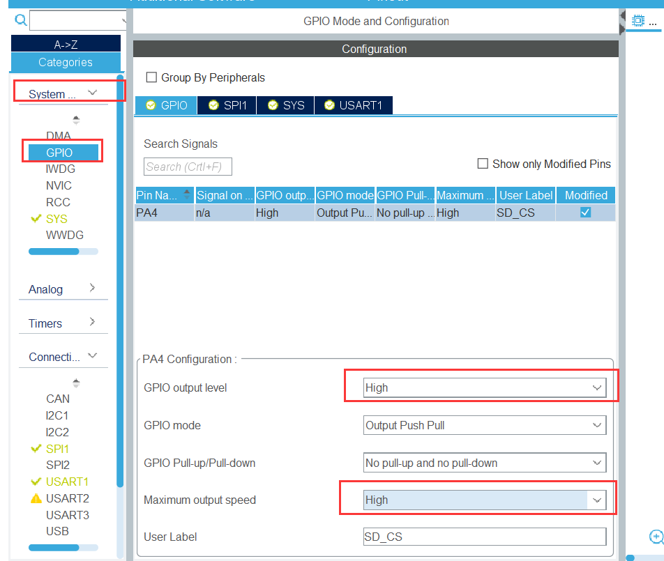
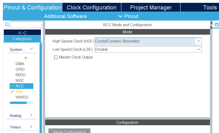
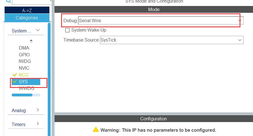
Then you can export the project address by making these changes

4.2 Code
main.c
/* USER CODE BEGIN Header */
/**
******************************************************************************
* @file : main.c
* @brief : Main program body
******************************************************************************
* @attention
*
* <h2><center>© Copyright (c) 2019 STMicroelectronics.
* All rights reserved.</center></h2>
*
* This software component is licensed by ST under Ultimate Liberty license
* SLA0044, the "License"; You may not use this file except in compliance with
* the License. You may obtain a copy of the License at:
* www.st.com/SLA0044
*
******************************************************************************
*/
/* USER CODE END Header */
/* Includes ------------------------------------------------------------------*/
#include "main.h"
#include "fatfs.h"
/* Private includes ----------------------------------------------------------*/
/* USER CODE BEGIN Includes */
#include "SDdriver.h"
/* USER CODE END Includes */
/* Private typedef -----------------------------------------------------------*/
/* USER CODE BEGIN PTD */
/* USER CODE END PTD */
/* Private define ------------------------------------------------------------*/
/* USER CODE BEGIN PD */
/* USER CODE END PD */
/* Private macro -------------------------------------------------------------*/
/* USER CODE BEGIN PM */
/* USER CODE END PM */
/* Private variables ---------------------------------------------------------*/
SPI_HandleTypeDef hspi1;
UART_HandleTypeDef huart1;
/* USER CODE BEGIN PV */
/* USER CODE END PV */
/* Private function prototypes -----------------------------------------------*/
void SystemClock_Config(void);
static void MX_GPIO_Init(void);
static void MX_SPI1_Init(void);
static void MX_USART1_UART_Init(void);
/* USER CODE BEGIN PFP */
/* USER CODE END PFP */
/* Private user code ---------------------------------------------------------*/
/* USER CODE BEGIN 0 */
int fputc(int ch, FILE *f)
{
HAL_UART_Transmit(&huart1, (unsigned char *)&ch, 1, 0xFFFF);
return ch;
}
uint16_t uart_value[3];
uint8_t aRxBuffer1; //uart rx buff
void WritetoSD(BYTE write_buff[],uint8_t bufSize);
char SD_FileName[] = "hello.txt";
uint8_t WriteBuffer[] = "01 write buff to sd \r\n";
//uint8_t test_sd =0; //ÓÃÓÚ²âÊÔ¸ñʽ»¯
uint8_t write_cnt =0; //дSD¿¨´ÎÊý
void WritetoSD(BYTE write_buff[],uint8_t bufSize)
{
FATFS fs;
FIL file;
uint8_t res=0;
UINT Bw;
res = SD_init(); //SD card initialization
if(res == 1)
{
printf("SD Card Initialization Failed! \r\n");
}
else
{
printf("SD Card initialization succeeded! Congratulations \r\n");
}
res=f_mount(&fs,"0:",1); //mount
// if(test_sd == 0) // For test formatting
if(res == FR_NO_FILESYSTEM) //No file system, formatting
{
// test_sd =1; // For test formatting
printf("No file system! \r\n");
res = f_mkfs("", 0, 0); //Format sd card
if(res == FR_OK)
{
printf("Successfully formatted! \r\n");
res = f_mount(NULL,"0:",1); //Unmount after formatting
res = f_mount(&fs,"0:",1); //remount
if(res == FR_OK)
{
printf("SD Card mounted successfully for file write test!\r\n");
}
}
else
{
printf("format failure! \r\n");
}
}
else if(res == FR_OK)
{
printf("Mount successful!\r\n");
}
else
{
printf("Mount failed!\r\n");
}
res = f_open(&file,SD_FileName,FA_OPEN_ALWAYS |FA_WRITE);
if((res & FR_DENIED) == FR_DENIED)
{
printf("Card Storage Full, Write Failed!\r\n");
}
f_lseek(&file, f_size(&file));//Ensure that word writes do not overwrite previous data
if(res == FR_OK)
{
printf("Open Successfully/Create file successful! \r\n");
res = f_write(&file,write_buff,bufSize,&Bw); //Write data to SD card
if(res == FR_OK)
{
printf("File written successfully! \r\n");
}
else
{
printf("File write failed! \r\n");
}
}
else
{
printf("fail to open file!\r\n");
}
f_close(&file); //Close File
f_mount(NULL,"0:",1); //unmount
}
void Get_SDCard_Capacity(void)
{
FRESULT result;
FATFS FS;
FATFS *fs;
DWORD fre_clust,AvailableSize,UsedSize;
uint16_t TotalSpace;
uint8_t res;
res = SD_init(); //SD¿¨³õʼ»¯
if(res == 1)
{
printf("SD¿¨³õʼ»¯Ê§°Ü! \r\n");
}
else
{
printf("SD¿¨³õʼ»¯³É¹¦£¡ \r\n");
}
/* ¹ÒÔØ */
res=f_mount(&FS,"0:",1); //¹ÒÔØ
if (res != FR_OK)
{
printf("FileSystem Mounted Failed (%d)\r\n", result);
}
res = f_getfree("0:", &fre_clust, &fs); /* ¸ùĿ¼ */
if ( res == FR_OK )
{
TotalSpace=(uint16_t)(((fs->n_fatent - 2) * fs->csize ) / 2 /1024);
AvailableSize=(uint16_t)((fre_clust * fs->csize) / 2 /1024);
UsedSize=TotalSpace-AvailableSize;
/* Print free space in unit of MB (assuming 512 bytes/sector) */
printf("\r\n%d MB total drive space.\r\n""%d MB available.\r\n""%d MB used.\r\n",TotalSpace, AvailableSize,UsedSize);
}
else
{
printf("Get SDCard Capacity Failed (%d)\r\n", result);
}
}
/* USER CODE END 0 */
/**
* @brief The application entry point.
* @retval int
*/
int main(void)
{
/* USER CODE BEGIN 1 */
/* USER CODE END 1 */
/* MCU Configuration--------------------------------------------------------*/
/* Reset of all peripherals, Initializes the Flash interface and the Systick. */
HAL_Init();
/* USER CODE BEGIN Init */
/* USER CODE END Init */
/* Configure the system clock */
SystemClock_Config();
/* USER CODE BEGIN SysInit */
/* USER CODE END SysInit */
/* Initialize all configured peripherals */
MX_GPIO_Init();
MX_SPI1_Init();
MX_FATFS_Init();
MX_USART1_UART_Init();
/* USER CODE BEGIN 2 */
HAL_UART_Receive_IT(&huart1,&aRxBuffer1,1); //enable uart
printf(" main \r\n");
Get_SDCard_Capacity(); //µÃµ½Ê¹ÓÃÄڴ沢ѡÔñ¸ñʽ»¯
/* USER CODE END 2 */
/* Infinite loop */
/* USER CODE BEGIN WHILE */
while (1)
{
WritetoSD(WriteBuffer,sizeof(WriteBuffer));
HAL_Delay(500);
WriteBuffer[0] = WriteBuffer[0] +10;
WriteBuffer[1] = WriteBuffer[1] +10;
write_cnt ++;
while(write_cnt > 10)
{
printf(" while \r\n");
HAL_Delay(500);
}
/* USER CODE END WHILE */
/* USER CODE BEGIN 3 */
}
/* USER CODE END 3 */
}
/**
* @brief System Clock Configuration
* @retval None
*/
void SystemClock_Config(void)
{
RCC_OscInitTypeDef RCC_OscInitStruct = {0};
RCC_ClkInitTypeDef RCC_ClkInitStruct = {0};
/** Initializes the CPU, AHB and APB busses clocks
*/
RCC_OscInitStruct.OscillatorType = RCC_OSCILLATORTYPE_HSI;
RCC_OscInitStruct.HSIState = RCC_HSI_ON;
RCC_OscInitStruct.HSICalibrationValue = RCC_HSICALIBRATION_DEFAULT;
RCC_OscInitStruct.PLL.PLLState = RCC_PLL_ON;
RCC_OscInitStruct.PLL.PLLSource = RCC_PLLSOURCE_HSI_DIV2;
RCC_OscInitStruct.PLL.PLLMUL = RCC_PLL_MUL16;
if (HAL_RCC_OscConfig(&RCC_OscInitStruct) != HAL_OK)
{
Error_Handler();
}
/** Initializes the CPU, AHB and APB busses clocks
*/
RCC_ClkInitStruct.ClockType = RCC_CLOCKTYPE_HCLK|RCC_CLOCKTYPE_SYSCLK
|RCC_CLOCKTYPE_PCLK1|RCC_CLOCKTYPE_PCLK2;
RCC_ClkInitStruct.SYSCLKSource = RCC_SYSCLKSOURCE_PLLCLK;
RCC_ClkInitStruct.AHBCLKDivider = RCC_SYSCLK_DIV2;
RCC_ClkInitStruct.APB1CLKDivider = RCC_HCLK_DIV1;
RCC_ClkInitStruct.APB2CLKDivider = RCC_HCLK_DIV1;
if (HAL_RCC_ClockConfig(&RCC_ClkInitStruct, FLASH_LATENCY_2) != HAL_OK)
{
Error_Handler();
}
}
/**
* @brief SPI1 Initialization Function
* @param None
* @retval None
*/
static void MX_SPI1_Init(void)
{
/* USER CODE BEGIN SPI1_Init 0 */
/* USER CODE END SPI1_Init 0 */
/* USER CODE BEGIN SPI1_Init 1 */
/* USER CODE END SPI1_Init 1 */
/* SPI1 parameter configuration*/
hspi1.Instance = SPI1;
hspi1.Init.Mode = SPI_MODE_MASTER;
hspi1.Init.Direction = SPI_DIRECTION_2LINES;
hspi1.Init.DataSize = SPI_DATASIZE_8BIT;
hspi1.Init.CLKPolarity = SPI_POLARITY_LOW;
hspi1.Init.CLKPhase = SPI_PHASE_1EDGE;
hspi1.Init.NSS = SPI_NSS_SOFT;
hspi1.Init.BaudRatePrescaler = SPI_BAUDRATEPRESCALER_2;
hspi1.Init.FirstBit = SPI_FIRSTBIT_MSB;
hspi1.Init.TIMode = SPI_TIMODE_DISABLE;
hspi1.Init.CRCCalculation = SPI_CRCCALCULATION_DISABLE;
hspi1.Init.CRCPolynomial = 10;
if (HAL_SPI_Init(&hspi1) != HAL_OK)
{
Error_Handler();
}
/* USER CODE BEGIN SPI1_Init 2 */
/* USER CODE END SPI1_Init 2 */
}
/**
* @brief USART1 Initialization Function
* @param None
* @retval None
*/
static void MX_USART1_UART_Init(void)
{
/* USER CODE BEGIN USART1_Init 0 */
/* USER CODE END USART1_Init 0 */
/* USER CODE BEGIN USART1_Init 1 */
/* USER CODE END USART1_Init 1 */
huart1.Instance = USART1;
huart1.Init.BaudRate = 115200;
huart1.Init.WordLength = UART_WORDLENGTH_8B;
huart1.Init.StopBits = UART_STOPBITS_1;
huart1.Init.Parity = UART_PARITY_NONE;
huart1.Init.Mode = UART_MODE_TX_RX;
huart1.Init.HwFlowCtl = UART_HWCONTROL_NONE;
huart1.Init.OverSampling = UART_OVERSAMPLING_16;
if (HAL_UART_Init(&huart1) != HAL_OK)
{
Error_Handler();
}
/* USER CODE BEGIN USART1_Init 2 */
/* USER CODE END USART1_Init 2 */
}
/**
* @brief GPIO Initialization Function
* @param None
* @retval None
*/
static void MX_GPIO_Init(void)
{
GPIO_InitTypeDef GPIO_InitStruct = {0};
/* GPIO Ports Clock Enable */
__HAL_RCC_GPIOA_CLK_ENABLE();
/*Configure GPIO pin Output Level */
HAL_GPIO_WritePin(SD_CS_GPIO_Port, SD_CS_Pin, GPIO_PIN_RESET);
/*Configure GPIO pin : SD_CS_Pin */
GPIO_InitStruct.Pin = SD_CS_Pin;
GPIO_InitStruct.Mode = GPIO_MODE_OUTPUT_PP;
GPIO_InitStruct.Pull = GPIO_NOPULL;
GPIO_InitStruct.Speed = GPIO_SPEED_FREQ_LOW;
HAL_GPIO_Init(SD_CS_GPIO_Port, &GPIO_InitStruct);
}
/* USER CODE BEGIN 4 */
/* USER CODE END 4 */
/**
* @brief This function is executed in case of error occurrence.
* @retval None
*/
void Error_Handler(void)
{
/* USER CODE BEGIN Error_Handler_Debug */
/* User can add his own implementation to report the HAL error return state */
/* USER CODE END Error_Handler_Debug */
}
#ifdef USE_FULL_ASSERT
/**
* @brief Reports the name of the source file and the source line number
* where the assert_param error has occurred.
* @param file: pointer to the source file name
* @param line: assert_param error line source number
* @retval None
*/
void assert_failed(uint8_t *file, uint32_t line)
{
/* USER CODE BEGIN 6 */
/* User can add his own implementation to report the file name and line number,
tex: printf("Wrong parameters value: file %s on line %d\r\n", file, line) */
/* USER CODE END 6 */
}
#endif /* USE_FULL_ASSERT */
/************************ (C) COPYRIGHT STMicroelectronics *****END OF FILE****/
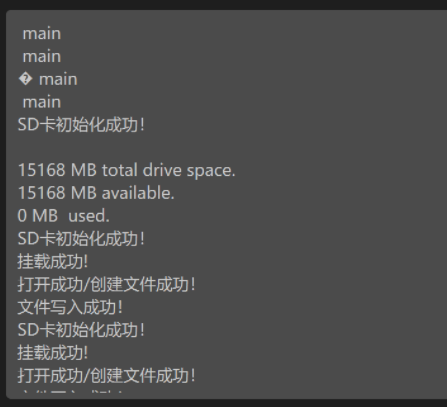
4.3 Burning Effect
Now burn the compiled hex file into the chip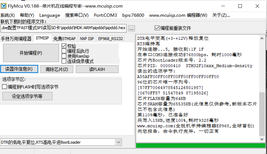
Then change the jumper cap, open the serial debugging assistant, the first burn only shows a Main, Metaphysical!
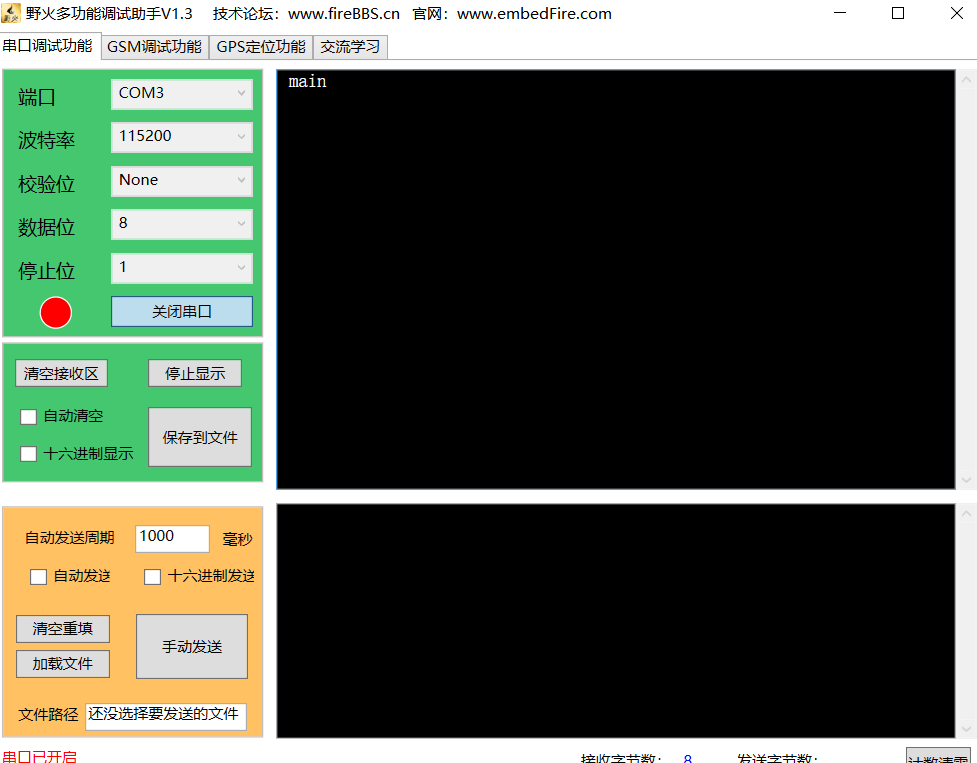
Nth time: I don't understand, and I only receive it back every time I get on the phone
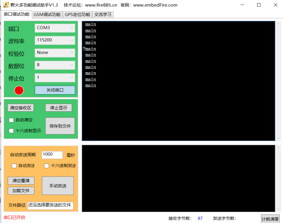
Then insert all the wires forcefully once. Change another wildfire debugging serial port
I don't understand
V. Summary
This experiment has shattered my mind. What's wrong with this serial port? The steps of the experiment itself are not very difficult. It may be a bit of a hassle when drawing a schematic, but they all went well after that, but! When the serial port is burned out, it is another story, either a line or the voltage is wrong so it is not displayed or something else is displayed.
Reference:
(74 messages) Various SD card parameters and interfaces_ Column on tiandiren111 - CSDN Blog