I Hardware scheme
Based on the relationship between distance and time in ultrasonic transmission, an ultrasonic liquid level detection system which can accurately measure the distance between two points is designed by using 8051 single chip microcomputer for control and data processing. And select water injection or drainage through the high and low opening of liquid level and control relay.
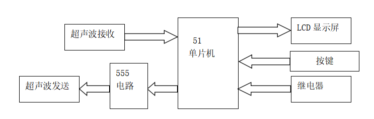
It is mainly designed by 51 single chip microcomputer + HC-SR04 ultrasonic sensor + LCD1602 liquid crystal + water pump + key + buzzer + relay; As shown in the figure:
II Design function
(1) In this design, the LCD has four letters, which are
H ----- set value of the highest water level of the container (not higher than the actual height)
L ----- set value of the lowest water level of the container
D -- actual height of container (can be set)
C - height of liquid in the container (in the actual demonstration, the closer the obstacle is to the probe, the larger the liquid crystal c display, because the obstacle is like the liquid level. If it is close to the probe, the water level is high)
(2) If the actual height of the container D is set to 1m, the height of liquid C can be measured up to 98cm, because the blind area of the probe is about 2cm. If D is set to 2m, the maximum height can be measured up to 1.98m.
(3) The key functions are: set key, increase key, decrease key, reset key.
(4) The functions of the three indicators are: Red - exceeding the set maximum water level H; yellow - lower than the set minimum water level L; green - between the maximum h and the minimum L.
(5) When the liquid level is higher or lower than the set value, the buzzer will alarm;
(6) When the liquid level is higher than the set value of the maximum water level, the drainage relay opens; when the liquid level is lower than the set value of the minimum water level, the water injection relay opens;
III Design schematic diagram
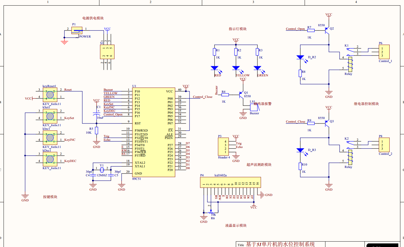
(1) The schematic diagram is mainly designed by AD software, as shown in the figure:
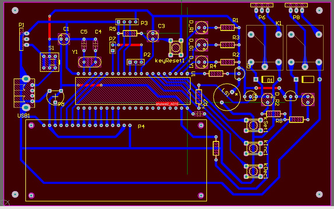
(2)PCB, as shown in the figure:
IV software design
Main program source code
/*********************************************************/
void main(void)
{
	initIO();			//Initialize IO port
	delay500ms(); 		//Start delay, leaving enough time for the device to enter the normal working state
	initLCD1602(); 	//LCD initialization
	putLineCharsToLCD1602(lineOne, 8, 8, "D:000cm ");	//Displays the distance (distance from the detection probe to the bottom of the reservoir) D
	putThreeCharToLCD1602(lineOne, 8 + 2, uiD);		//Display three digit values
	putLineCharsToLCD1602(lineOne, 0, 8, "H:000cm ");	//Displays the set maximum alarm water level H
	putThreeCharToLCD1602(lineOne, 0 + 2, uiH);		//Display three digit values
	putLineCharsToLCD1602(lineTow, 0, 8, "L:000cm ");	//Displays the set minimum alarm water level L
	putThreeCharToLCD1602(lineTow, 0 + 2, uiL);		//Display three digit values
	putLineCharsToLCD1602(lineTow, 8, 8, "C:000cm ");	//Displays the CURRENT current water level C

	initTimer0();		//Initialize timer 0
	initTimer1();

	//Valve action: initial drainage
	io_Control_Inlet = isio_Control_Inlet_OFF;
	io_Control_Outlet = isio_Control_Outlet_ON;
	g_flagSwitch = isNo;

	while(1)
	{
		io_US_TX = 1;			        //Start ultrasonic module signal
		delay10us();
		io_US_TX = 0;

		while(io_US_RX == 0);			//Wait for the timing to begin
		TR0 = 1;			    			//Start timer 0 and the timing starts
		IT1 = 1; 						//Set the input signal mode of external interrupt INT1 (1:Falling only valid for falling edge, 0:Low level valid for low level)
		EX1 = 1;                        //Enable external interrupt INT1

		while(EX1 == 1 && g_flag == isNo)//Wait for interrupt or timeout exit
		{
			uchar ucKeyValue = GetKey();					//Detecting keys while waiting
			if(ucKeyValue) execute_key_task(ucKeyValue);	//If a key is pressed, the key task is performed
		}

		if(CalculatedWaterLevel() == isNo) continue;		//Calculate the water level. If it is out of range, return to isNo and cycle again

		TR0 = 0;		//Temporarily turn off timer 0
		//Clear timer and count variables and flags
		TL0 = 0;
		TH0 = 0;
		g_flag = isNo;
		ucCount = 0;
		g_flag05s = isNo;

		TR0 = 1;		//Turn on timer 0
		while(g_flag05s == isNo)		//Delay 0.52 seconds to prevent the ultrasonic returned during this period from generating error messages, slow down the display changes and ensure the visual effect
		{
			uchar ucKeyValue = GetKey();
			if(ucKeyValue)
			{
				if(ucKeyValue == DATA_KEY_DEC)
				{
					g_flagBeepTimer = isNo;//Use the decrease key to cancel the alarm flag
				}

				execute_key_task(ucKeyValue);	//If a key is pressed, the key task is performed
			}

		}
		TR0 = 0;		//Temporarily turn off timer 0
		//Reset timer and reset flag
		TL0 = 0;
		TH0 = 0;
		g_flag = isNo;

		//-----------------------------------
		//Water tank cleaning tips:

		if(g_flagBeepTimer == isYes)
		{
			buzzerCall();
			//Use the decrease key to cancel the alarm flag

		}
		//-----------------------------------

	}
}
If you need information, please pay attention to the official account design of the microcontroller, and retrieve the information from the ultrasonic level.