What input mode is used to detect the input level signal?
Simply remember:
Detection port input low level 0 requires pull-up GPIO_InitStructure.GPIO_Mode = GPIO_Mode_IPU;
Detection port input high level 1 needs to use pull-down GPIO_InitStructure.GPIO_Mode = GPIO_Mode_IPD;
You don't know the schematic diagram of your external key and what level to detect?
The simplest way:
Use the voltmeter to connect the black ground and the red input terminal. It can be known by measurement.
No external key module?
Operation: 'all IO ports are external keys'!
You can even directly connect the DuPont line to VCC or ground to simulate the input high and low levels, playing a key effect.
After reading the first article, you should know how to initialize GPIO
So just talk about some new skills, that is, the above three points.
Here is an explanation of each point.
What input mode is used to detect the input level signal?
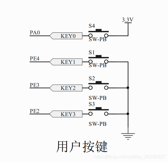
PE2/PE3/PE4 are grounded after being pressed, and the input is 0, so pull up is used
After PA0 is pressed, 3.3V voltage is applied, and the input is 1, so pull-down is used
You don't know the schematic diagram of your external key and what level to detect?
You can distinguish between VCC (middle) and GND (-) on the module, and the remaining Signal (S) is input to STM32 pin to detect the level.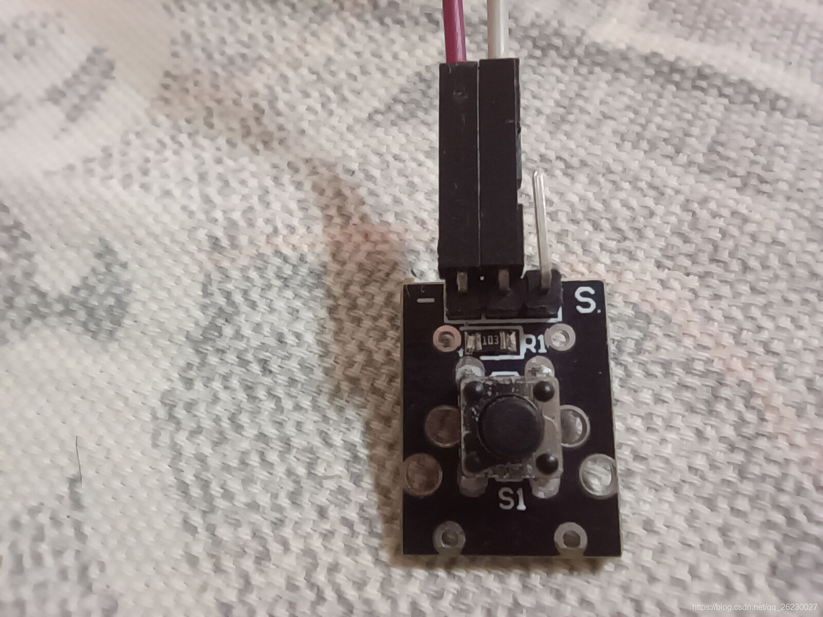
Check with voltmeter
The voltage at both ends of GND and Signal is 3.3V
0 after pressing
Isn't this the same as the three built-in buttons above?
So use the pull-up input
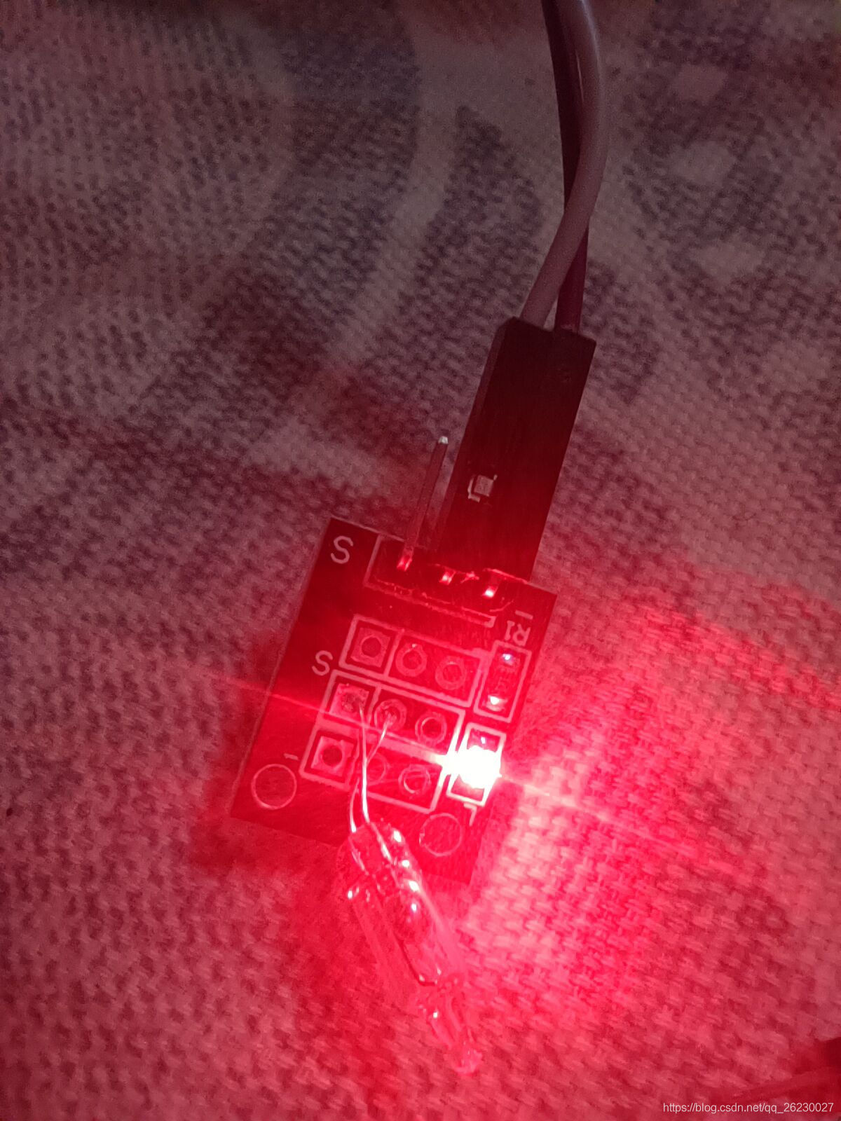
Mercury tilt detection module
Check with voltmeter
The voltage of GND and Signal sections is 3.3V
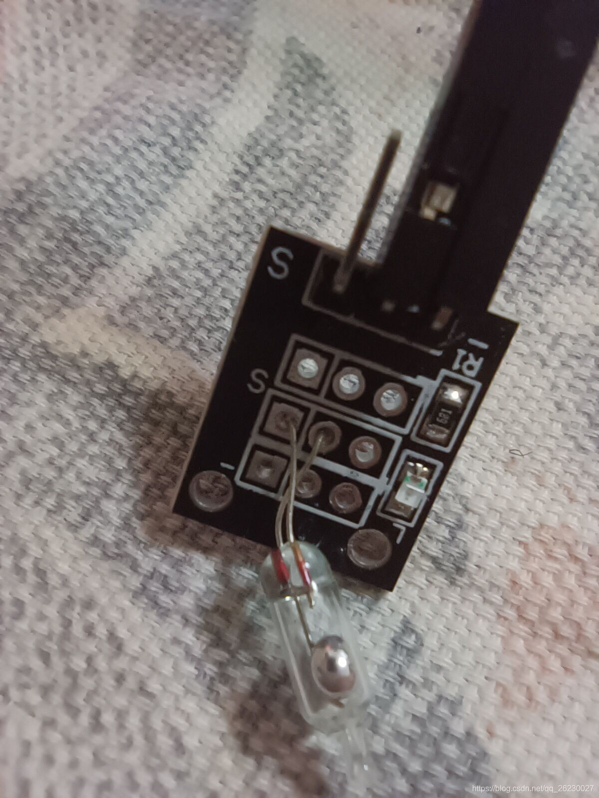
The indicator light turns on when Mercury is connected internally
Voltage at both ends of GND and Signal 0
The analogy with the above buttons is the same
No external key module?
Key detection is to detect the high and low level of a pin?
You can directly:
Pull up one pin
Grounding with DuPont wire is a key press
Pull down one pin
Connecting VCC with DuPont cable is also a key
What if you don't want to change the external key to PE9 in PA6?
Just modify the initialization related to PA6
The following are relevant codes
If you only need to change these three places, you must also change them all at the same time
RCC_APB2PeriphClockCmd(RCC_APB2Periph_GPIOA, ENABLE);

GPIO_InitStructure.GPIO_Pin = GPIO_Pin_6;

GPIO_Init(GPIOA, &GPIO_InitStructure);
/*-----------------------
File name: main c
 File Description: press the key to control the LED flashing and press the key
S1 Reverse LED2,
S2 Reverse LED3,
S4 At the same time, reverse LED2 and LED3
The_Key(External keys) make LED2 and LED3 flash for 5 times
---------------------------*/
#include "stm32f10x.h"
#include "led.h"
#include "delay.h"
#include "key.h"

int main(void)
{
  uint8_t j; //Define variables for subsequent for loops
  LED_Init();//LED initialization
  KEY_Init();//Built in key initialization
  The_Key_Init();//External key initialization
  Daley_Init();//Delay initialization
  while (1)
  {
		if(!S1)
		{
			Delay_ms(10);
			//Delay jitter elimination has been discussed in the 51 MCU tutorial button
			if(!S1)
			{
				 while(!S1);//Wait for the key to release
				 LED2_REV;
			}
		}
		if(!S2)
		{
			Delay_ms(10);
			if(!S2)
			{
				 while(!S2);
				 LED3_REV;
			}
		}
//Key 3 is similar to 1 and 2, which is omitted here
		if(S4)
		{
			Delay_ms(10);
			if(!The_Key)
			{
				 while(!The_Key);
				 LED2_REV;
				 LED3_REV;
			}
		}
		//External key PA6
		//You can also directly connect the DuPont line to VCC or ground to simulate the input high and low levels to achieve the key effect
	 if(!The_Key)
		{
			Delay_ms(10);
			if(S4)
			{
			while(S4);
				for(j=0;j<10;j++)
				{
				 LED2_REV;
				 LED3_REV;
				 Delay_ms(100);
				}
			}
		}
  }
}
/*------------------------------
File name: key c
 File Description: configure key initialization parameters
--------------------------------*/
#include "key.h"

void KEY_Init(void)//Internal keys PE2/PE3/PE4/PA0
{
	GPIO_InitTypeDef GPIO_InitStructure;
	//Open PE port clock
	RCC_APB2PeriphClockCmd(RCC_APB2Periph_GPIOE, ENABLE);
	//PE2,PE3,PE4 pin settings
	GPIO_InitStructure.GPIO_Pin = GPIO_Pin_2 | GPIO_Pin_3 | GPIO_Pin_4;
	//port speed
	GPIO_InitStructure.GPIO_Speed = GPIO_Speed_10MHz;
	//Port mode, this is the input pull-up mode
	GPIO_InitStructure.GPIO_Mode = GPIO_Mode_IPU;
	//Initialize the corresponding port
	GPIO_Init(GPIOE, &GPIO_InitStructure);
	//PA0 and PA6 pin settings
	//Turn on the PA port clock
	RCC_APB2PeriphClockCmd(RCC_APB2Periph_GPIOA, ENABLE);
	GPIO_InitStructure.GPIO_Pin = GPIO_Pin_0;
	//port speed
	GPIO_InitStructure.GPIO_Speed = GPIO_Speed_10MHz;
	//Port mode, this is the input drop-down mode
	GPIO_InitStructure.GPIO_Mode = GPIO_Mode_IPD;
	//Initialize the corresponding port
	GPIO_Init(GPIOA, &GPIO_InitStructure);
}

void The_KEY_Init(void)//I use PA6 to read the external keys
{
	GPIO_InitTypeDef GPIO_InitStructure;
	//Turn on the PA port clock
	RCC_APB2PeriphClockCmd(RCC_APB2Periph_GPIOA, ENABLE);
	//PA0 pin setting
	GPIO_InitStructure.GPIO_Pin = GPIO_Pin_6;
	//port speed
	GPIO_InitStructure.GPIO_Speed = GPIO_Speed_10MHz;
	// Port input low level 0 to pull up input high level 1 to pull down
	//Port mode, this is the input pull-up mode
	GPIO_InitStructure.GPIO_Mode = GPIO_Mode_IPU;
	//Initialize the corresponding port
	GPIO_Init(GPIOA, &GPIO_InitStructure);
}
/*------------------------------
File name: key h
--------------------------------*/
#ifndef __KEY_H
#define __KEY_H

#include "stm32f10x.h"

#define S1 GPIO_ReadInputDataBit(GPIOE,GPIO_Pin_4)
#define S2 GPIO_ReadInputDataBit(GPIOE,GPIO_Pin_3)
#define S3 GPIO_ReadInputDataBit(GPIOE,GPIO_Pin_2)
#define S4 GPIO_ReadInputDataBit(GPIOA,GPIO_Pin_0)
#define The_Key GPIO_ReadInputDataBit(GPIOA,GPIO_Pin_6)

void KEY_Init(void);

void The_KEY_Init(void);

#endif