This article is based on the wildfire guider F103 onboard LCD screen control, if there are any inaccuracies, welcome to refer to the orthogonal flow!
Preface
This article first briefly introduces the principle and initialization of STM32 external interrupt EXTI and LDV5 voice module, then uses external interrupt EXTI to control the on-board RGB light of wildfire compass F103, and finally extends it to LCD screen to realize the expectation of voice illuminating LCD screen.
1. STM32 External Interruption EXTI
1. What is External Interrupt EXTI
a. Exception (interrupt) type
F103 carries an exception response system at the kernel level, supporting a large number of system exceptions and external interrupts. There are eight system anomalies (10 if Reset and HardFault are counted), and 60 external interrupts. Except that the priority of individual exceptions is fixed, the priority of other exceptions is programmable. Specific system exceptions and external interrupts can be found in the standard library file stm32f10x.h This header file queries in IRQn_Type This structure contains all the exception declarations of the F103 series.
B. Introduction to EXTI
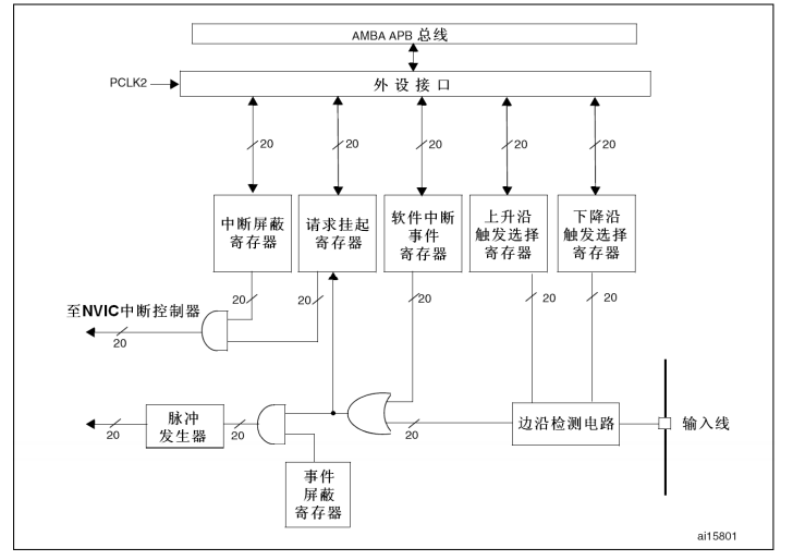
EXTI (External interrupt/event controller) - An external interrupt/event controller that manages 20 interrupt/event lines for the controller. Each interrupt/event line has an edge detector, which can detect the rising and falling edges of the input signal. EXTI implements a separate configuration of each interrupt/event line, which can be separately configured as an interrupt or event, as well as the attributes that trigger the event.
c.EXTI Function Block Diagram
2. Introduction to NVIC
NVIC is a nested vector interrupt controller that controls interrupt-related functions throughout the chip. It is tightly coupled with the kernel and is an peripheral inside the kernel.
The following is the NVIC structure definition from the firmware library header file:core_cm3.h
/** @addtogroup CMSIS_CM3_NVIC CMSIS CM3 NVIC
  memory mapped structure for Nested Vectored Interrupt Controller (NVIC)
  @{
 */
typedef struct
{
  __IO uint32_t ISER[8];                      /*!< Offset: 0x000  Interrupt Set Enable Register   Interrupt enabled register         */
       uint32_t RESERVED0[24];
  __IO uint32_t ICER[8];                      /*!< Offset: 0x080  Interrupt Clear Enable Register Interrupt Cleanup Register        */
       uint32_t RSERVED1[24];
  __IO uint32_t ISPR[8];                      /*!< Offset: 0x100  Interrupt Set Pending Register  Interrupt Enables Suspend Register         */
       uint32_t RESERVED2[24];
  __IO uint32_t ICPR[8];                      /*!< Offset: 0x180  Interrupt Clear Pending Register Interrupt Clear Suspended Register       */
       uint32_t RESERVED3[24];
  __IO uint32_t IABR[8];                      /*!< Offset: 0x200  Interrupt Active bit Register  Interrupt Significant Bit Register         */
       uint32_t RESERVED4[56];
  __IO uint8_t  IP[240];                      /*!< Offset: 0x300  Interrupt Priority Register (8Bit wide) Interrupt priority register*/
       uint32_t RESERVED5[644];
  __O  uint32_t STIR;                         /*!< Offset: 0xE00  Software Trigger Interrupt Register   Software Trigger Interrupt Register  */
}  NVIC_Type;
/*@}*/ /* end of group CMSIS_CM3_NVIC */
When configuring interrupts, we generally only use ISER, ICER and IP registers, ISER to enable interrupts, ICER to fail interrupts, and IP to set interrupt priority.
3. Initialize External Interrupt EXTI
a.EXTI initialization structure
typedef struct
{
  uint32_t EXTI_Line;               /*!< Specifies the EXTI lines to be enabled or disabled.
                                         This parameter can be any combination of @ref EXTI_Lines */

  EXTIMode_TypeDef EXTI_Mode;       /*!< Specifies the mode for the EXTI lines.
                                         This parameter can be a value of @ref EXTIMode_TypeDef */

  EXTITrigger_TypeDef EXTI_Trigger; /*!< Specifies the trigger signal active edge for the EXTI lines.
                                         This parameter can be a value of @ref EXTIMode_TypeDef */

  FunctionalState EXTI_LineCmd;     /*!< Specifies the new state of the selected EXTI lines.
                                         This parameter can be set either to ENABLE or DISABLE */
}EXTI_InitTypeDef;
- EXTI_Line:EXTI interrupt/event line selection, optional EXTI0 to EXTI19.
- EXTI_ Mode:EXTI mode selection, optionally generating an interrupt (EXTI_Mode_Interrupt) or an event (EXTI_Mode_Event).
- EXTI_ Trigger:EXTI Edge Trigger event, optional Up Edge Trigger_Rising, Down Edge Trigger_Falling, or Up Edge and Down Edge Trigger (EXTI_Trigger_Rising_Falling).
- EXTI_LineCmd: Controls whether the EXTI line is enabled, optionally ENABLE or DISABLE.
b. Define the port of EXTI in a macro-defined way
Below is bsp_exti.h file, which defines the GPIO port, port clock, and GPIO connected to the SCL clock line.
#ifndef __BSP_EXTI_H
#define __BSP_EXTI_H


#include "stm32f10x.h"

#define INT_GPIO_PORT 	 GPIOD 			              /*  GPIO Port*/
#define INT_GPIO_CLK 	     RCC_APB2Periph_GPIOD 		/*  GPIO Port Clock*/
#define INT_GPIO_PIN 	   	 GPIO_Pin_2 			        /*  GPIO */connected to SCL clock line

void EXIT_Int_Config(void);


#endif /* __BSP_EXTI_H */
c. Initialize EXTI function
void EXIT_Int_Config(void)
{
		//Initialize Structures
		GPIO_InitTypeDef GPIO_InitStructure;
	    EXTI_InitTypeDef EXTI_InitStructure;

		//Configure interrupt priority
		EXTI_NVIC_Config();

	  // Initialize GPIO
		RCC_APB2PeriphClockCmd( INT_GPIO_CLK, ENABLE);
		GPIO_InitStructure.GPIO_Pin = INT_GPIO_PIN;
		GPIO_InitStructure.GPIO_Mode = GPIO_Mode_IN_FLOATING;
		GPIO_Init(INT_GPIO_PORT, &GPIO_InitStructure);

		// Initialize EXTI
		RCC_APB2PeriphClockCmd( RCC_APB2Periph_AFIO, ENABLE);
		GPIO_EXTILineConfig(GPIO_PortSourceGPIOD, GPIO_PinSource2);

		EXTI_InitStructure.EXTI_Line = EXTI_Line2;
		EXTI_InitStructure.EXTI_Mode = EXTI_Mode_Interrupt;
		EXTI_InitStructure.EXTI_Trigger = EXTI_Trigger_Rising;
		EXTI_InitStructure.EXTI_LineCmd = ENABLE;
		EXTI_Init(&EXTI_InitStructure);

}
d. Nested Vector Interrupt Controller NVIC Configuration
static void EXTI_NVIC_Config(void)
{
		NVIC_InitTypeDef NVIC_InitStructure;

		NVIC_PriorityGroupConfig(NVIC_PriorityGroup_1);

		NVIC_InitStructure.NVIC_IRQChannel = EXTI2_IRQn;
		NVIC_InitStructure.NVIC_IRQChannelPreemptionPriority = 1;
	  NVIC_InitStructure.NVIC_IRQChannelSubPriority = 1;
		NVIC_InitStructure.NVIC_IRQChannelCmd = ENABLE;
		NVIC_Init(&NVIC_InitStructure);
}
2. LDV5 voice module
1. Introduction
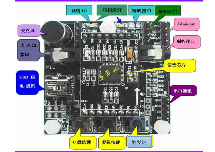
After connecting the voice module to the computer with a USB cable, the power-on voice will be broadcast. The three keys of the module from left to right are the U key, reset key and trigger key. After pressing the button on the U drive, the computer will read the files in the TF card inserted in the voice module. If we need to change the program of the voice module, we need to give the specific file contents in the TF card more. When the reset key is pressed, the voice module will be reset. The trigger button needs to be used in conjunction with the mode of the voice module and can be used as one of the trigger conditions.
The voice module reserves eight I/O ports to control the high and low level changes of I/O ports (high level is 3.3V) for further operation. At the same time, there is a serial port in the lower right of the voice module, which can connect the serial port of the single-chip computer for communication.
Note: RXD, TXD need cross connection; When connecting with single-chip computer, need common ground.
2. Intra-system call file introduction (cannot be deleted or renamed)
The following files in the TF card inserted into the voice module are called files within the system and cannot be deleted or renamed.
a. Main menu file - Fydz. Ini
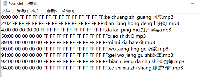
(1) The number at the beginning of each line is the menu file number.
The serial number 0 is the "password keyword", which is the name called out in password mode. This name must be stored in the serial number 0. Other meanings are the same as common keywords.
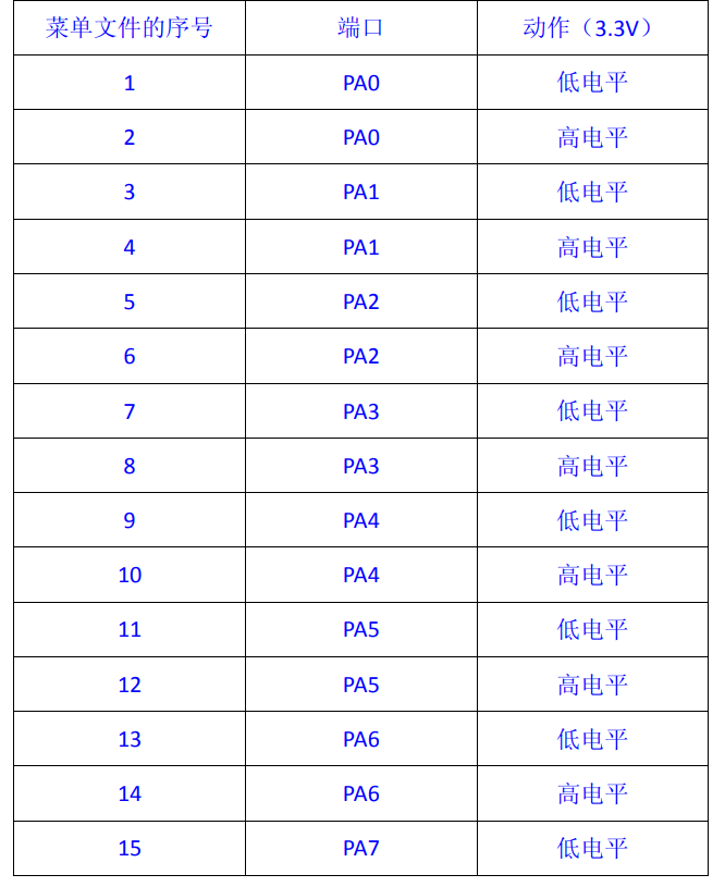
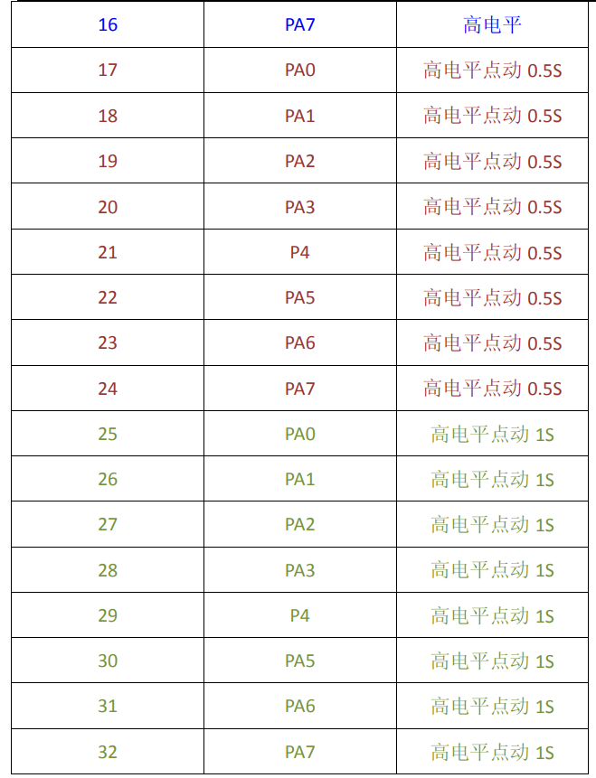
Serial number 1-88 is a "general keyword". Serial number 1-32 can control the change of I/O port level. Eight IO ports, PA0-PA7, are reserved on the module. Users only need to set the corresponding serial number of menu files in TF card to make use of IO port. Each port has high level, low level, high level 0.5s point, high level 1s point function.
The serial number 89 is "Exit keyword", which means we can use to return the system to the main menu or exit the operation. For example, if we are in a secondary menu, you can add the name 89 to let him jump out of the secondary menu and go back to the main menu to stay on standby. Or if you recognize the password in password mode and can no longer operate, you can use this command to stop the operation. This 89-numbered keyword can be customized and modified, just like other general keywords.
The serial number 90-99 is a total of 10 serial numbers. This is the serial number that enters the secondary menu. Its keywords can be modified by themselves and written like other general keywords. For example, the system will automatically enter T90 after recognizing the need for 90 keyword. In the second-level menu text of txt, this is the only keyword that can be recognized in this text. The original main menu keyword can no longer be recognized. The system is only in the current T90. TXT menu text works, of course, we can say 89 ordinal command back to the main menu, or go to other 91-99 menus, just say the corresponding ordinal command, and note that the corresponding file exists in the TF card.
(2) Debugging information for serial port in the middle of each line.
Serial debugging information is composed of 15 hexadecimal digits, read from left to right. If three FFs appear in a row, the data terminates. Serial data is all data before three consecutive FFs and is output through the serial communication port on the module.
(3) The trigger condition and audio response end of each line
The last part is the trigger condition of this line command, which is executed when the voice module is waked up and the trigger condition is recognized. Trigger condition is phonetic, for example "open screen" is "da kai ping mu", followed by. mp3 file, in order to trigger the audio response, note that this mp3 file needs to be present in the TF card.
b. System parameter profile - parameter.ini
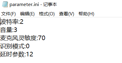
1. Baud rate
The baud rate is a communication speed parameter adjustment for serial communication function with the following values:
1------4800bps
2------9600bps
3------19200bps
4------57600bps
5------115200bps
The different sequence numbers above represent different baud rate values and default is 9600bps.
2. Volume
The volume is adjusted to the volume adjustment parameters of the speaker, which are as follows:
Parameter range: 0-15; 0: Minimum volume 15: Maximum volume
3. Microphone sensitivity
Microphone sensitivity is the adjustment of recognition distance and recognition rate. Normally, we do not make any adjustments. Interest can adjust the test, but the effect may not be improved. Specific parameters are as follows:
Parameter range: 1-99
1: Minimum sensitivity 99: Maximum sensitivity
Explanation: The higher the sensitivity, the farther the recognition distance, but the higher the misrecognition rate, the opposite;
4. Recognition Mode
The speech module has three recognition modes, password mode, normal mode, and
Key mode, different modes have different functions, the parameter values are as follows:
Parameter value: 0 - Password mode
1 - Normal mode
2 - Key mode (combined with trigger button)
Password mode: that is, each time you recognize it, you need to shout a first-level password, such as "Little Rock" after shouting a first-level password, no pronunciation will automatically exit around 10 seconds. If pronunciation occurs, you can restore the timing and wait until he quits or quits automatically. (default mode, effectively improve anti-jamming ability and practicability)
Normal mode: This mode does not need to shout a first-level password, but can directly shout a second-level password operation without delay wait and exit functions. (Used in quiet environment, noise is prone to trigger by mistake)
Key mode: The key mode and password mode are similar, only the key module needs to press the key, while the password mode is to shout a level one password, all the same.
5. Delay parameters
Delay parameter is a delay wait function in password mode and key mode. For example, if the default parameter is 12, the delay wait time is about 10 seconds. As you modify this parameter, you can change the wait time. The larger the value, the longer the wait time. This delay is only a reference to the delay time and is not an absolutely accurate time parameter.
c. System prompt Audio mp3 file
sys_sound.mp3 - - System boot sound (name cannot be changed, content can be replaced)
knock.mp3--------------------------- Key mode, key press prompt sound (same as above)
exit.mp3-------------- Exit prompt (same as above)
3. Speech Control LCD Screen Lighting
1. Connection
Depending on interrupt initialization, set port D, pin 2 as interrupt trigger pin, connect voice module PA0.
Through voice triggering, the PA0 port of the voice module is converted from low level to high level, and the rising edge level is obtained. The single chip computer is triggered to interrupt and enter the interrupt program (in the stm32f10x_it.c file) to light up the RGB lamp or LCD screen.
2. Interrupt program (LCD screen)
First, in the initialization file of the LCD screen, find the GPIO that controls the backlight of the LCD screen, and the function that controls the backlight of the LCD screen. Operate the function so that the LCD screen backlight does not light up (i.e. cannot be enabled) first, and then interrupt the function, if it enters an interrupt, let the LCD screen backlight light light up (even if it can).
a. Configure LCD backlight control pin BK
	/* Configure LCD backlight control pin BK*/
	GPIO_InitStructure.GPIO_Mode = GPIO_Mode_Out_PP;
	GPIO_InitStructure.GPIO_Speed = GPIO_Speed_50MHz;

	GPIO_InitStructure.GPIO_Pin = ILI9341_BK_PIN;
	GPIO_Init ( ILI9341_BK_PORT, & GPIO_InitStructure );
b.ILI9341 Backlight LED Control Function
/**
 * @brief  ILI9341 Backlight LED control
 * @param  enumState : Determine if backlight LED is enabled
  *   This parameter is one of the following values:
  *     @arg ENABLE :Enable backlight LED
  *     @arg DISABLE :Disable backlight LED
 * @retval nothing
 */
void ILI9341_BackLed_Control ( FunctionalState enumState )
{
	if ( enumState )
		GPIO_ResetBits ( ILI9341_BK_PORT, ILI9341_BK_PIN );
	else
		GPIO_SetBits ( ILI9341_BK_PORT, ILI9341_BK_PIN );

}
c.ILI9341 initialization function (backlight control not enabled)
/**
 * @brief  ILI9341 Initialize the function, which must be called if lcd is to be used
 * @param  nothing
 * @retval nothing
 */
void ILI9341_Init ( void )
{
	ILI9341_GPIO_Config ();
	ILI9341_FSMC_Config ();
	ILI9341_BackLed_Control ( DISABLE );
	ILI9341_Rst ();
	ILI9341_REG_Config ();

	//Set the Default scan direction, where 6 modes are the default display direction for most LCD routines
	ILI9341_GramScan(LCD_SCAN_MODE);
}
d.EXTI interrupt function (enable backlight)
void EXTI2_IRQHandler(void)
{
	if(EXTI_GetITStatus(EXTI_Line2) != RESET)
	{
		GPIO_ResetBits ( ILI9341_BK_PORT, ILI9341_BK_PIN );
	}
	EXTI_ClearITPendingBit(EXTI_Line2);
}
Summary and Improvement
This scheme achieves the illumination of LCD screen controlled by voice, and achieves the effect of human-computer interaction. The overall difficulty is not great.
Option 2: You can use the serial communication of the voice module to communicate with stm32. This effect can also be achieved when the voice module sends a hex data to the single chip computer, which receives the serial data and then responds accordingly.