Reference: oled display temperature and humidity based on stm32 software IIC
Author: ZPZ DayUp
Release time: 2021-07-25 20:52:43
website: https://blog.csdn.net/m0_56197680/article/details/119077076?spm=1001.2014.3001.5501
IIC communication
IIC physical layer
IIC protocol introduction
characteristic:
Due to its few pins, simple hardware implementation and strong scalability, it does not need external transceiver equipment of uasrt and can communication protocol. Now it is widely used in the communication between multiple integrated circuit IC s (chips) in the system.
Communication mode:
Half duplex communication mode
IIC bus system architecture (IIC physical layer)
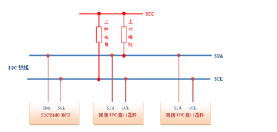
Explanation of the above figure
1. Only two bus lines are used for an IIC bus,
A bidirectional serial data line (SDA) used to represent data
A serial clock line (SCL), which is used for data transceiver synchronization.
2. It is a bus that supports multiple devices. " "Bus" refers to the signal line shared by multiple devices. In an IIC communication bus, multiple IIC communication devices can be connected to support multiple communication hosts and multiple communication slaves. Each device has an independent address. The host can access the slave by accessing different addresses
3. The bus is connected to the power supply VCC by the pull-up resistor. When the bus equipment is in the idle state, the high resistance state appears. At this time, the pull-up resistor pulls the bus to the high level
4. When multiple host devices occupy the bus at the same time, arbitration will be used to decide who occupies the bus in order to prevent conflict
IIC bus classification
Software IIC: generally configure GPIO pins, use software to control pin status and simulate IIC communication process
Hardware IIC: the IIC peripherals on the corresponding chip have corresponding IIC drive circuits, and the IIC pins used are also special
The difference between the two
1. The speed of hardware IIC is much higher than that of software IIC, but the hardware IIC is limited by pins and is not flexible.
2. Software IIC simulates the working mode of registers by configuring GPIO, while hardware IIC directly calls internal registers for configuration.
To sum up, it can be summarized as follows
1. The usage of hardware IIC is complex, and the simulation IIC process is clearer
2. Hardware IIC is faster than simulation
3. The analog iic can be on any pin, and the hardware IIC is on the fixed pin
IIC protocol layer
Some states of IIC data transmission process (IIC protocol layer)
① Idle state
When both SDA and SCL of IIC bus are at high level, this state is specified as idle state, and the corresponding output state is high resistance state (the output effector of each field device is cut off, resulting in large resistance of the FET), and the level is pulled up by the pull-up resistance.
② Start signal and cut-off signal
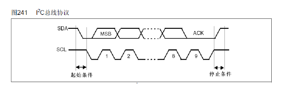
As shown in the figure, the starting condition is that SDA (data bus) changes from high level to low level and the falling edge jumps. The SCL (clock bus) remains high.
The termination condition is that SDA changes from low level to high level and the jump of rising edge. SCL remains high.
③ Response signal
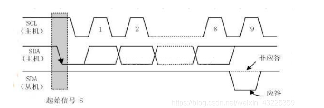
When a byte (8 bits) is transmitted, the data line is released in bit 9, a reply signal (ACK) is returned by the data line of the receiving device, and it is specified as a valid reply when it is low level. Combined with the pictures, it can be summarized as follows
The requirement for the feedback effective answer bit ACK is that the receiver pulls the SDA line low during the low level before the ninth clock pulse and ensures a stable low level during the high level of the clock
⑤ Data validity and data transmission
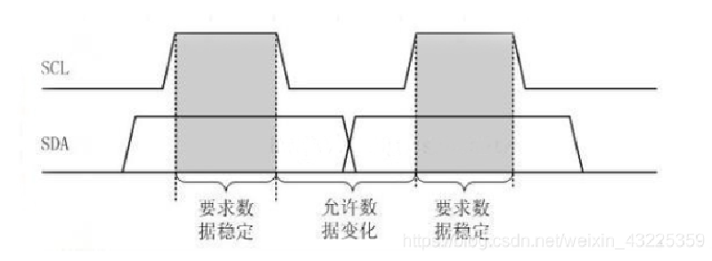
Specific requirements: when SCL is high level, SDA data line data is required to be stable, and when SCL is low level, SDA data line data can be changed.
SDA data transfers one bit of data in each clock cycle of SCL. The transmission of data bits is edge triggered
It can be summarized as follows
The data is ready before the rising edge of SCL. And must stabilize before the falling edge
IIC communication - read and write data (IIC protocol layer)
IIC protocol defines the start and stop signals, data validity, response, arbitration, clock synchronization and address broadcasting of communication.
① The master writes data to the slave
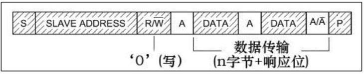
s: Start, start signal
p: Stop, stop signal
Slave address: slave address. After the start signal ends, the host starts broadcasting the address signal of the slave. Before broadcasting, each slave is in the "standby" state. Since each slave address is unique, only the address broadcast by the host corresponds to a slave, one slave will respond, and others will not respond. (it can be understood as the teacher's roll call in class 😄) The slave address can be 7 bits or 10 bits
R/w: read / write data
A: ACK, reply signal. When the data is written, the host can continue to write data only after the slave response signal is generated.
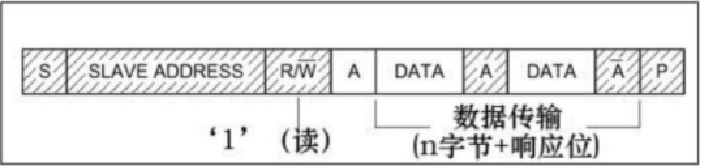
② Read data from host to slave
③ Communication between master and slave, communication composite format
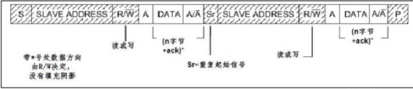
The main difference between the composite format and the previous one is that there are two start signals in the transmission process.
During the first transmission, the host passes slave_ After address finds the slave device, it sends a section of "data", which is usually used to represent the internal register or memory address of the slave device;
In the second transmission, the contents of the address are read or written. (same as before)
To sum up, the first communication is to tell the slave to read and write the address, and the second is to read and write the actual content.
Software simulates IIC timing (start, stop, screen clearing, display)
oled.c code
#include "stm32f10x.h"
#include "oled.h"
#include "oledfont.h"
#include "delay.h" 		// system timer

static void OLED_GPIO_Init(void)
{

	 GPIO_InitTypeDef   	oled_GPIOstruct;		//oled pin initialization
	 RCC_APB2PeriphClockCmd( RCC_APB2Periph_GPIOB, ENABLE );
     //PB0 ->SCL    PB1 ->SDA
	 oled_GPIOstruct.GPIO_Mode = GPIO_Mode_Out_OD;	//Open drain output
	 oled_GPIOstruct.GPIO_Pin =GPIO_Pin_0 | GPIO_Pin_1 ;
	 oled_GPIOstruct.GPIO_Speed = GPIO_Speed_50MHz;
	 GPIO_Init( GPIOB, &oled_GPIOstruct);

	OLED_SCLK_Set();//Defined in the header file below
	OLED_SDIN_Set();//Pull up the clock line and data line to make them idle
}

//Analog IIC start signal
static void OLED_IIC_Start(void)
{
	OLED_SCLK_Set();
	OLED_SDIN_Set();
	delay_us(1);
	OLED_SDIN_ReSet();	//The data line is pulled low to produce a falling edge
	delay_us(1);
	OLED_SCLK_ReSet();	//After the clock line and the data line generate a falling edge, maintain the high level for a period of time, pull it down, and the simulation of the starting signal is completed
	delay_us(1);
}

//IIC analog stop signal
static void OLED_IIC_Stop(void)
{
	OLED_SDIN_ReSet();
	OLED_SCLK_ReSet();
	delay_us(1);
	OLED_SCLK_Set();	//The clock line is pulled up first
	delay_us(1);
	OLED_SDIN_Set();	//The data line is pulled high to generate a rising edge, so far the simulation of the stop signal is completed
	delay_us(1);
}

//IIC analog read slave response signal
static unsigned char IIC_Wait_Ack(void)
{
	unsigned char Ask;
	OLED_SCLK_ReSet();		//Clock line pulled low
	delay_us(1);
	OLED_SDIN_Set();		//Data cable pull up
	delay_us(1);
	OLED_SCLK_Set();		//Clock line pull up
    //The reply signal generates a falling edge before the clock line is pulled high, and ensures a low level when the clock line is pulled high
	if(OLED_READ_SDIN())	//The read data line level is high
	{
		ack = IIC_NO_Ask;	//The corresponding response signal is a non response signal
	}
	else
	{
		ack = IIC_Ask;		//The corresponding signal is the response signal
	}
	OLED_SCLK_ReSet();		//After receiving the response signal, the clock line is pulled down
	delay_us(1);
	return ack;
}

//Write one bit data
static void Write_IIC_Byte(unsigned char IIC_Byte)
{
	unsigned char i=0;
	for(i=0;i<8;i++)	         //Write per cycle
	{
		OLED_SCLK_ReSet();		//Pull down the clock line so that the subsequent data can be changed
		delay_us(1);
		if(IIC_Byte & 0x80)		//1000 0000 reads the eighth bit
			OLED_SDIN_Set();	//The highest bit is 1. Set the data line high (transmit data through high and low levels)
		else
			OLED_SDIN_ReSet(); 	//The highest bit is 0. Pull the data cable down
		IIC_Byte <<= 1; 		//The data is shifted to the left by 1 bit, and the second highest bit becomes the highest bit
		delay_us(1);
		OLED_SCLK_Set();		//After transmitting and confirming one bit of data, the clock line is pulled up to read this bit of data
		delay_us(1);
	}

	    OLED_SCLK_ReSet();		//After all 8-bit data are read, the clock line is pulled down
		delay_us(1);
		while(IIC_Wait_Ack());	//Wait for the reply signal to pass!
}

//IIC write command
static void Write_IIC_Command(unsigned char IIC_Command)
{
	OLED_IIC_Start();
	Write_IIC_Byte(0x78);		//First sending slave address
	Write_IIC_Byte(0x00);		//Second send command address
	Write_IIC_Byte(IIC_Command);//Write specified command
	OLED_IIC_Stop();			//Send stop signal
}

//IIC write data
static void Write_IIC_Data(unsigned char IIC_Data)
{
	OLED_IIC_Start();
	Write_IIC_Byte(0x78);		//First sending slave address
	Write_IIC_Byte(0x40);		//Second sending data address
	Write_IIC_Byte(IIC_Data);	//Write specified command
	OLED_IIC_Stop();			//Send stop signal
}

//Write a byte to OLED
void OLED_Write_Byte(unsigned char dat,unsigned char cmd)
{
	if(cmd)
	{
		Write_IIC_Data(dat);	//Write data
	}
	else
	{
		Write_IIC_Command(dat);//Write command
	}
}

//Set OLED start coordinates
void SetPoint(unsigned char x,unsigned char y)
{	//Column x
    //Address of the start page of y page 0-7
	OLED_Write_Byte(0xb0+y,OLED_CMD);		//Write page address write command
	OLED_Write_Byte((x&0xf0>>4),OLED_CMD);	//Write command for the upper four digits of column address
	OLED_Write_Byte(x&0x0f|0x10,OLED_CMD);	//Write command in the lower four digits of column address
}
//Turn on screen display
void OLED_Display()
{
	OLED_Write_Byte(0x8D,OLED_CMD);	//Set charge pump
	OLED_Write_Byte(0xAF,OLED_CMD);//Open screen
	OLED_Write_Byte(0x14,OLED_CMD);//Turn on the charge pump
}
//Turn off screen display
void OLED_OFF()
{
	OLED_Write_Byte(0x8D,OLED_CMD);	//Set charge pump
	OLED_Write_Byte(0xAE,OLED_CMD);//Close screen
	OLED_Write_Byte(0x10,OLED_CMD);//Turn off the charge pump
}
//Screen clearing operation
void OLED_Clear()
{
	unsigned char i,n;
	for(i=0;i<8;i++)//There are 8 pages in total
	{
		OLED_Write_Byte(0xb0+i,OLED_CMD);//Write from page 0-7
		OLED_Write_Byte(0x00,OLED_CMD);	//Column low address
		OLED_Write_Byte(0x10,OLED_CMD);	//Column height address
		for(n=0;n<128;n++)
		{
			OLED_Write_Byte(0,OLED_Data);//Write data 0 to all 128 * 64 pixels
		}
	}
}
//OLED display character function
void OLED_Showcharactor(unsigned char x,unsigned char y,unsigned char chr)
{	//The input parameters X and Y represent columns and pages respectively, and chr represents characters
	unsigned char c=0,i=0;
	c = chr - ' ';		//Here, the offset of the obtained character can be known by combining the word library and ASCII code
	if(x>MAX_Column)	//If the column exceeds the maximum length, start from column 0 on the next two pages
	{
		x = 0;
		y = y+2;	  	//The character size is 8x16, so the page needs to add two lines at one time
	}
	if(SIZE == 16)		//If the character size is 16 = 8 * 16
	{
		OLED_SetPoint(x,y);	//Set OLED start coordinates
		for(i=0;i<8;i++)
			OLED_Write_Byte(F8X16[c*16+i],OLED_Data);//Find the number of digits in the array of character C and draw the first column first
		OLED_SetPoint(x,y+1);
		for(i=8;i<16;i++)//Display 8 first and then 8
			OLED_Write_Byte(F8X16[c*16+i],OLED_Data);
	}
	else						// 6*8
	{
		OLED_SetPoint(x,y);
		for(i=0;i<6;i++)
			OLED_Write_Byte(F6x8[c][i],OLED_Data);
	}
}

//Display string function
void OLED_ShowString(unsigned char x,unsigned char y,unsigned char *chr)
{
	unsigned char j = 0;
	while(chr[j]!='\0')	//Loop through the string to determine whether it is the last character
	{
		OLED_Showcharactor(x,y,chr[j]);	//Call the previous show single character function
		x+=8;//The number of columns + 8. One character accounts for 8
		if(x>=128)
		{
			x=0;//The first column shows
			y+=2;//Page change
		}
		j++;
	}
}
//Calculate m^n power function
unsigned int OLED_Pow(unsigned char m,unsigned char n)
{
	unsigned int result = 1;
	while(n--)
		result*=m;
	return result;
}
//Display numeric function
void OLED_ShowNum(unsigned char x,unsigned char y,unsigned int num,unsigned char len,unsigned char size)
{//Pass in parameters x,y columns and pages; num corresponds to the number; len number of digits; Size font size
	unsigned char t,temp;
	unsigned char enshow = 0;	//Flag indicating whether the first number is 0
	for(t=0;t<len;t++)
	{
		temp = (num/OLED_Pow(10,len-t-1))%10;	//Get data from low order
		if(enshow==0&&t<(len-1))//Whether enshow is the first number T < (len-1) determines whether it is the last digit
		{	//Judge whether the current number is 0. If it is 0, it needs to be displayed additionally
			if(temp==0)
			{	//If it is 0, it will display 0, and then continue to execute the function
				OLED_Showcharactor(x+(size/2)*t,y,' ');//Show 0
				continue;	//Jump out of the current cycle to avoid repeated display
			}
			else
				enshow=1;
		}
		OLED_Showcharactor(x+(size/2)*t,y,temp+'0');//Show last bit
	}
}

//Display Chinese character function
void OLED_ShowChinese(unsigned char x,unsigned char y,unsigned char no)
{//Parameter x,y columns and pages; 	 no stands for the position of a Chinese character in the Chinese character library
	unsigned char t,adder=0;
	OLED_SetPoint(x,y);
	for(t=0;t<16;t++)
	{
		OLED_Write_Byte(Hzk[2*no][t],OLED_Data);//Draw no the point in column 16 on the first page of the array position
		adder+=1;
	}
	OLED_SetPoint(x,y+1);	//The Chinese characters here are displayed in 8x16
		for(t=0;t<16;t++)
	{                      //A word is two 16 bits
		OLED_Write_Byte(Hzk[2*no+1][t],OLED_Data);//Draw no the point in column 16 on the second page of the array position
		adder+=1;
	}
}

void OLED_Init(void)
{
	OLED_GPIO_Init();

	delay_ms(200);

	OLED_Write_Byte(0xAE,OLED_CMD);

	OLED_Write_Byte(0x00,OLED_CMD);
	OLED_Write_Byte(0x10,OLED_CMD);
	OLED_Write_Byte(0x40,OLED_CMD);
	OLED_Write_Byte(0xB0,OLED_CMD);

	OLED_Write_Byte(0x81,OLED_CMD);
	OLED_Write_Byte(0xFF,OLED_CMD);

	OLED_Write_Byte(0xA1,OLED_CMD);
	OLED_Write_Byte(0xA6,OLED_CMD);

	OLED_Write_Byte(0xA8,OLED_CMD);
	OLED_Write_Byte(0x3F,OLED_CMD);

	OLED_Write_Byte(0xC8,OLED_CMD);

	OLED_Write_Byte(0xD3,OLED_CMD);
	OLED_Write_Byte(0x00,OLED_CMD);

	OLED_Write_Byte(0xD5,OLED_CMD);
	OLED_Write_Byte(0x80,OLED_CMD);

	OLED_Write_Byte(0xD9,OLED_CMD);
	OLED_Write_Byte(0xF1,OLED_CMD);

	OLED_Write_Byte(0xDA,OLED_CMD);
	OLED_Write_Byte(0x12,OLED_CMD);

	OLED_Write_Byte(0xDB,OLED_CMD);
	OLED_Write_Byte(0x40,OLED_CMD);

	OLED_Write_Byte(0x8D,OLED_CMD);
	OLED_Write_Byte(0x14,OLED_CMD);

	OLED_Write_Byte(0xAF,OLED_CMD);
	OLED_Clear();
	OLED_SetPoint(0,0);
}
oled.h file
#ifndef _OLED_H_
#define _OLED_H_

#include "stm32f10x.h"


#define OLED_SCLK_Set()      GPIO_SetBits(GPIOB,GPIO_Pin_0)
#define OLED_SCLK_ReSet()  	 GPIO_ResetBits(GPIOB, GPIO_Pin_0)
#define OLED_SDIN_Set()		 GPIO_SetBits(GPIOB,GPIO_Pin_1)
#define OLED_SDIN_ReSet()    GPIO_ResetBits(GPIOB,GPIO_Pin_1)
#define OLED_READ_SDIN()     GPIO_ReadInputDataBit(GPIOB, GPIO_Pin_1)


#define IIC_Ask     0
#define IIC_NO_Ask  1

#define OLED_CMD	0
#define OLED_Data   1
#define MAX_Column  128
#define SIZE		16

static void OLED_GPIO_Init(void);
static void OLED_IIC_Start(void);
static void OLED_IIC_Stop(void);
static unsigned char IIC_Wait_Ack(void);
static void Write_IIC_Byte(unsigned char IIC_Byte);
static void Write_IIC_Command(unsigned char IIC_Command);
static void Write_IIC_Data(unsigned char IIC_Data);
void OLED_Write_Byte(unsigned char dat,unsigned char cmd);
void OLED_SetPoint(unsigned char x,unsigned char y);
void OLED_Display(void);
void OLED_OFF(void)	;
void OLED_Clear(void);
void OLED_Fill(void);
void OLED_Showcharactor(unsigned char x,unsigned char y,unsigned char chr);
void OLED_Init(void);
void OLED_ShowString(unsigned char x,unsigned char y,unsigned char *chr);
unsigned int OLED_Pow(unsigned char m,unsigned char n);
void OLED_ShowNum(unsigned char x,unsigned char y,unsigned int num,unsigned char len,unsigned char size);
void OLED_ShowChinese(unsigned char x,unsigned char y,unsigned char no);
#endif
DHT11 temperature and humidity module
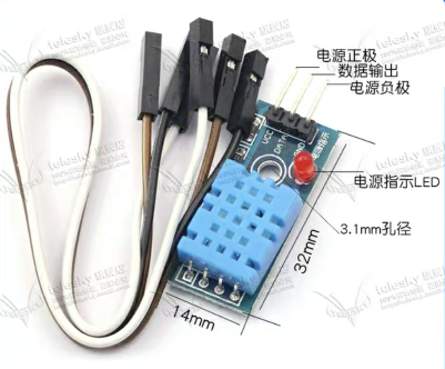
Supply voltage: 3.3 - 5.5V DC
The output is a single bus digital signal
Temperature measurement range: 0-50 degrees (accuracy: plus or minus 2 degrees, resolution: 1 degree)
The humidity measurement range is 20-90%RH (accuracy is plus or minus 5% and resolution is 1%)
Principle:
Using the single bus two-way serial communication protocol, each acquisition should be initiated by the single chip microcomputer, and then DHT11 will send a response to the single chip microcomputer and start transmitting 40 bit data frames, with the high bit in front. The data format is 40 frames (40bit).
- Humidity integer part + humidity decimal part 8bit + 8bit
- Temperature integer part + temperature decimal part 8bit + 8bit
- Check bit part 8bit
For data verification, add up the integer and decimal parts of humidity and temperature to judge whether they are equal to the verification bit part. If they are equal, take out the data; No, the humidity fractional part and temperature fractional part of the data are retrieved. The MCU defaults to 0, that is, the check digit will only judge the sum of the integer parts of the two
E.g. humidity 0101 0011 + 0000
Temperature 0011 0010 + 0000
Check bit 1000 0101
At this time, the sum of the integer parts of humidity and temperature is exactly equal to the of the check bit, so this group of data meets the requirements.
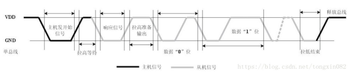
Timing process of temperature and humidity sensor
-
Bus idle state high level
-
The host pulls down the bus and waits for a response from DHT11 (the host sends a start signal)
-
After the slave (DHT11 module) receives the host start signal, wait for the host start signal to end. This process requires more than 18ms to ensure that DHT11 detects the start signal
-
DHT11 sends 80us low level response signal
-
After the host sends the start signal, read the response signal of DHT11 after a delay of 20-40us
-
After the host sends the start signal, it can switch to the input mode or connect the pull-up resistor to set the high level
Software IIC displays temperature and humidity
DHT11.c Documents
#include "stm32f10x.h"

#include "DHT11.h"
#include "stdio.h"
#include "delay.h"

/*Single bus, bidirectional serial output protocol, so the corresponding port input and output is configured*/
uint16_t Rxbuff[5];

void DHT11_GPIO_Init_IN(void)
{
	GPIO_InitTypeDef DHT11_GPIOinstruct;
//Pb11 - > DHT11 module data input port
	RCC_APB2PeriphClockCmd( RCC_APB2Periph_GPIOB, ENABLE);
	DHT11_GPIOinstruct.GPIO_Mode = GPIO_Mode_IPD;	//Drop down input
	DHT11_GPIOinstruct.GPIO_Pin = GPIO_Pin_11;
	DHT11_GPIOinstruct.GPIO_Speed = GPIO_Speed_50MHz;

	GPIO_Init(GPIOB, &DHT11_GPIOinstruct);
}
void DHT11_GPIO_Init_OUT(void)
{
	GPIO_InitTypeDef DHT11_GPIOinstruct;
//Pb11 - > DHT11 module data output port
	RCC_APB2PeriphClockCmd( RCC_APB2Periph_GPIOB, ENABLE);
	DHT11_GPIOinstruct.GPIO_Mode = GPIO_Mode_Out_PP;
	DHT11_GPIOinstruct.GPIO_Pin = GPIO_Pin_11;
	DHT11_GPIOinstruct.GPIO_Speed = GPIO_Speed_50MHz;

	 GPIO_Init(GPIOB, &DHT11_GPIOinstruct);
}
//Temperature and humidity module response signal
static uint8_t DHT11_Back()
{
	uint8_t i = 200;
	while(read_data && i--);	//Wait for the low level to arrive
	i=200;						//Low level delay (80us)
	while(!read_data && i--);	//Wait for the high level to arrive
	return 0;
}
//Start signal
void DHT11_Start()
{
	data0;		//Set low
	delay_ms(20);
	data1;		//Set high
	delay_us(10);
	DHT11_GPIO_Init_IN();
	while(DHT11_Back());
}
//DHT11 module read data function
void DHT11_ReceptionBuff()
{
	uint8_t y =1;
	uint16_t i;
	uint8_t x;
	for(x=0;x<5;x++)
	{
		i = 0;
		for(y=1;y<9;y++)
		{
			while(read_data)
			{
				__nop();
			}
			delay_us(40);
			while(!read_data)
			{
				__nop();
			}
		i = i<<1;
		delay_us(30);
			if(read_data)
			{
				i|=1;
			}
			while(read_data);
		 }
		Rxbuff[x] = i;
 }
}
DHT11.h file
#ifndef _DHT11_H_
#define _DHT11_H_
#include "stm32f10x.h"
#define data1 GPIO_SetBits(GPIOB,  GPIO_Pin_11)
#define data0 GPIO_ResetBits(GPIOB,  GPIO_Pin_11)
#define read_data GPIO_ReadInputDataBit(GPIOB,  GPIO_Pin_11)
void DHT11_GPIO_Init_IN(void);
void DHT11_GPIO_Init_OUT(void);
void DHT11_Start(void);
void DHT11_ReceptionBuff(void);
void DHT11_UpdataData(void);
extern uint16_t Rxbuff[5];
#endif
main function
#include "stm32f10x.h"
#include "main.h"
#include "oled.h"
#include "delay.h"
#include "sys.h"
#include "DHT11.h"
int  main()
{
 initSysTick();

	delay_ms(1000);
	OLED_Init();
	OLED_Clear();
	delay_ms(1000);
	//Let the OLED display the following words in the font
	OLED_ShowChinese(0,2,6);		//When all are displayed on the second page
	OLED_ShowChinese(16,2,7);		//front
	OLED_ShowChinese(32,2,8);		//temperature
	OLED_ShowChinese(48,2,9);		//degree
	OLED_ShowChinese(66,2,10);		//:
	OLED_ShowChinese(90,2,15);		//.
	OLED_ShowChinese(112,2,11);		//℃
	//This is from the font file oledfont h
	OLED_ShowChinese(0,5,6);		//When
	OLED_ShowChinese(16,5,7);		//front
	OLED_ShowChinese(32,5,12);		//wet
	OLED_ShowChinese(48,5,9);		//degree
	OLED_ShowChinese(66,5,10);		//:
	OLED_ShowChinese(90,5,15);		//.
	OLED_ShowChinese(112,5,13);		//%
	while(1)
	{
		uint16_t i;
		uint8_t  Tempture ;
		uint8_t  Wet ;
		uint8_t  xiaoshu ;
		DHT11_UpdataData();

		i = Rxbuff[0] + Rxbuff[1] + Rxbuff[2] + Rxbuff[3];
			if(Rxbuff[4]==i)		//check
			{
				Tempture = Rxbuff[2];		//Temperature integer
				Wet = Rxbuff[0];			//Humidity integer
				xiaoshu = Rxbuff[3];		//Decimal part (same for both)

				OLED_ShowNum(74,2,Tempture/10,3,3);
				OLED_ShowNum(82,2,Tempture%10,3,3);
			    OLED_ShowNum(98,2,xiaoshu,3,3);
				OLED_ShowNum(88,5,Wet/10,3,3);
				OLED_ShowNum(98,5,xiaoshu%10,3,3);
			}
		delay_ms(2000);
	}
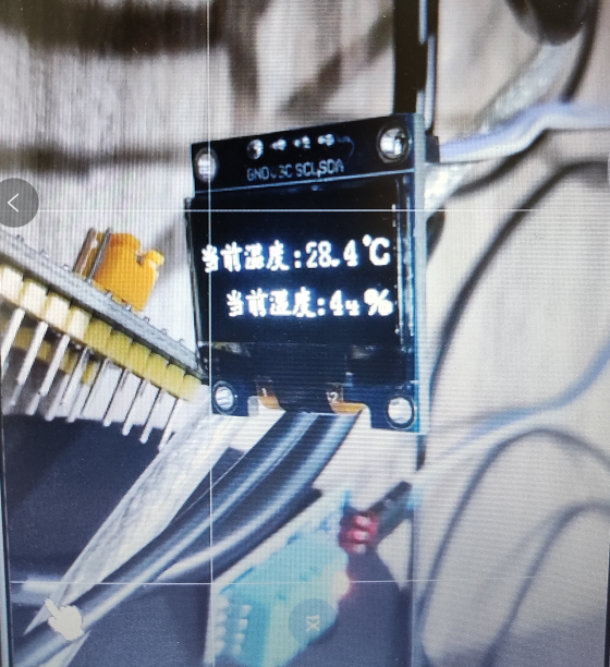
Display effect