1) Experimental platform: ZYNQ development board of punctual atomic navigator
2) Platform purchase address: https://item.taobao.com/item.htm?&id=606160108761
3) Full set of experimental source code + manual + video download address: http://www.openedv.com/thread-301505-1-1.html
4) Students interested in punctual atomic FPGA can add group discussion: 994244016
5) pay attention to the official account of the dot atom and get updated information.
Chapter 11 touch key control LED lamp experiment
With the continuous development of electronic technology, the application scenarios of keys are more and more extensive. Touch keys are superior to traditional mechanical keys in stability, service life and anti-interference ability. They are widely used in remote controls, portable electronic equipment, corridor light switches, control panels of various household appliances and so on. This chapter will introduce the control method of touch key, and use the touch key on the development board to control the lighting of led.
This chapter is divided into the following chapters:
1.1 introduction to touch keys
1.2 experimental tasks
1.3 hardware design
1.4 program design
1.5 download verification
1.1 introduction to touch keys
Touch keys can be divided into four categories: resistance, capacitance, infrared induction and surface acoustic wave. According to their different properties, each touch key has its appropriate field of use.
The resistive touch button is printed by multiple conductive films according to the position of the button, but the current utilization rate is low due to poor durability and complex maintenance; The infrared inductive touch key can identify the key position through infrared scanning, which is generally used in harsh environment; The surface acoustic wave touch button uses acoustic wave scanning to identify whether it is pressed or not. It has a long service life and is more suitable for POS machines and vending machines in public places.
Capacitive touch button: the birth of this button is mainly to overcome the shortage of poor durability of resistive button. The capacitive touch button adopts the capacitance as the evaluation standard, and its sensing area can penetrate the insulating shell (glass, plastic, etc.) by more than 20mm. Its sensitivity and reliability will not change due to the change of environmental conditions or long-term use. It has the advantages of waterproof, strong anti-interference ability, wide temperature range and long service life. It is the most widely used and fastest developing touch key in modern times.
Next, let's specifically understand the structure and working principle of capacitive touch buttons.
The capacitive touch key is mainly composed of key IC part and capacitance part. The key IC part is mainly provided by the component supplier to convert the change of capacitance into electrical signal. The capacitive part refers to the capacitive environment of touching the key, which is composed of capacitive plate, ground, isolation area, etc.
There is an inductive capacitance between any two conductive objects. When the surrounding environment remains unchanged, the inductive capacitance value is fixed. As shown in the figure below, when the finger touches the touch key, parasitic capacitance is generated between the key and the finger, increasing the total capacitance of the key.

Figure 7.5.13.1 schematic diagram of parasitic capacitance of touch key
The change of capacitance before and after pressing the touch key is shown in the figure below. The capacitive touch key IC will output a valid signal indicating that the key is pressed after detecting the change of the induced capacitance value of the key and exceeding a certain threshold.
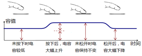
Figure 7.5.13.2 schematic diagram of capacitance change during touch
1.2 experimental tasks
The experimental task of this section is to use the touch key to control the LED light on and off. After the development board is powered on, the LED is on, and after the finger touch, the LED is off; When touched again, the LED turns on.
1.3 hardware design
The schematic diagram of the touch key part on the navigator development board is shown in figure 7.5.13.1. TPAD is the output pin of the chip, which is connected to the IO port of ZYNQ.

Figure 7.5.13.1 schematic diagram of touch key circuit
The touch IC model used on the development board is AR101 (or JL223B, which is fully compatible with AR101). It can select different working modes through OP1 and OP2 pins: when OP1 is pulled low, the output signal of OUT pin is valid at high level; When OP1 is pulled high, the low level of OUT output signal is valid.
When OP2 is pulled down, the touch IC works in the synchronization mode (similar to the non self-locking touch key), that is, the effective level is output when touching, and there is no effective level after releasing; When OP2 is pulled up, the touch IC works in the hold mode (similar to the self-locking key), that is, the effective level is output after the touch operation is detected. After it is released, the output level remains unchanged. When the touch operation is detected again, the output level changes and continues to be maintained.
In figure 7.5.13.1, pins OP1 and OP2 of touch IC are pulled low. Therefore, when the finger presses the touch key, the TOUT pin outputs high level and outputs low level after releasing.
In this experiment, the pin distribution of the system clock, reset key, touch key and LED lamp is shown in the table below. The clock crystal oscillator is located on the core board, and the reset key, touch key and LED are located on the base plate.
Table 11.3.1 pin distribution diagram of touch key control LED
Signal name direction pin port description level standard
sys_clk input U18 system clock, 50M LVCMOS33
sys_rst_n input N16 system reset, low effective LVCMOS33
touch_key input F16 touch key signal LVCMOS33
led output H15 LED LVCMOS33
The corresponding XDC constraint statements are as follows:
#IO constraints
set_property -dict {PACKAGE_PIN U18 IOSTANDARD LVCMOS33} [get_ports sys_clk]
set_property -dict {PACKAGE_PIN N16 IOSTANDARD LVCMOS33} [get_ports sys_rst_n]
set_property -dict {PACKAGE_PIN F16 IOSTANDARD LVCMOS33} [get_ports touch_key]
set_property -dict {PACKAGE_PIN H15 IOSTANDARD LVCMOS33} [get_ports led]
1.4 program design
The module port and signal connection of this design are shown in the figure below. By capturing the rising edge of the touch key port, a clock cycle pulse signal is obtained to control the on and off of the LED lamp.
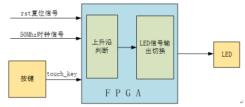
Figure 7.5.13.1 module port and signal connection diagram
Touch key control led code is as follows:
1  module touch_led(
2      //input
3      input        sys_clk,      //Clock signal 50Mhz
4      input        sys_rst_n,    //Reset signal
5      input        touch_key,    //Touch key
6
7      //output
8      output  reg  led           //LED light
9  );
10
11 //reg define
12 reg    touch_key_d0;
13 reg    touch_key_d1;
14
15 //wire define
16 wire   touch_en;
17
18 //*****************************************************
19 //**                    main code
20 //*****************************************************
21
22 //Capture the rising edge of the touch key port to obtain a clock cycle pulse signal
23 assign  touch_en = (~touch_key_d1) & touch_key_d0;
24
25 //Delay the data of the touch key port by two clock cycles
26 always @ (posedge sys_clk or negedge sys_rst_n) begin
27     if(!sys_rst_n) begin
28         touch_key_d0 <= 1'b0;
29         touch_key_d1 <= 1'b0;
30     end
31     else begin
32         touch_key_d0 <= touch_key;
33         touch_key_d1 <= touch_key_d0;
34     end
35 end
36
37 //Switch the led state according to the pulse signal on the rising edge of the touch key
38 always @ (posedge sys_clk or negedge sys_rst_n) begin
39     if (!sys_rst_n)
40         led <= 1'b1;       //By default, the LED is on
41     else begin
42         if (touch_en)
43             led <= ~led;
44     end
45 end
46
47 endmodule
Lines 22 to 35 in the program are a classic edge detection circuit by detecting touch_ The rising edge of key is used to capture the signal of key press. Once the key press is detected, a clock cycle pulse touch is output_ en. Whenever a touch is detected_ The pulse signal of en and led are reversed once.
In order to verify our program, we simulated the code in Vivado.
The Testbench module code is as follows:
1  `timescale 1ns / 1ps
2
3  module tb_touch_led();
4
5  //reg define
6  reg     sys_clk;
7  reg     sys_rst_n;
8  reg     touch_key;
9
10 //wire define
11 wire          led ;
12
13 always #10 sys_clk = ~sys_clk;
14
15 initial begin
16     sys_clk = 1'b0;
17     sys_rst_n = 1'b0;
18     touch_key = 0;
19     #200
20     sys_rst_n = 1'b1;
21     //touch_key signal change
22     #40  touch_ key = 1'b1 ;  // Press the touch button after 40ns
23     #200 touch_key = 1'b0 ;  //200ns touch button lift
24     #40  touch_ key = 1'b1 ;  // Press the touch button after 40ns
25     #200 touch_key = 1'b0 ;  //200ns touch button lift
26     #40  touch_ key = 1'b1 ;  // Press the touch button after 40ns
27     #200 touch_key = 1'b0 ;  //200ns touch button lift
28     #40  touch_ key = 1'b1 ;  // Press the touch button after 40ns
29     #200 touch_key = 1'b0 ;  //200ns touch button lift
30 end
31
32 touch_led  u_touch_led(
33     .sys_clk   (sys_clk),
34     .sys_rst_n (sys_rst_n),
35     .touch_key (touch_key),
36     .led       (led)
37 );
38
39 endmodule
The waveform obtained by simulation is shown in figure 7.5.13.2. As can be seen from the figure, when touch_key signal changes from level to high level, touch_key_d0 and touch_key_d1 signal delay touch respectively_ Key one clock cycle and two clock cycles will touch_key_ Touch after the sum of d0 signal is reversed_ key_ D1 signal is combined to obtain a pulse signal (touch_en) of one clock cycle. When touch is detected_ When the en signal is high, the led signal is reversed, so as to realize the function of touching the key to control the led lamp.

Figure 7.5.13.2 simulation waveform
1.5 download verification
Compile the project and generate a bitstream bit file. Connect one end of the downloader to the computer and the other end to the JTAG download port on the development board. Connect the power cord and turn on the power switch of the development board.
Click "Open Hardware Manager" at the bottom of the "Flow Navigator" window on the left side of Vivado. At this time, Vivado software recognizes the downloader, click "Progam Device" in the "Hardware" window to download the Program, and select "Program" in the pop-up interface to download the Program.
After downloading the program, you can see the PL on the backplane_ LED0 is on. Touch the key once to see that the LED light goes out. Touch again to turn on the LED light. As shown in the figure below:
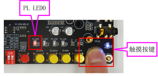
Fig. 7.5.13.1 experimental phenomenon of key controlled LED lamp