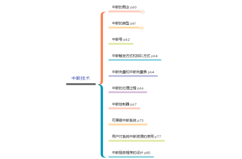
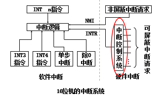
3. Interrupt technology
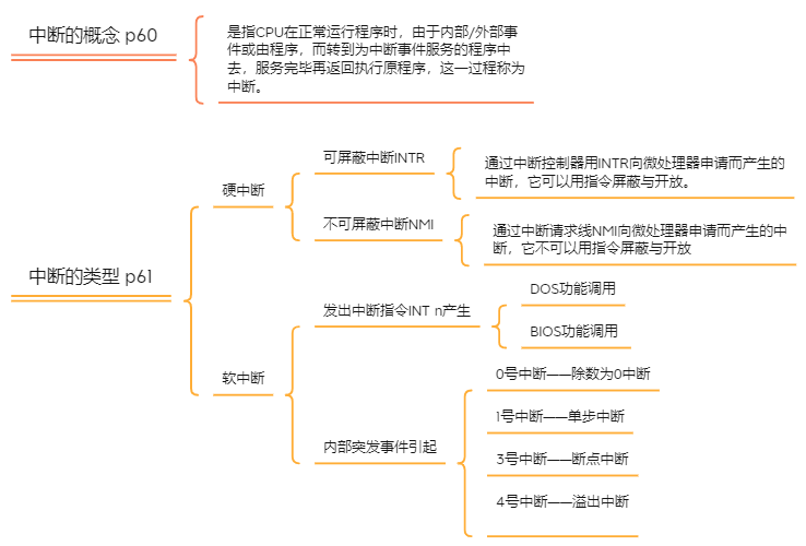
3.1 concept and type of interruption
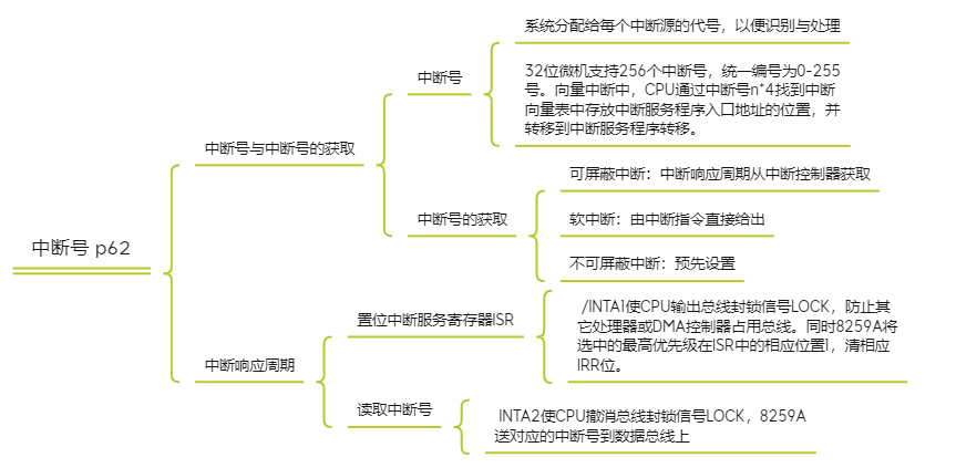
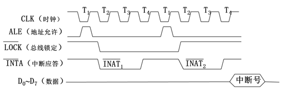
3.2 interrupt number
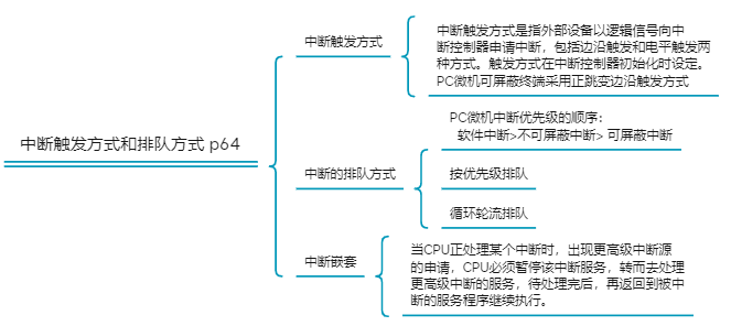
3.3 interrupt triggering mode and queuing mode
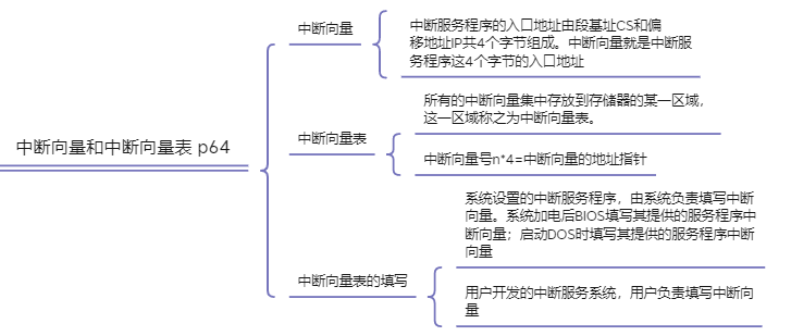
3.4 interrupt vector and interrupt vector table
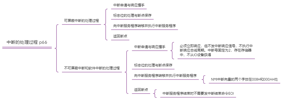
3.5 interrupt processing
3.6 interrupt controller

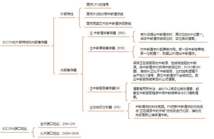
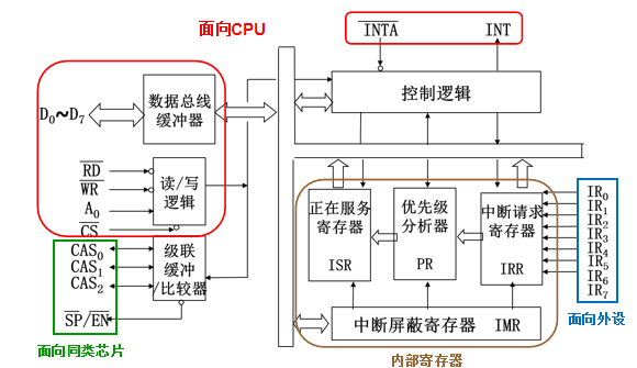
3.6.1 external characteristics, internal registers and port addresses of 82c59
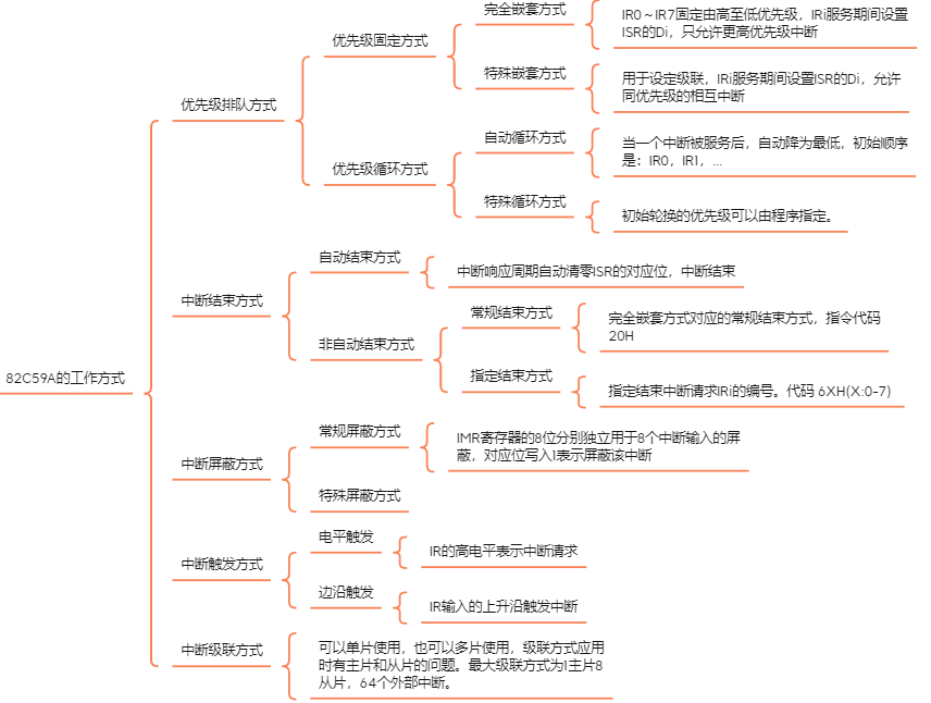
3.6.2 working mode of 82c59
3.6.3 programming command of 82c59
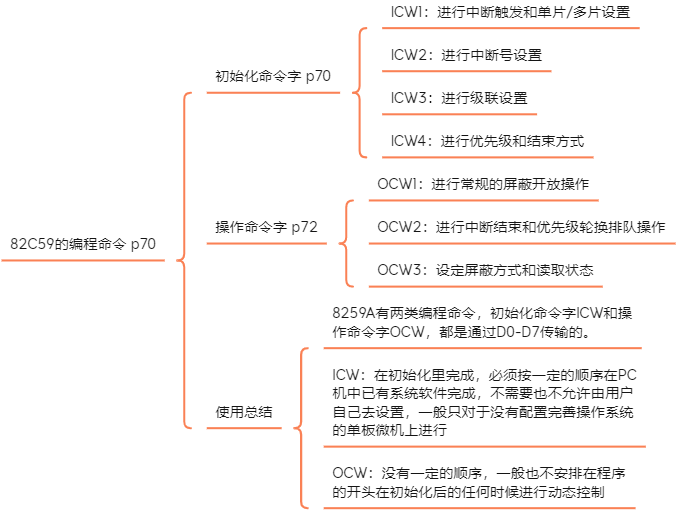
Initialization command sequence
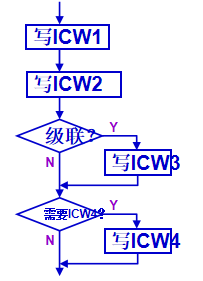
- ICW1 : A0=0
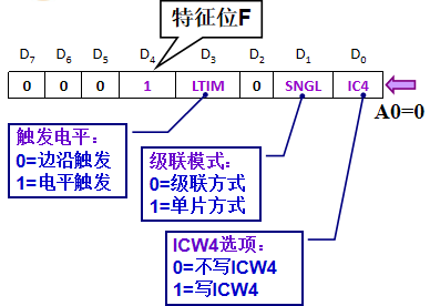
[example] if 259A adopts level trigger and is used by a single chip, ICW4 is required (D0=1 for more than 16 bit computers), then:
   MOV  AL,00011011B  ;ICW1 Content of
   OUT  20H,AL        ;write in ICW1 Port( A0=0)
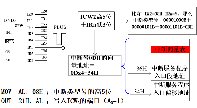
- ICW2 : A0=1
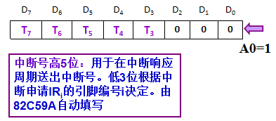
[example] hard disk interrupt number 0DH, i.e. 00001101B
- ICW3 : A0=1
- Main chip ICW3 setting:
1: A slave is connected to an IR of the master
0: the slave is not connected to an IR of the master
- Slave ICW3 settings
Slave chip ICW3: connect the INT pin of the slave chip to the IR pin of the master chip. No.: 000-111
[example] the request lines INT of slave A and slave B are connected to IR3 and IR6 of the master
- Main chip ICW3 setting:
	  Main slice ICW3=01001000B=48H
	     MOV AL,48H	;Main slice ICW3
		 OUT 21H,AL
    Slave piece A of ICW3=00000011B=03H
  	     MOV  AL,02H 	;Slave piece A of ICW3
       OUT  0A1H,AL
    Slave piece B of ICW3=00000110B=06H
  	     MOV  AL,06H 	;Slave piece A of ICW3
       OUT  0B1H,AL
- ICW4 : A0=1
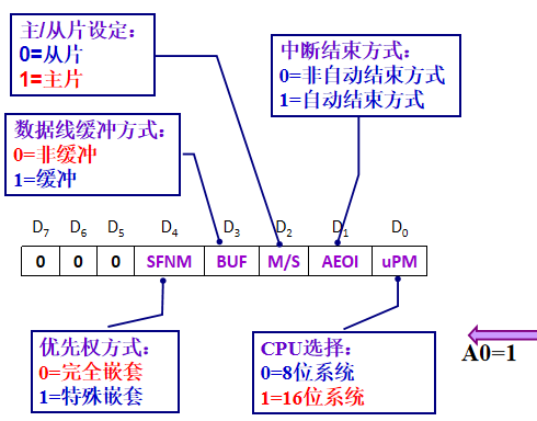
[example] the CPU of a computer is 80868259A, which is connected with the system bus by buffer. It is not automatically ended. Only one 259A is used, which is normally and completely nested.
ICW4=00001101B=0DH,Corresponding initialization segment:
MOV  AL,0DH
OUT  21H,AL
- OCW1: A0=1
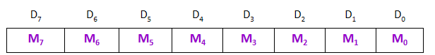
Used to set interrupt mask. Each bit corresponds to an interrupt input. 0 = open, 1 = shielded
[example] to open the interrupt source IR3, the rest are shielded: OCW1=11110111B=F7H. In the main program, write the corresponding program segment before interrupting:
		MOV  AL,0F7H
    	OUT  21H,AL   ;OCW1 Content delivery port
    	IN   AL,21H   ;Read back 21 H Contents of the port
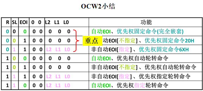
- OCW2 A0=0
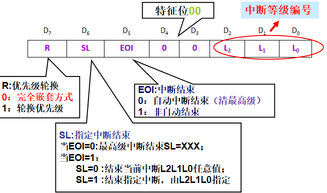
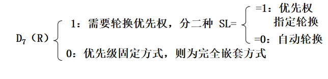
- Interrupt end control (D6 in OCW2 format)
When the initialization command ICW4 selects the non automatic end mode
When (D5=1), OCW2 is used to control the end of interrupt:
SL (D6) = 0 ends the current interrupt
OCW2=00100XXXB(L2-L0 = any value, common 000)
SL (D6) = 1, end the specified interrupt
OCW2=01100L2L1L0
If IR5 is terminated, for example:
OCW2=01100101B=65H - Interrupt priority queuing control
- Interrupt end control (D6 in OCW2 format)
[example] to specify the interrupt end method for IR3 interrupt, OCW2=01100011B=63H. In the interrupt service program, write the corresponding program segment before the interrupt return instruction IRET:
		MOV  AL,63H
    	OUT  20H,AL   ;write in OCW2 port(A0=0)
[example] for IR3 interrupt, do not specify interrupt end, OCW2=00100000B=20H. In the interrupt service program, write the corresponding program segment before the interrupt return instruction IRET
		MOV  AL,20H
    	OUT  20H,AL   ;write in OCW2 port(A0=0)
- OCW3 A0=0
Read the contents of IRR and ISR registers of 8259A
Set specific shielding mode
Query interrupt mode
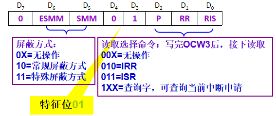
Read state operation
The 8259A has three internal registers IRR, ISR and IMR for the CPU to read the current content.
-
Methods of reading IRR and ISR
The CPU first specifies which register to read, and then issues the IN instruction to read the contents of ISR and IRR. When the 8259A is initialized, it automatically points to the read IRR register. -
Method of reading IMR
There is no need to issue the specified command first, just read the odd address port.[example] read the contents of ISR register
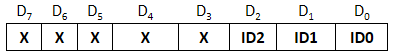
Specify the read register through OCW3. OCW3 is 00001011B, indicating that the ISR is to be read by the next RD. read the contents of the ISR register with the IN instructionMOV AL,0BH ;OCW3 Indicates reading ISR OUT 20H,AL ;20H by OCW3 Port address IN AL,20H ;read ISR register
[example] read the contents of IRR register
Specify the read register through OCW3. OCW3 is 00001010B, indicating that the IRR is to be read by the next RD; Read the contents of the IRR register with the IN instructionMOV AL,0AH ;OCW3 Indicates reading IRR OUT 20H,AL ;20H by OCW3 Port address IN AL,20H ;read IRR register
[example] read query word (whether query is interrupted - write ISR)
There are two steps: send the query command through OCW3. OCW3 is 00001100B, indicating that the query word is to be read by the next RD, and use the IN command to read the content of the query word.MOV AL,0CH ;use OCW3 Send query command OUT 20H,AL ;20H by OCW3 Port address IN AL,20H ;Read query word
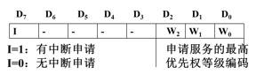
Format of query word:
8259A programming command usage summary
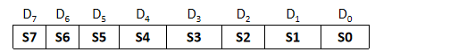
8259A has two types of programming commands, initialization command word ICW and operation command word OCW, which are transmitted through D0-D7.
ICW: completed in initialization, which must be in a certain order; The system software has been completed in the PC, and it is not required or allowed to be set by the user; Generally, it is only carried out on a single board microcomputer without a perfect operating system
OCW: there is no certain order, and it is generally not arranged at the beginning of the program; Perform dynamic control at any time after initialization
3.7 maskable interrupt system
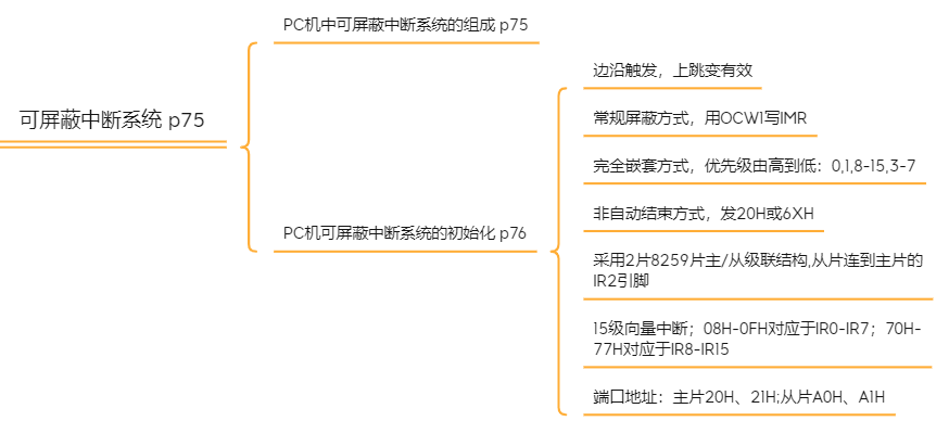
System initialization
Main slice:
    ICW1=11H;Edge trigger, multiple pieces, to ICW4
    ICW2=08H;5 digits higher than interrupt number
    ICW3=04H;Main slice IR2 From the film, D2=1
    ICW4=01H;Unbuffered, fully nested, 16 bit CPU
 Slave slice:
   ICW1=11H,ICW2=70H,ICW3=02H, ICW4=01H
Initialize master slice:
   INTA00 EQU 20H
   INTA01 EQU 21H
   MOV  AL,11H     ;ICW1
   OUT  INTA00H,AL
   JMP SHORT $+2    ;I/O Port delay requirements
   MOV  AL,08H     ;ICW2
   OUT  INTA01H,AL
   JMP SHORT $+2
   MOV  AL,04H     ;ICW3
   OUT  INTA01H,AL
   JMP SHORT $+2
   MOV  AL,01H     ;ICW4
   OUT  INTA01H,AL
Initialize slave slice:
   INTB00 EQU 0A0H
   INTB01 EQU 0A1H
   MOV  AL,11H     ;ICW1
   OUT  INTB00H,AL
   JMP SHORT $+2    ;I/O Port delay requirements
   MOV  AL,70H     ;ICW2
   OUT  INTB01H,AL
   JMP SHORT $+2
   MOV  AL,02H     ;ICW3
   OUT  INTB01H,AL
   JMP SHORT $+2
   MOV  AL,01H     ;ICW4
   OUT  INTB01H,AL
3.8 user's use of system interrupt resources

3.8.1 modify interrupt vector

; take N The original interrupt vector of interrupt No. and save it
CLI   ;Turn off interrupt when modifying interrupt vector!
MOV	AH,	35H
MOV	AL,	N
INT	21H
MOV	OLD_SEG,ES
MOV	OLD_OFF,BX

;set up N New interrupt vector
PUSH	DS
MOV	DX,	SEG INTRnew   ;Get the base address of the new interrupt vector segment
MOV	DS,	DX
MOV	DX,	OFFSET INTnew ;Get new interrupt vector offset address
MOV	AL,	N			       ;Interrupt type number is N
MOV	AH,	25H
INT	21H
POP		DS
IN	   AL,21H				;8259 Open interrupt
AND   AL,0FBH    ;1111 1011B  development IR2
OUT   21H,AL
STI

;Restore the original interrupt vector after sending data
MOV	DS, OLD_SEG
MOV	DX, OLD_OFF
MOV	AL,	N
MOV	AH,	25H
INT	21H
3.8.2 issue interrupt mask / open and interrupt end instructions
Write OCW1 in the main program to perform interrupt shielding and opening
Write OCW2 in the interrupt service program and send the interrupt end instruction EOI
NEW_INT PROC FAR
STI ;Open interrupt
;Register stack
;Service program body
;Xiang Zhu/From 82 C59A Send interrupt end command
  MOV	AL, 20H
  OUT 0A1H, AL
  OUT 20H,AL
;Register stack
;Interrupt return
  IRET
NEW_INT ENDP
to open up IRQ2 Interrupt method:
    IN AL,21H     ;read IMR register
    AND AL,0FBH   ;corresponding IRQ2 Location 0
    OUT 21H,AL
 close IRQ2 Interrupt method:
    IN AL,21H     ;read IMR register
    OR AL,04H     ;corresponding IRQ2 Location 1
    OUT 21H,AL