1, Basic storage unit
-
bit:
A digit in a binary number, which can be 0 or 1. It is the smallest unit of data in a computer.
-
Byte s:
The basic unit of data in a computer. Every 8 bits form a byte. All kinds of information need at least one byte to be stored and processed in the computer.
For example, an ASCII code is represented by one byte and a Chinese character is represented by two bytes.
-
Word:
Two bytes are called a word. The storage unit of Chinese characters is one word.
1 byte = 8-bit data
A Chinese character is a word, that is, two bytes, 16 bit data
2, Communication protocol
Communication mode - block diagram - reference link
(1) Parallel communication and serial communication
-
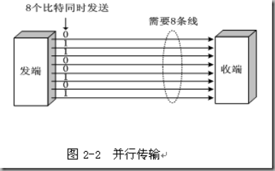
Parallel communication
8-bit data is transmitted in parallel. 8 lines are required to transmit an 8-bit data.
For example: SDIO, FSMC(16 bit) – all data bits are transmitted at the same time
-
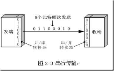
serial communication
8-bit data can be transmitted bit by bit with only one cable.
For example, USART, IIC and SPI are all serial methods - when sending data, they send data bit by bit
-
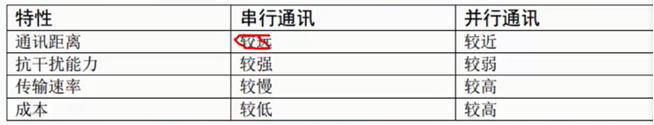
Characteristics of serial communication and parallel communication
(2) Three working modes
-
full duplex
There are two data lines, one for receiving data and the other for transmitting data. They do not interfere with each other and can send and receive data at the same time.
For example: usart (half duplex or full duplex communication), SPI (half duplex or full duplex communication)
-
Half duplex
There are two data lines, but you can't send data at the same time. You can send and receive data time-sharing
-
Simplex
Only one data line, only one-way communication (only one direction)
Example: IIC
(3) Send and receive data synchronously or asynchronously
-
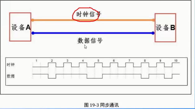
Synchronous communication
In the data synchronization mode, the clock signals of the two devices are the same (those with clock signals are synchronized).
In order to ensure the accuracy of data transmission during data transmission:
(1) When the clock is at high level, the data is valid
(2) The clock signal is invalid when the data is at low level
(3) High requirements for clock (if the clock has spikes or clutter, the data transmission is inaccurate)For example: SPI, IIC communication interface.
-
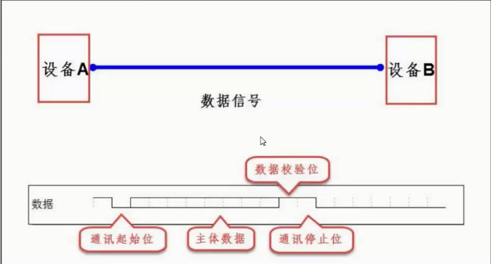
asynchronous communication
No clock signal: in order to ensure the accuracy of data transmission, some auxiliary identifiers are added
For example: UART (universal asynchronous transceiver), single bus.
-
Comparison of synchronous communication and asynchronous communication
(1) In synchronous communication, most of the content transmitted by data signal is effective data.
(2) In asynchronous communication, the transmitted data will contain various identifiers of frames.
(3) Therefore, the efficiency of synchronous communication is better, but the allowable error for clock is small, and the allowable error for clock is large for asynchronous communication.
(4) Communication rate
-
Bit rate: binary number transmitted per second unit: bit/s
IIC,SPI (synchronous communication, one data is transmitted under one clock and controlled by the clock)
-
Baud rate: number of symbols transmitted per second (serial port)
A binary bit represents a symbol (in special cases)
3, Serial communication protocol
The physical layer dictates whether we communicate with our mouth or limbs
The protocol layer stipulates whether we communicate in Chinese or English
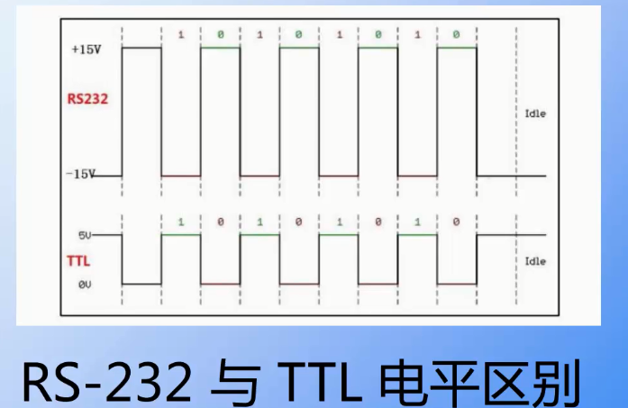
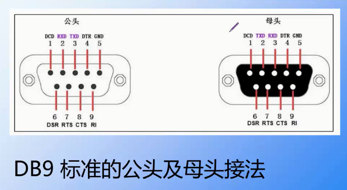
(1) RS232
1. RS232 and TTL are the difference in level
TTL level is directly from the single chip microcomputer (or chip): the high level is represented by 3.3V or 5v, and the low level is represented by 0
In RS232, 1 is represented by - 15V and 0 by + 15V. The logic is just the opposite, and the gap between low level and high level is very large
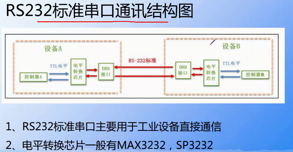
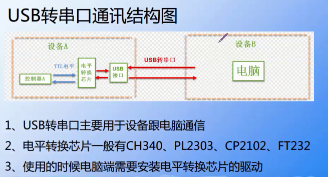
(2) USB to serial port (TTL standard)
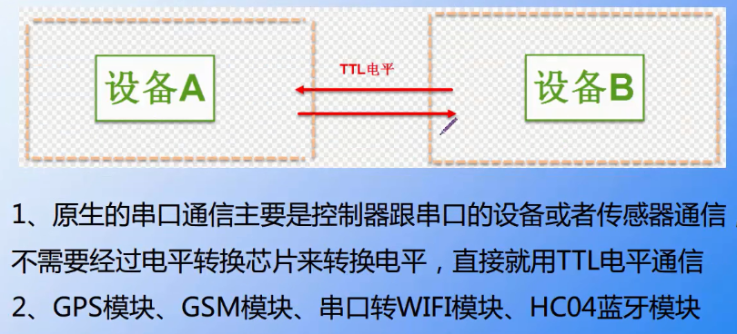
(3) Serial port to serial port (TTL - > TTL)
(4) Basic composition of serial data packet
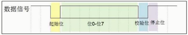
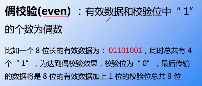
- Odd check
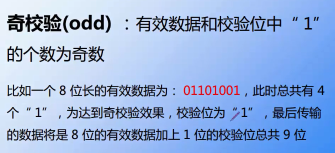
- Parity check
4, Register
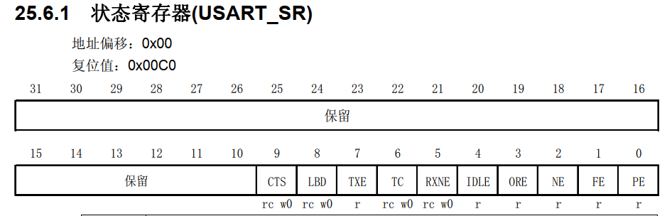
(1) Status register: USART_SR
-
TXE - transmit data register empty
When the data in the TDR register is transferred to the shift register by hardware, the TXE bit is set by hardware.
If USART_ If TXEIE in CR1 register is 1, an interrupt is generated. For USART_ Clear this bit for Dr write operation.0 - the data has not been transferred to the shift register
1 - the data has been transferred to the shift register -
TC send complete
When the transmission of a frame containing data is completed and TXE=1, the hardware will set TC position '1'.
If USART_ If tcie in CR1 = 1, an interrupt is generated. This bit is cleared by the software sequence (read USART_SR and then write USART_DR). The TC bit can also be cleared by writing '0', which is recommended only in multi cache communication.0 - sending has not been completed
1 - sending completed -
RXNE - read data register is not empty
When the data in the RDR shift register is transferred to USART_ In the Dr register, this bit (RXNE) is set by hardware.
If USART_ If rxneie in CR1 register = 1, an interrupt is generated. For USART_ The read operation of DR can clear this bit. RXNE bit can also be cleared by writing 0, which is recommended only in multi cache communication.0 - data not received
1 - the received data can be read out
(2) Data register USART_DR

(3) Control register 1 (USART_CR1)
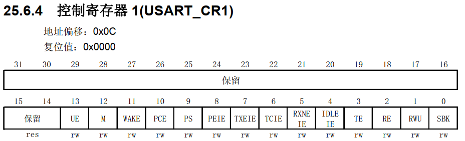
- UE is an enable serial port (1-module enable)
- TE is transmit enable (0-disable transmit, 1-enable transmit)
- RE is receive enable (0-disable receive, 1-enable receive)
- PEIE is PE interrupt enable (0-disable interrupt generation, 1-generate USART interrupt when PE of USART_SR is 1)
- TCIE is transmit completion interrupt enable (0 - interrupt generation is prohibited, 1 - USART interrupt is generated when TC in USART_SR is' 1 ')
- RXNEIE: receive buffer non air interrupt enable (0 - interrupt generation is prohibited, 1 - USART interrupt is generated when ORE or RXNE in USART_SR is' 1 ')
(4) Serial port receiving and sending data
- Send data flow
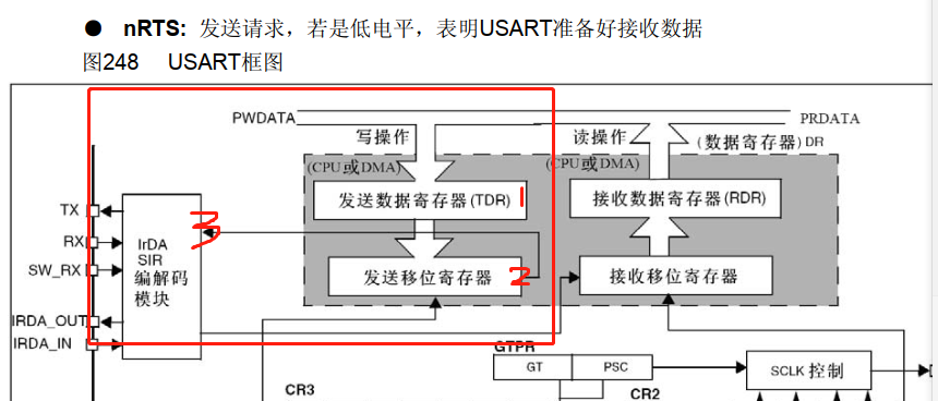
At this time, UE=1,TE=1
The sequence corresponding to the above figure is 1 - > 2 - > 3. The data comes from CPU or DMA. After the data comes, it is first put into the transmission register (TDR) and then put into the transmission data shift register. Since the data is 8 bits, it will be transmitted bit by bit (using TX pin).
- When the data is transferred from the transmit register to the transmit data shift register, TXE will be set to 1, that is, TXE=1, which means that the transmit data register is empty, but it does not mean that the data has been sent.
- Because it is necessary to send data bit by bit through the transmission shift register, if all the transmission shift register data are sent out, TC will be set to 1, that is, TC=1 indicates that the transmission of data is completed.
**
- Receiving data flow
**
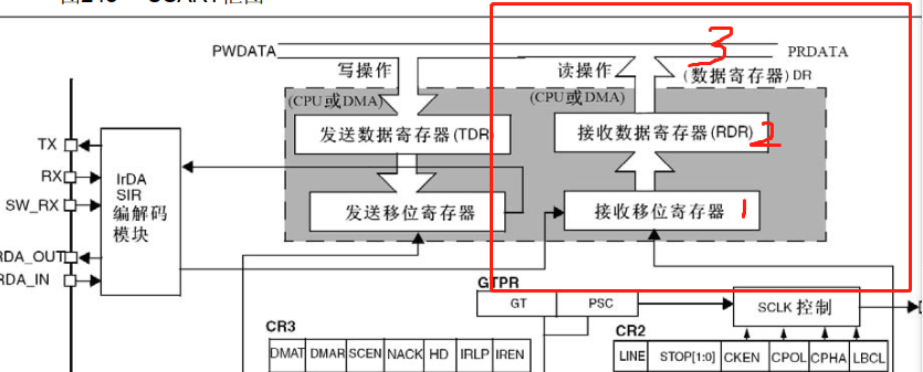
At this time, UE=1,RX=1
Data comes in from RX pin and is received bit by bit.
- First put it into the data receiving shift register
- Then transfer the data to the data receiving register (RDR). At this time, RXNE will be set to 1, that is, RXNE=1, indicating that the data receiving register is not empty (the received data can be read out)
5, STM32 firmware library functions
Several common firmware library functions
-
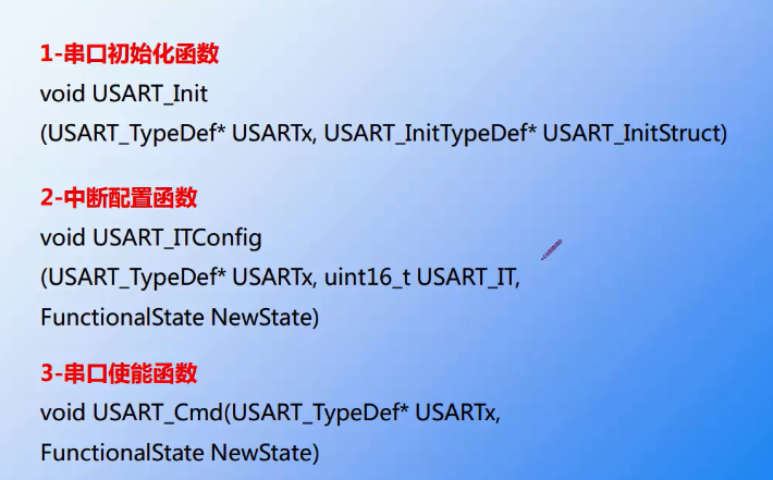
Serial port initialization function
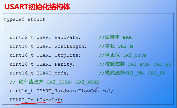
void USART_Init(USART_TypeDef* USARTx, USART_InitTypeDef* USART_InitStruct);Pin, baud rate, digit, check, clock, etc
-
Serial port enable
USART_Cmd(USART1, ENABLE); //Enable serial port - UE bit is configured
-
Interrupt enable
void USART_ITConfig(USART_TypeDef* USARTx, uint16_t USART_IT,FunctionalState NewState)
-
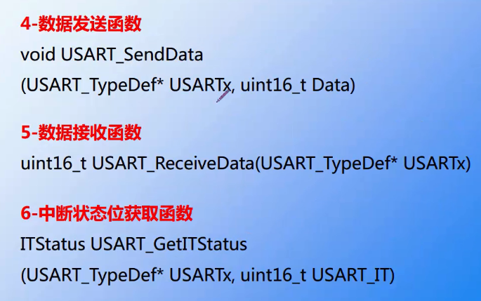
send data
STM32 library function operation USART_ The function of sending data to Dr register is to send data to serial port register USART through this function_ Dr writes a data.
void USART_SendData(USART_TypeDef* USARTx, uint16_t Data);
-
receive data
STM32 library function operation USART_ The function of Dr register to read the data received by the serial port is: the data received by the serial port can be read through this function.
uint16_t USART_ReceiveData(USART_TypeDef* USARTx);
-
Get flag bit
This function only judges the flag bit. When the corresponding interrupt function is not enabled, it is usually used to judge whether the flag bit is set to 1
Flagstatus USART_GetFlagStatus(USARTx,USART_FLAG)
-
Interrupt status bit acquisition function
It will not only judge whether the flag bit is set to 1, but also judge whether the corresponding interrupt is enabled. Therefore, in the serial port interrupt function, if you want to obtain the interrupt flag bit, you usually use this function.
ITStatus USART_GetITStatus(USART_TypeDef* USARTx, uint16_t USART_IT)
-
Clear interrupt flag bit
Void USART_Flag_Clear(USARTx,USART_FLAG)
Distinguishing description of several flag bit functions - link
6, USART application
Serial port initialization function
//Initialize IO serial port 1
//bound: baud rate
void uart_init(u32 bound){
//GPIO port settings
GPIO_InitTypeDef GPIO_InitStructure;//GPIO structure pointer
USART_InitTypeDef USART_InitStructure;//Serial port structure pointer
NVIC_InitTypeDef NVIC_InitStructure;//Interrupt packet structure pointer
//1. Enable serial port clock, serial port pin clock
RCC_APB2PeriphClockCmd(RCC_APB2Periph_USART1|RCC_APB2Periph_GPIOA, ENABLE); //Enable USART1, GPIOA clock
//2. Reset serial port
USART_DeInit(USART1); //Reset serial port 1
//3. Setting of transmit and receive pins
//USART1_ TX pa.9 (it can be seen from the figure that it is set as push-pull multiplex output)
GPIO_InitStructure.GPIO_Pin = GPIO_Pin_9; //PA.9
GPIO_InitStructure.GPIO_Speed = GPIO_Speed_50MHz;
GPIO_InitStructure.GPIO_Mode = GPIO_Mode_AF_PP; //Multiplexed push-pull output
GPIO_Init(GPIOA, &GPIO_InitStructure); //Initialize PA9
//USART1_RX PA.10 (floating input can be seen from the figure)
GPIO_InitStructure.GPIO_Pin = GPIO_Pin_10;
GPIO_InitStructure.GPIO_Mode = GPIO_Mode_IN_FLOATING;//Floating input
GPIO_Init(GPIOA, &GPIO_InitStructure); //Initialize PA10
//4. USART initialization settings
USART_InitStructure.USART_BaudRate = bound;//Generally set to 9600;
USART_InitStructure.USART_WordLength = USART_WordLength_8b;//The word length is in 8-bit data format
USART_InitStructure.USART_StopBits = USART_StopBits_1;//A stop bit
USART_InitStructure.USART_Parity = USART_Parity_No;//No parity bit
USART_InitStructure.USART_HardwareFlowControl = USART_HardwareFlowControl_None;//No hardware data flow control
USART_InitStructure.USART_Mode = USART_Mode_Rx | USART_Mode_Tx; //Transceiver mode
USART_Init(USART1, &USART_InitStructure); //Initialize serial port
#if EN_USART1_RX // If reception is enabled
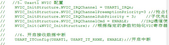
//5. Usart1 NVIC configuration
NVIC_InitStructure.NVIC_IRQChannel = USART1_IRQn;
NVIC_InitStructure.NVIC_IRQChannelPreemptionPriority=3 ;//Preemption priority 3
NVIC_InitStructure.NVIC_IRQChannelSubPriority = 3; //Sub priority 3
NVIC_InitStructure.NVIC_IRQChannelCmd = ENABLE; //IRQ channel enable
NVIC_Init(&NVIC_InitStructure); //Initializes the VIC register according to the specified parameters
//6. Enable receive data interrupt
USART_ITConfig(USART1, USART_IT_RXNE, ENABLE);//Open interrupt
#endif
//7. Enable serial port
USART_Cmd(USART1, ENABLE); //Enable serial port
}
(1) Send data
1. Function 1 - serial port sends a byte of data
void Usart_SendByte(USART_TypeDef* pUSARTx,uint8_t data)
{
	//Call firmware library function
	USART_SendData(pUSARTx,data);//Write data to serial port

	//After sending data, check whether the TXE bit is set to 1. If the sending data register is empty, it indicates that the data has been transferred to the data shift register
	//A firmware library function is also required to detect the TXE bit
	while(USART_GetFlagStatus(pUSARTx,USART_FLAG_TXE)==RESET);
	//If this bit is always 0, it will wait. Only when it is SET will it jump out of the loop (indicating that a byte has been sent)
}
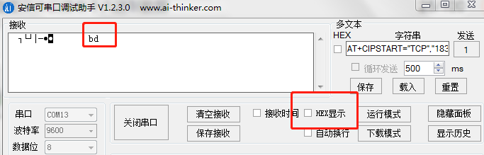
Write a statement in the main function:
//Try sending a data in the main function
Usart_SendByte(USART1,100);//Write data 100 to serial port 1
The serial debugging assistant does not display 100, but a letter d
No matter what data the serial port debugging assistant receives, it will be converted into characters
It is not a character only when sending hexadecimal data and the serial port assistant receives data in hexadecimal form
Usart_SendByte(USART1,'A');//Write A character A to serial port 1
//Character A received by serial port
Whether sending or receiving, the serial port assistant is transmitted in the form of characters
If the serial port assistant sends a number 1, if the stm32 serial port can receive it, it needs to parse according to the character '1' in the process of data parsing (regard 1 as a character, not a decimal 1)
2. Function 2 - send two bytes of data
Sometimes the sensor data may be 16 bits. How to send it? Send two bytes?
Sending two bytes of data is sixteen bits.
//Send two byte data function
void Usart_SendHalfWord(USART_TypeDef* pUSARTx,uint16_t data)
{
	//Sixteen bit data shall be sent twice, and two variables shall be defined first
	uint8_t temp_h,temp_l;//Define 8-bit variables (store the upper 8 bits and the lower 8 bits respectively)

	//First, take out the high 8 bits
	temp_h=(data&0xff00)>>8;//The lower eight bits first phase with 0 &, the lower eight bits become 0, and then shift 8 bits to the right (0xff00 is 16 bits in total)
	//Then take out the lower 8 bits
	temp_l=data&0xff;//Take out the lower 8-bit data
	//The 16 bit data is put into two variables (16 bits in total)

	//Call firmware library function
	USART_SendData(pUSARTx,temp_h);//Send the upper 8 bits first
	while(USART_GetFlagStatus(pUSARTx,USART_FLAG_TXE)==RESET);//Wait for the data to be sent

	USART_SendData(pUSARTx,temp_l);//Then send the lower 8 bits
	while(USART_GetFlagStatus(pUSARTx,USART_FLAG_TXE)==RESET);//Wait for the data to be sent

}
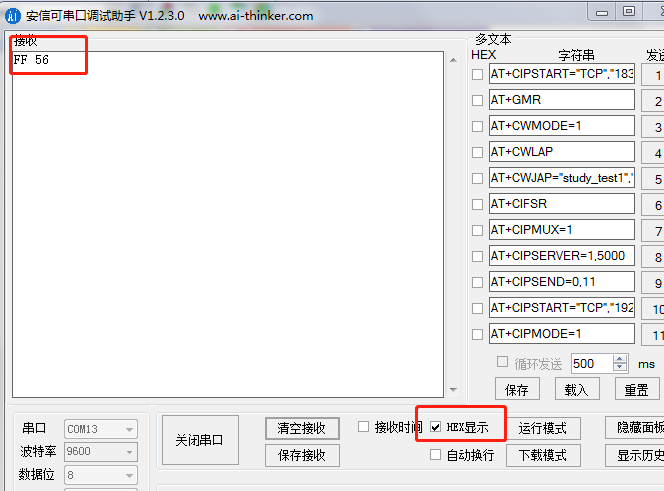
Send hexadecimal data in the main function:
Usart_SendHalfWord(USART1,0XFF56);//Send 16 bit data
The serial port assistant displays characters. If you want to receive the same data as sending, you need to select the serial port assistant as hexadecimal receiving
Serial assistant received ff 56. Although it is 16 bit data, it is displayed byte by byte. Hex ff is a byte and 56 is a byte
3. Function 3 - send an array of data
//Send an array of data
void Usart_SendArray(USART_TypeDef* pUSARTx,uint8_t *array,uint8_t num)
{
	//How much data you want to send each time is passed in through the formal parameter num. num defines 8 bits, so the function can send 255 at most
	int i;
	for(i=0;i<num;i++)
	{
		//Call the send a byte function to send data (the following two methods can be used)
		//Usart_SendByte(USART1,*array++);
		Usart_SendByte(USART1,array[i]);//Only 8 bits of data can be sent at a time
	}
	while(USART_GetFlagStatus(pUSARTx,USART_FLAG_TC)==RESET);//Wait for sending to complete
}
Judge to send a byte of data flag bit: USART_FLAG_TXE
Determine the data flag bit to send a series of bytes: USART_FLAG_TC
Define an array in the main function
uint8_t a[12]={1,2,3,4,5,6,7,8,9,10,98,100};
Send data content
Usart_SendArray(USART1,a,12);
Serial assistant: receive data in hexadecimal form
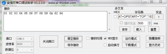
Serial assistant: receive data in non hexadecimal data form: ASCII of 1-10 cannot be displayed
4. Function 4 - send string function
//Send string
	void Usart_SendStr(USART_TypeDef* pUSARTx,uint8_t *str)//Specify the serial port and the string content to be sent
	{
		uint8_t i=0;
		//Using the do while loop, the do has already started to be sent
		do{
			//The function to send a byte needs to be called
			Usart_SendByte(USART1,*(str+i));//After sending once, the pointer address moves back one
			i++;
		}while(*(str+i)!='\0');//The last end is not equal to '\ 0'. Continue sending
		//If = '\ 0' indicates that the sending is completed
		while(USART_GetFlagStatus(pUSARTx,USART_FLAG_TC)==RESET);//Wait for sending to complete
	}
Calling a function in the main function to send a string
Usart_SendStr(USART1,"Welcome stm32\n");//At this time, characters are sent, and the serial port assistant wants to cancel hexadecimal reception
5. Function 5 - print data using the printf function
Sometimes you can't send directly with printf function
There will be an fputc at the bottom of the printf function. If you want to use it, you need to redefine it
int fputc(int ch FILE *f)
{
	//Send a byte of data to the serial port
	USART_SendData(USART1,(uint8_t)ch);
	//Wait for sending to complete
	while(USART_GetFlagStatus(USART1,USART_FLAG_TXE)==RESET);
	//Check whether the send data register is empty USART_FLAG_TXE

	return (ch);
}
Write code in the main function
printf("Serial port test experiment\n");
//You can also use putchar('a ') directly to send a character

putchar('a');//The serial assistant will receive the letter a
6. Function 6 - use getchar function
getchar() is equivalent to the scanf() function
If you use the getchar function, you also need to redefine it
Redirect the c library function scanf to the serial port. After rewriting, you can use scanf and getchar functions
redirect c Library function scanf To the serial port, which can be used after rewriting scanf and getchar function
int fgetc(FILE *f)
{
	//Wait for serial port input data
	/* With this wait, there is no need to interrupt */
	while(USART_GetFlagStatus(USART1,USART_FLAG_RXNE)==RESET);
	return (int)USART_ReceiveData(USART1);
}
If you use getchar() in the main function, you need to comment out the following interrupt setting code (as shown in the figure below), otherwise it will conflict
Because it doesn't need to be in an interrupt
Add the code of receiving data and sending data to the while(1) loop of the main function
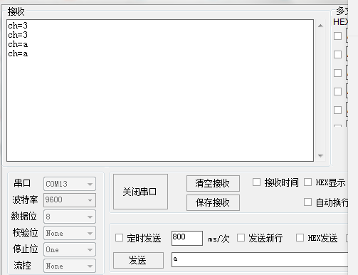
ch=getchar();
printf("ch=%c\n",ch);//Print received characters
What characters are sent by the serial port assistant, the serial port assistant will receive what characters are returned by the MCU
(2) Receive data
An interrupt occurs when data is received
USART_ITConfig(USART1, USART_IT_RXNE, ENABLE);//Open interrupt
If there is an interrupt, set the interrupt priority
NVIC_InitStructure.NVIC_IRQChannel = USART1_IRQn;
NVIC_InitStructure.NVIC_IRQChannelPreemptionPriority=3 ;//Preemption priority 3
NVIC_InitStructure.NVIC_IRQChannelSubPriority = 3;		//Sub priority 3
NVIC_InitStructure.NVIC_IRQChannelCmd = ENABLE;			//IRQ channel enable
NVIC_Init(&NVIC_InitStructure);	//Initializes the VIC register according to the specified parameters
Write interrupt service function
1. Serial port assistant sends and returns data interrupt function
What data the serial port assistant sends to the single chip microcomputer, and the single chip microcomputer automatically returns the received data to the serial port assistant
//Interrupt service function
void USART1_IRQHandler()
{
	u8 ucTemp;
	if(USART_GetFlagStatus(USART1,USART_IT_RXNE)!=RESET)
	{
		ucTemp=USART_ReceiveData(USART1);
		USART_SendData(USART1, ucTemp);
	}
}
When the external device or serial port debugging assistant sends data to the single chip microcomputer, the single chip microcomputer detects that the data receiving register is not empty, indicating that the data is coming. At this time, an interrupt is generated. Go in to the interrupt service function and call the firmware library function. Whether the flag bit is really set to 1 to avoid false interruption. If 1 is generated, call USART_ The receivedata (usart1) function receives data and puts the data in the ucTemp variable
Then call USART_SendData(USART1, ucTemp) sends the data back to the serial port assistant
2. The serial port sends data to control the led on and off
The led light is controlled by the data received through the serial port, so that there is no need to interrupt to receive. You can query the method. At this time, you should annotate the interrupt part and annotate the interrupt service function
Add the following code to the main function:
u8 ch;//Store the data received by the computer
while(1)
{
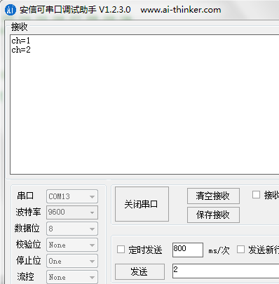
ch=getchar();//Read serial port data
printf("ch=%c\n",ch);//Print received characters
switch(ch)//Match
{
case '1':
LED0=0;break;//Open LED0
case '2':
LED1=0;break;//Open LED1
}
}
If an error occurs: refer to this link
Solution - link
Use the serial assistant to send 1 and 2 respectively to control the led light on and off
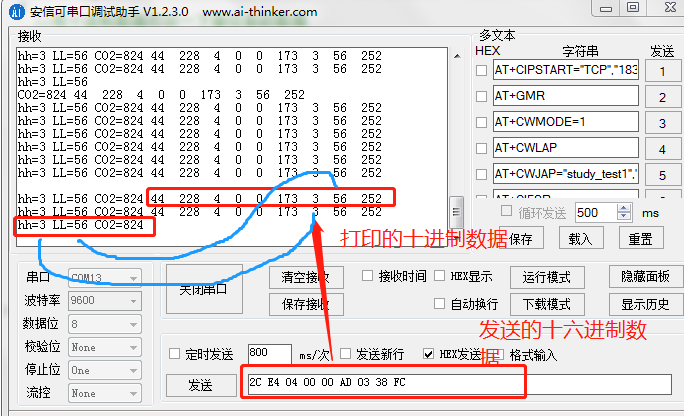
3. STM32 custom protocol receives hexadecimal data (calculate CO2 concentration using three in one gas sensor)
As mentioned earlier, if hexadecimal data receiving and sending are not checked, other cases are sent and received in the form of characters, so the hex option should be checked when sending and receiving data
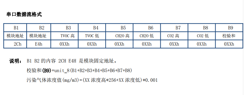
The data stream format of three in one gas sensor serial port is as follows:
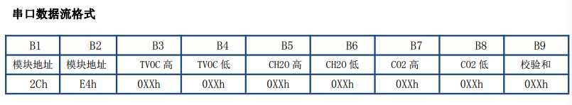
Since the first two bytes of data are fixed module addresses, they can be used as judgment criteria to define a protocol for receiving data: only when the first byte and the second byte meet the conditions, the data will be stored in the array
Module data flow: 2C E4 04 00 00 AD 03 38 FC
The data stream consists of 9 bytes, so first define an octet array that stores 9 bytes
u8 table_data[9];//This is to define an array in advance to store the received data
u8 table_cp[9];//This is to define an additional array to copy the received data into it
u16 count=0;//Received data count
Write interrupt service function
//Receive hexadecimal data using a custom protocol

void USART1_IRQHandler(void)                	//Serial port 1 interrupt service program
{
		u8 Res,i;
		if(USART_GetITStatus(USART1, USART_IT_RXNE) != RESET)  //Receive interrupt
		{
			Res =USART_ReceiveData(USART1);//(USART1->DR); 	// Read received data

			if(count==0)//If it is the first data received
			{
				table_data[count]=Res;//Save the first data to the first element in the data
				if(table_data[0]==0x2c)//Judge whether the first data received is hexadecimal 0X2C
				  count++;//If the first data is 0X2C, it means correct count + 1
			}
			else if(count==1)//When the first data is received correctly, judge the second data
			{
				if(Res==0xe4)//If the data just received is 0xE4, it indicates that the data is correct
				{
					table_data[count]=Res;//Stores the data to the second element of the array
					count++;//Received data count + 1
				}
				else//If the second character is not 0XE4, the count is cleared and received again
					count=0;
			}
			else if(count==2&&Res==0)//If the first two data are correct and the third data received is 0, the count is cleared and the data is received again
			{
				count=0;
			}
			else if(count>1&&count<9)//This is the range of data that can be received. As long as the count is within the range of data that can be received, the data can be stored
			{
				table_data[count]=Res;
				count++;
			}
			else if(count>=9)//If the received data exceeds the array size, it will be cleared and received again
			{
				count=0;
			}
   }

		memset(table_cp, 0, sizeof(table_data));//Using array table_ Empty at CP
		for(i=0;i<9;i++)//Copy the received data to table_cp array
		{
			 table_cp[i]= table_data[i];
	}
}
The above implementation is to receive and store data through a custom protocol
After receiving hexadecimal data, if you want to extract two bytes and convert them into decimal data, you first need to write a hexadecimal conversion function: (input hexadecimal data and return decimal data)
int hextoDec(int hex)
{
int sum=0,mul=1;
int i,r;
int count=0;
do{
r=hex%16;
for(i=0;i<count;i++)
mul*=16;
mul*=r;
sum+=mul;
mul=1;
count++;
}while(hex/=16);
return sum;
}
The while content of the main function is as follows:
while(1)
	{
	  if(table_cp[0]==0x2c)//If the first hexadecimal data of the array is 0X2C
		{
			//Print the received data with decimal data
			//The raw data (hexadecimal data) is 2C E4 04 00 00 AD 01 23 FC
			//The first two bits are fixed. The 7th and 8th hexadecimal data are the high and low octets of CO2 respectively
			for(i=0;i<9;i++)
			{
					printf(" %d \n",table_cp[i]);

			}

			printf("\r\n");//Add a carriage return to wrap the line
			//Convert the corresponding hexadecimal data into decimal data
			num_H=hextoDec(table_cp[6]);//High 8 bits
			num_L=hextoDec(table_cp[7]);//Lower 8 bits
			printf("hh=%d LL=%d \n",num_H,num_L);
			num=num_H*256+num_L;//The value is calculated using the CO2 concentration calculation formula
			printf("CO2=%d\n",num);

			}
	}
The verification is as follows:
As shown in the following figure: send hexadecimal data using serial port assistant:
2C E4 04 00 00 AD 03 38 FC
The 7th byte is the upper 8 bits of CO2 and the 8th byte is the lower 8 bits of CO2 concentration. Then calculate according to the calculation formula to calculate the CO2 concentration