Understand I2C bus protocol
- What is the I2C protocol? The I2C communication protocol (Inter Integrated Circuit) is composed of Phiilps
Developed by the company, because it has few pins, simple hardware implementation and strong scalability, it does not need USART and CAN
And other communication protocols are now widely used in the communication between multiple integrated circuits (ICS) in the system. - Physical layer and protocol layer of I2C protocol
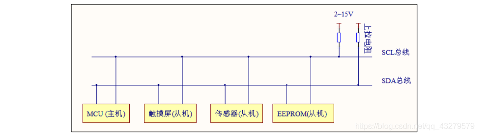
① The physical layer I2C is a bus that supports devices. Multiple I2C can be connected
Communication equipment, supporting multiple communication hosts and multiple communication slaves. For I2C bus, only two bus lines, one bidirectional serial data line (SDA), are used
, a serial clock line (SCL). Common connection modes of I2C communication equipment (refer to the figure in the wildfire data)
② Protocol layer
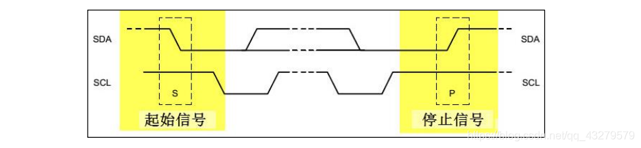
It mainly defines the start and stop signals of communication, data validity, response, arbitration, clock synchronization and address broadcasting.
Start and stop signals of communication
Data validity
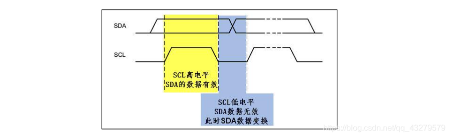
It can be seen from the figure that during I2C communication, SDA data transmission is effective only when SCL is at high level. SDA signal line is used to transmit data, and SCL signal line is used to ensure data synchronization.
response
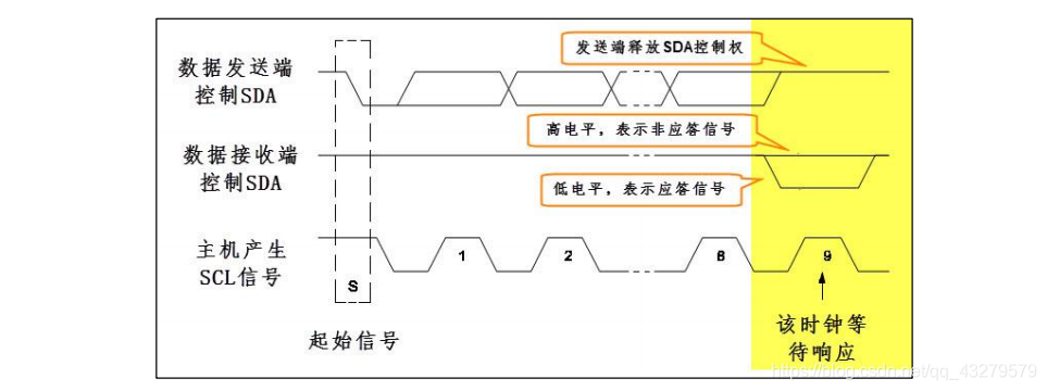
When SDA transmits data, the receiver will respond to the received data. If you want to continue transmitting data, respond to the response signal (low level), otherwise respond to the non response signal (high level).
- Two ways of I2C - hardware I2C and software I2C
① The hardware I2C directly utilizes the hardware I2C peripherals in the STM32 chip.
As long as the corresponding registers are configured for the use of hardware I2C, the peripherals will generate the timing of standard serial port protocol. After initializing I2C peripherals, you only need to set a certain register position
1. At this time, the peripheral will control the corresponding SCL and SDA lines to automatically generate I2C start signal, and there is no need for the core to directly control the level of the pin
② Software I2C
Directly use the CPU core to control the high and low level of GPIO output according to the requirements of I2C protocol, so as to simulate I2C.
Use of software I2C
When controlling the generation of I2C start signal, control the GPIO pin as SCL line to output high level, then control the GPIO pin as SDA line to complete the switching from high level to low level during this period, and finally control the SCL line to switch to low level, so as to output a standard I2C start signal.
③ The difference between the two
Hardware I2C directly uses peripherals to control pins, which can reduce the burden of CPU. However, when using hardware I2C, some fixed pins must be used as SCL and SDA, while software analog I2C can use any GPIO pin, which is relatively flexible. The usage of hardware I2C is more complex, and the flow of software I2C is clearer. If you want to understand I2C protocol in detail, you may better understand this process by using software I2C. In the process of using I2C, hardware I2C communication may be faster and more stable.
--------
Copyright notice: This article is the original article of CSDN blogger "HarrietLH" and follows the CC 4.0 BY-SA copyright agreement. Please attach the original source link and this notice for reprint.
Original link: https://blog.csdn.net/qq_43279579/article/details/111597278
Realization of AHT20 acquisition program
Example code download
- Learn about AHT20 chip. For specific information, please download the corresponding product introduction document. The data link is as follows
http://www.aosong.com/class-36.html - Specific code addition process in the sample code provided by wildfire, open an empty project that only contains the firmware library. Add relevant codes to the project. Please refer to the following link for details of adding Codes:
https://blog.csdn.net/hhhhhh277523/article/details/111397514
Analysis code
① Application process of AHT20 chip
void  read_AHT20_once(void)
{
	delay_ms(10);

	reset_AHT20();//Reset AHT20 chip
	delay_ms(10);

	init_AHT20();//Initialize AHT20 chip
	delay_ms(10);

	startMeasure_AHT20();//Start testing AHT20 chip
	delay_ms(80);

	read_AHT20();//Read the data collected by AHT20
	delay_ms(5);
}
② AHT20 chip reads data
void read_AHT20(void)
{
	uint8_t   i;

	for(i=0; i<6; i++)
	{
		readByte[i]=0;
	}
	I2C_Start();//I2C start

	I2C_WriteByte(0x71);//I2C write data
	ack_status = Receive_ACK();//Received response information
	readByte[0]= I2C_ReadByte();//I2C read data
	Send_ACK();//Send response information

	readByte[1]= I2C_ReadByte();
	Send_ACK();

	readByte[2]= I2C_ReadByte();
	Send_ACK();

	readByte[3]= I2C_ReadByte();
	Send_ACK();

	readByte[4]= I2C_ReadByte();
	Send_ACK();

	readByte[5]= I2C_ReadByte();
	SendNot_Ack();
	//Send_ACK();

	I2C_Stop();//I2C stop function
	//Judge whether the first byte read is 0x08, which is specified in the chip reading process. If there is no problem in the reading process, process the read data accordingly
	if( (readByte[0] & 0x68) == 0x08 )
	{
		H1 = readByte[1];
		H1 = (H1<<8) | readByte[2];
		H1 = (H1<<8) | readByte[3];
		H1 = H1>>4;

		H1 = (H1*1000)/1024/1024;

		T1 = readByte[3];
		T1 = T1 & 0x0000000F;
		T1 = (T1<<8) | readByte[4];
		T1 = (T1<<8) | readByte[5];

		T1 = (T1*2000)/1024/1024 - 500;

		AHT20_OutData[0] = (H1>>8) & 0x000000FF;
		AHT20_OutData[1] = H1 & 0x000000FF;

		AHT20_OutData[2] = (T1>>8) & 0x000000FF;
		AHT20_OutData[3] = T1 & 0x000000FF;
	}
	else
	{
		AHT20_OutData[0] = 0xFF;
		AHT20_OutData[1] = 0xFF;

		AHT20_OutData[2] = 0xFF;
		AHT20_OutData[3] = 0xFF;
		printf("Failed to read!!!");

	}
	printf("\r\n");
	//According to the calculation formula of temperature and humidity in AHT20 chip, the final result is obtained and displayed through serial port
	printf("temperature:%d%d.%d",T1/100,(T1/10)%10,T1%10);
	printf("humidity:%d%d.%d",H1/100,(H1/10)%10,H1%10);
	printf("\r\n");
}
Operation results
Temperature and humidity acquisition - OLED display
reference resources
Data display of 0.96 inch OLED display based on STM32
Add code
void read_AHT20(void)
{
uint8_t i;
for(i=0; i<6; i++)
{
readByte[i]=0;
}
//-------------
I2C_Start();

I2C_WriteByte(0x71);
ack_status = Receive_ACK();
readByte[0]= I2C_ReadByte();
Send_ACK();

readByte[1]= I2C_ReadByte();
Send_ACK();

readByte[2]= I2C_ReadByte();
Send_ACK();

readByte[3]= I2C_ReadByte();
Send_ACK();

readByte[4]= I2C_ReadByte();
Send_ACK();

readByte[5]= I2C_ReadByte();
SendNot_Ack();
//Send_ACK();

I2C_Stop();

//--------------
if( (readByte[0] & 0x68) == 0x08 )
{
	H1 = readByte[1];
	H1 = (H1<<8) | readByte[2];
	H1 = (H1<<8) | readByte[3];
	H1 = H1>>4;

	H1 = (H1*1000)/1024/1024;

	T1 = readByte[3];
	T1 = T1 & 0x0000000F;
	T1 = (T1<<8) | readByte[4];
	T1 = (T1<<8) | readByte[5];

	T1 = (T1*2000)/1024/1024 - 500;

	AHT20_OutData[0] = (H1>>8) & 0x000000FF;
	AHT20_OutData[1] = H1 & 0x000000FF;

	AHT20_OutData[2] = (T1>>8) & 0x000000FF;
	AHT20_OutData[3] = T1 & 0x000000FF;
}
else
{
	AHT20_OutData[0] = 0xFF;
	AHT20_OutData[1] = 0xFF;

	AHT20_OutData[2] = 0xFF;
	AHT20_OutData[3] = 0xFF;
	printf("lyy");

}
/*Display the collected temperature and humidity through the serial port
printf("\r\n");
printf("Temperature:% d%d.%d",T1/100,(T1/10)%10,T1%10);
printf("Humidity:% d%d.%d",H1/100,(H1/10)%10,H1%10);
printf("\r\n");*/
t=T1/10;
t1=T1%10;
a=(float)(t+t1*0.1);
h=H1/10;
h1=H1%10;
b=(float)(h+h1*0.1);
sprintf(strTemp,"%.1f",a);   //Call the Sprintf function to format the temperature data of DHT11 into the string array variable strTemp
sprintf(strHumi,"%.1f",b);    //Call the Sprintf function to format the humidity data of DHT11 into the string array variable strHumi
GUI_ShowCHinese(16,00,16,"Temperature and humidity display",1);
GUI_ShowCHinese(16,20,16,"temperature",1);
GUI_ShowString(53,20,strTemp,16,1);
GUI_ShowCHinese(16,38,16,"humidity",1);
GUI_ShowString(53,38,strHumi,16,1);
delay_ms(1500);
delay_ms(1500);
}
Chinese character lattice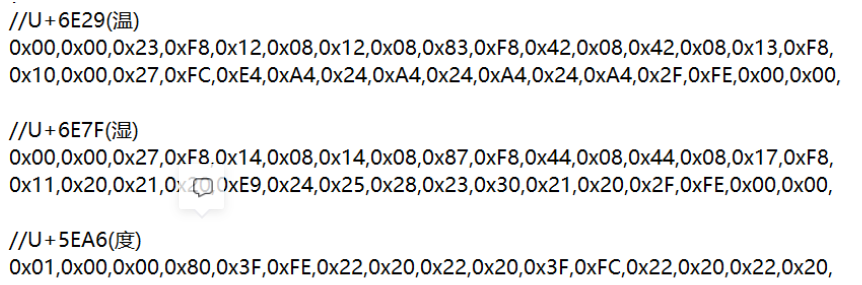
main function
#include "delay.h"
#include "usart.h"
#include "bsp_i2c.h"
#include "sys.h"

#include "oled.h"
#include "gui.h"
#include "test.h"

int main(void)
{
	delay_init();	    	       //Delay function initialization
	uart_init(115200);
	IIC_Init();

	NVIC_Configuration(); 	   //Set NVIC interrupt packet 2: 2-bit preemption priority and 2-bit response priority
	OLED_Init();			         //Initialize OLED
	OLED_Clear(0);
	while(1)
	{
		//printf("temperature and humidity display");
		read_AHT20_once();
		OLED_Clear(0);
		delay_ms(1500);
  }
}