preface
Record the process of building PingPong transceiver routine of STM32WLE5 module based on stm32subemx. The hardware platform is the blue LM401 LoraWan evaluation board of yizhilian, and the corresponding MCU model is STM32WLE5CBU6. PingPong routine has a complete data sending and receiving process, and is configured with ST's basic task scheduling, soft timing, queue and log output. It is the basic project for us to develop Lora private protocol.
1, Development environment
STM32CubeIDE is a free IDE made by ST company based on Eclipse/CDT framework and GUN GCC tool chain, and integrates STM32CubeMX. It can realize peripheral device configuration, code generation, code editing, code compilation and online debugging of STM32 series chips, and support hundreds of existing Eclipse plug-ins.
1. STM32CubeMX and STM32CubeIDE software installation
Download stm32cubemx and stm32cubeide from the official website
stm32cubemx: https://www.st.com/en/development-tools/stm32cubemx.html
stm32cubeide: https://www.st.com/en/development-tools/stm32cubeide.html
Basically, it can be determined all the way.
Although the STM32CubeIDE integrates STM32CubeMX, it is not as flexible as the separate STM32CubeMX. Separately install STM32CubeMX to facilitate the import of application routines and the generation of MDK and IAR projects.
2. Download STM32WL firmware library
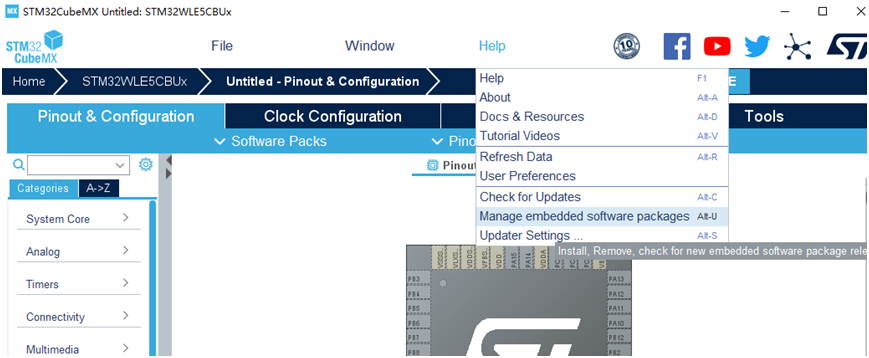
Run STM32CubeMX, HELP – > Manage embedded software packages, as shown in the figure below
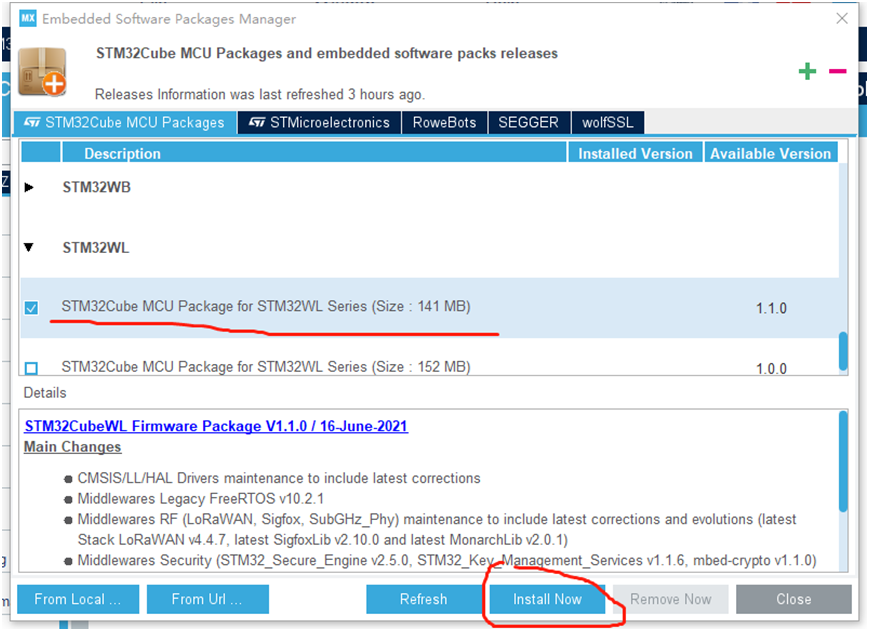
Wait for the download and installation to complete. The default installation location is C:\Users \ user \ stm32cube \ repository \ stm32cube_ FW_ WL_ V1. one
2, Hardware platform
LM401 lorawan evaluation board carries LM401 module based on STM32WLE5CB. The basic hardware circuit, on-board USB to COM and LDO are provided. USB connection computer can realize power supply, printout and input operation.
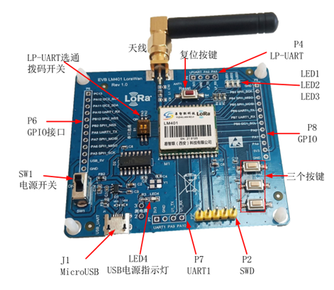
The Log output ports in PingPong routine are onboard USB to serial ports PA2 and PA3, and the software is configured as UART2 baud rate 115200-8-N-1.
3, Introduction to PingPong routine
1. PingPong routine location
\STM32Cube\Repository\STM32Cube_FW_WL_V1.1.0\Projects\NUCLEO-WL55JC\Applications\SubGHz_Phy\SubGHz_Phy_PingPong
The contents are as follows:
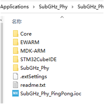
2. PingPong routine function
PingPong routine is a simple sending and receiving routine between two evaluation boards. By default, the evaluation board sends a "Ping" message as the master device and waits for a reply. The first evaluation board that receives the "Ping" message sets itself as a slave device and replies to the "Pong" message. When the master device receives the "Pong" message, it continues to send the "Ping" message. This establishes a continuous PingPong transceiver pair.
This routine can make us quickly understand the sending and receiving process of STM32WLE5 and facilitate the development of LoRa private protocol.
3. Additional functions
In the process of porting PingPong routine, when configuring STM32CubeMX, we add one ADC acquisition for subsequent acquisition reporting routine.
4, Migration of PingPong routine
1. Create STM32CubeMX project;
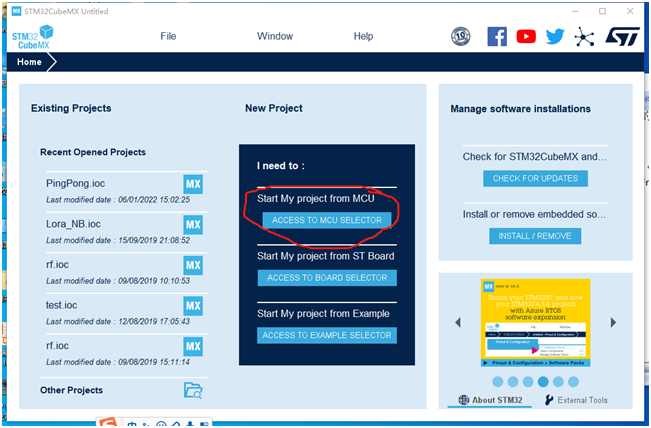
a. Open STM32CubeMX tool;
b. New project Start My Project From MCU;
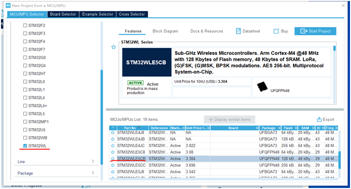
c. Select STM32WL series, select STM32WLE5CB, and double-click
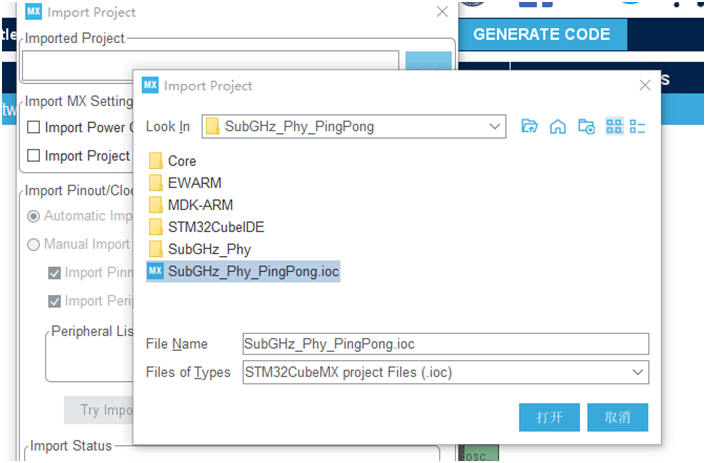
d. File menu – > import project import PingPong routine and click OK. The user name is your actual directory
C:\Users \ users \ STM32Cube\Repository\STM32Cube_FW_WL_V1.1.0\Projects\NUCLEO-WL55JC\Applications\SubGHz_Phy\SubGHz_Phy_PingPong\SubGHz_Phy_PingPong.ioc
There will be some errors in the middle because the original routine platform STM32WL55JC is BGA encapsulated, and some pins STM32WLE5CB do not.
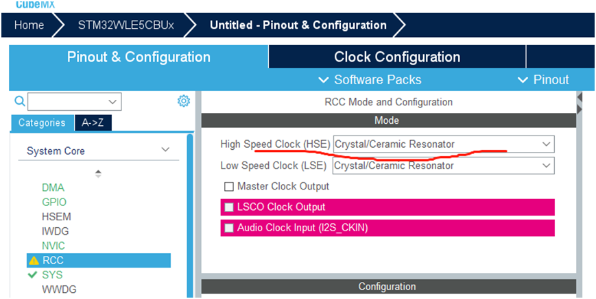
e. Configure clock input, HSE 32MHz crystal oscillator and LSE 32.768K crystal oscillator
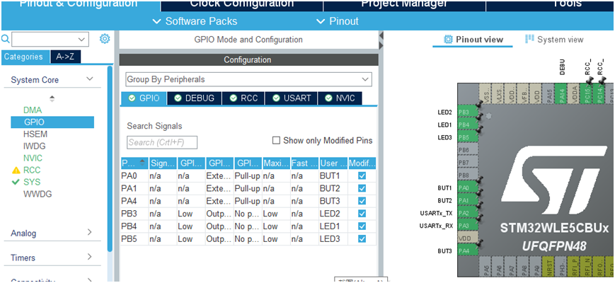
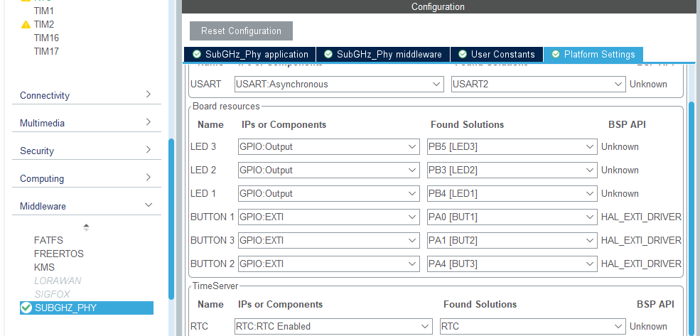
f. Configure GPIO
Three LEDs are defined as output: LED1-PB5 blue, LED2-PB4 green, LED3-PB3 red
Four function keys are defined as interrupt input and pull-up: B1-PA0, B2-PA1, B3-PA4
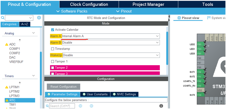
g. RTC starts Alarm A and the software is used regularly
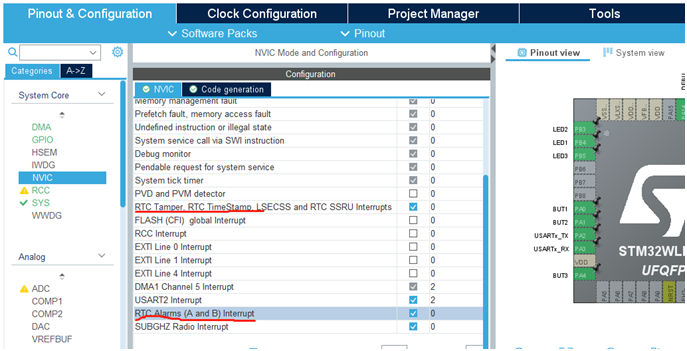
h. Start RTC interrupt
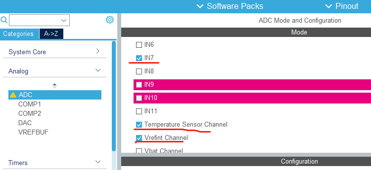
i. Configure ADC
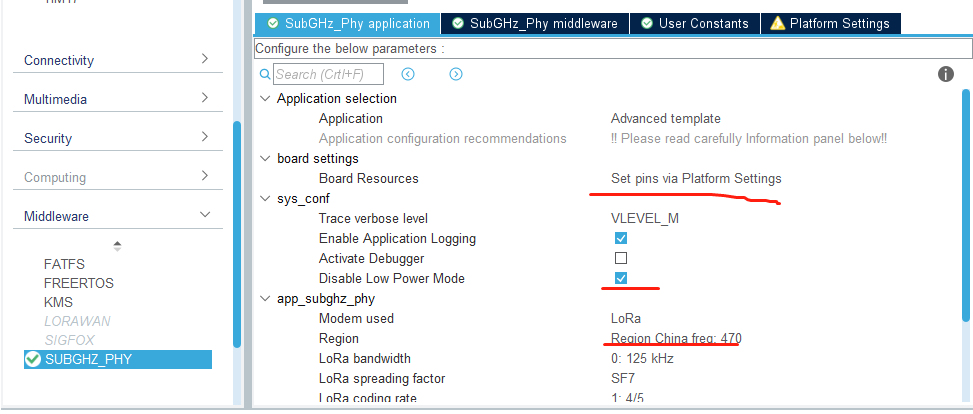
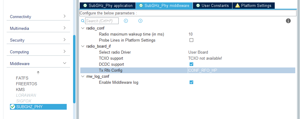
j,SUBGHZ_PHY is configured as follows
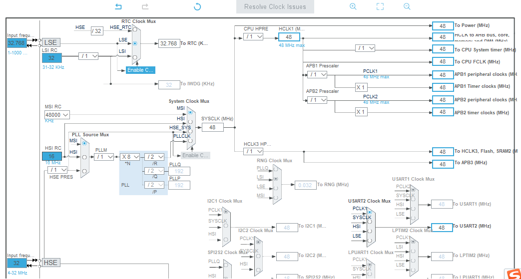
k. Clock configuration
RTC is configured with 32.768Khz, HSE 32Mhz, MCU clock 48Mhz and internal MSI RC clock
2. Production of stm32subeide project;
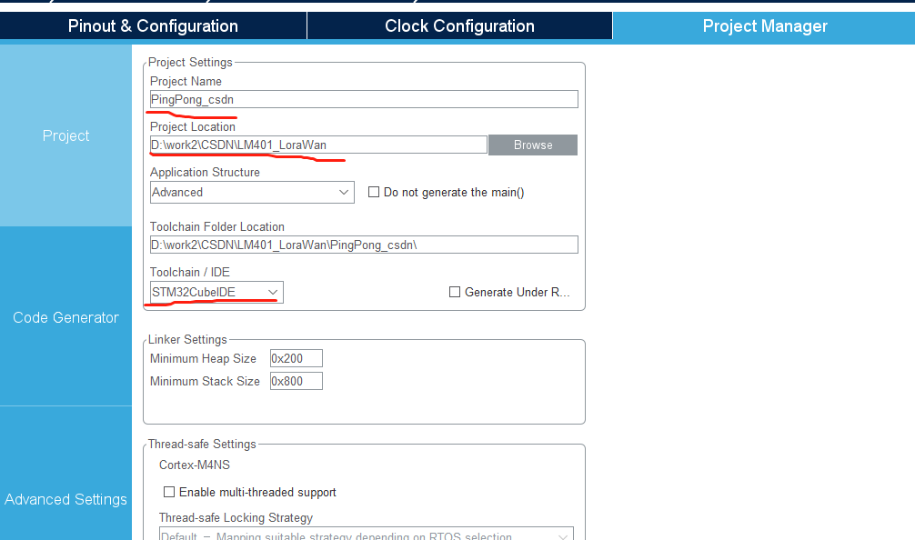
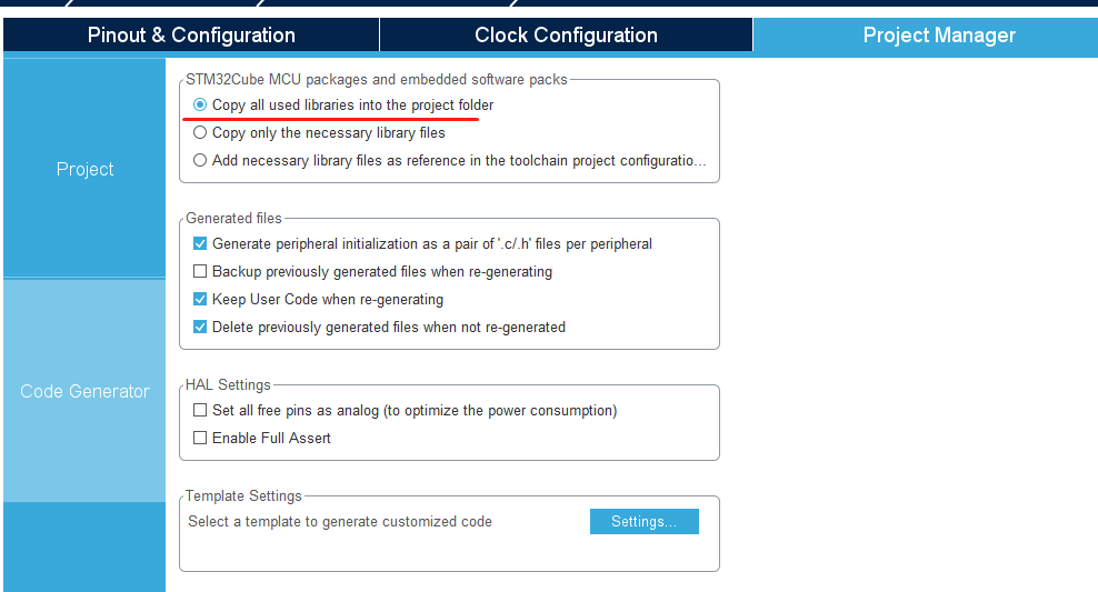
a. Project Manager configuration
b. Execute GENERATE CODE generation project
5, Engineering compilation
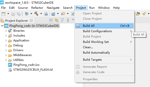
Open \ pingpong_ CSDN \ stm32cube ide directory, double-click Project opens the project. Execute Build All.
Project compiled successfully
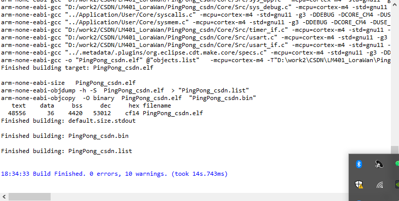
So far, the project migration is completed, but we have to carefully check the compilation details. There are 10 warnings, as shown below
                 from D:/work2/CSDN/LM401_LoraWan/PingPong_csdn/Middlewares/Third_Party/SubGHz_Phy/stm32_radio_driver/radio.c:39:
../../SubGHz_Phy/Target/radio_board_if.h:92:2: warning: #warning user to provide its board definitions pins [-Wcpp]
   92 | #warning user to provide its board definitions pins
      |  ^~~~~~~
In file included from ../../SubGHz_Phy/Target/radio_conf.h:34,
                 from D:/work2/CSDN/LM401_LoraWan/PingPong_csdn/Middlewares/Third_Party/SubGHz_Phy/stm32_radio_driver/radio_driver.c:34:
../../SubGHz_Phy/Target/radio_board_if.h:92:2: warning: #warning user to provide its board definitions pins [-Wcpp]
   92 | #warning user to provide its board definitions pins
      |  ^~~~~~~
In file included from ../../SubGHz_Phy/Target/radio_conf.h:34,
                 from D:/work2/CSDN/LM401_LoraWan/PingPong_csdn/Middlewares/Third_Party/SubGHz_Phy/stm32_radio_driver/radio_fw.c:26:
../../SubGHz_Phy/Target/radio_board_if.h:92:2: warning: #warning user to provide its board definitions pins [-Wcpp]
   92 | #warning user to provide its board definitions pins
      |  ^~~~~~~
This is because some functions that need to be migrated are not implemented.
6, Summary
So far, the migration of CubeMX project and CubeIDE project of PingPong routine is completed, and the app is opened_ subghz_ phy. C as shown below, there is only one basic framework. Subsequently, it is necessary to improve the application of undefined RF function functions and PingPong routines.
static RadioEvents_t RadioEvents;
/* USER CODE BEGIN PV */

/* USER CODE END PV */

/* Private function prototypes -----------------------------------------------*/
/*!
 * @brief Function to be executed on Radio Tx Done event
 */
static void OnTxDone(void);

/**
  * @brief Function to be executed on Radio Rx Done event
  * @param  payload ptr of buffer received
  * @param  size buffer size
  * @param  rssi
  * @param  LoraSnr_FskCfo
  */
static void OnRxDone(uint8_t *payload, uint16_t size, int16_t rssi, int8_t LoraSnr_FskCfo);

/**
  * @brief Function executed on Radio Tx Timeout event
  */
static void OnTxTimeout(void);

/**
  * @brief Function executed on Radio Rx Timeout event
  */
static void OnRxTimeout(void);

/**
  * @brief Function executed on Radio Rx Error event
  */
static void OnRxError(void);

/* USER CODE BEGIN PFP */
/* USER CODE END PFP */

/* Exported functions ---------------------------------------------------------*/
void SubghzApp_Init(void)
{
  /* USER CODE BEGIN SubghzApp_Init_1 */
  /* USER CODE END SubghzApp_Init_1 */

  /* Radio initialization */
  RadioEvents.TxDone = OnTxDone;
  RadioEvents.RxDone = OnRxDone;
  RadioEvents.TxTimeout = OnTxTimeout;
  RadioEvents.RxTimeout = OnRxTimeout;
  RadioEvents.RxError = OnRxError;

  Radio.Init(&RadioEvents);

  /* USER CODE BEGIN SubghzApp_Init_2 */
  /* USER CODE END SubghzApp_Init_2 */
}

/* USER CODE BEGIN EF */

/* USER CODE END EF */

/* Private functions ---------------------------------------------------------*/

static void OnTxDone(void)
{
  /* USER CODE BEGIN OnTxDone */
  /* USER CODE END OnTxDone */
}

static void OnRxDone(uint8_t *payload, uint16_t size, int16_t rssi, int8_t LoraSnr_FskCfo)
{
  /* USER CODE BEGIN OnRxDone */
  /* USER CODE END OnRxDone */
}

static void OnTxTimeout(void)
{
  /* USER CODE BEGIN OnTxTimeout */
  /* USER CODE END OnTxTimeout */
}

static void OnRxTimeout(void)
{
  /* USER CODE BEGIN OnRxTimeout */
  /* USER CODE END OnRxTimeout */
}

static void OnRxError(void)
{
  /* USER CODE BEGIN OnRxError */
  /* USER CODE END OnRxError */
}

/* USER CODE BEGIN PrFD */
/* USER CODE END PrFD */