preface
PingPong routine has provided a complete low-power processing framework. Users only need to open the application low-power macro definition for testing. When expanding, users only need to add low-power processing in their own functional modules to complete the low-power processing of the whole project. It is very convenient and reduces the difficulty of user development.
1, Low power mode selection
1. STM32WLE working mode
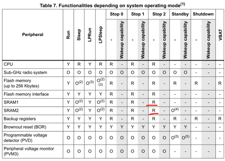
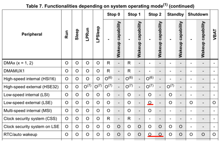
STM32WLE5 has rich working modes to choose from, such as Run, Sleep, LPRun, LPSleep, Stop0, Stop1, Stop2, Standby and Shutdown. As shown below:
2. Low power mode selection
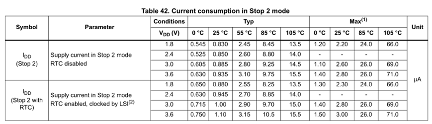
Battery powered sensors are generally in the regular reporting mode, so we need a timer; Furthermore, we hope to keep the original parameters and continue to execute the original program after waking up. Based on these two points, RTC+STOP2 mode is selected.
The typical current of RTC+STOP2 mode is 1uA, which also meets the expectations of most application scenarios.
2, Low power test execution
1. Introduction to low power processing
Low power processing centralizes the low power processing requirements of each independent module, and manages these low power tasks when the system enters idle mode. For example, when the DMA of UART2 is used to print data to the console, the system must not enter a low-power mode lower than the sleep mode because the DMA clock is turned off in the stop mode.
Each module requiring low-power management needs to be in utilities_ def. One ID is defined in H, and up to 32 IDS can be defined. As follows:
/******************************************************************************
  * LOW POWER MANAGER
  ******************************************************************************/
/**
  * Supported requester to the MCU Low Power Manager - can be increased up  to 32
  * It lists a bit mapping of all user of the Low Power Manager
  */
typedef enum
{
  /* USER CODE BEGIN CFG_LPM_Id_t_0 */

  /* USER CODE END CFG_LPM_Id_t_0 */
  CFG_LPM_APPLI_Id,
  CFG_LPM_UART_TX_Id,
  /* USER CODE BEGIN CFG_LPM_Id_t */

  /* USER CODE END CFG_LPM_Id_t */
} CFG_LPM_Id_t;
2. Low power processing
For example, the output ID of UART2 is CFG_LPM_UART_TX_Id . Every time the printout is called, util is called_ ADV_ TRACE_ Presendhook() prohibits MCU from entering STOP mode. After DMA processing is completed and it is judged that there is no data in the queue to continue output, util is called_ ADV_ TRACE_ Postsendhook() allows MCU to enter STOP mode.
When all ID S allow MCU to enter low power consumption, MCU will enter low power consumption mode. When the sequence scheduling is idle, the real execution enters the low-power action. As follows:
void UTIL_SEQ_Idle(void)
{
  /* USER CODE BEGIN UTIL_SEQ_Idle_1 */

  /* USER CODE END UTIL_SEQ_Idle_1 */
  UTIL_LPM_EnterLowPower();
  /* USER CODE BEGIN UTIL_SEQ_Idle_2 */

  /* USER CODE END UTIL_SEQ_Idle_2 */
}
UTIL_ LPM_ The implementation of enterlowpower() is located in stm32_lpm.c. Specific execution action util_ PowerDriver. The implementation of enterxmode is located in stm32_lpm_if.c.
void UTIL_LPM_EnterLowPower( void )
{
  UTIL_LPM_ENTER_CRITICAL_SECTION_ELP( );

  if( StopModeDisable != UTIL_LPM_NO_BIT_SET )
  {
    /**
     * At least one user disallows Stop Mode
     * SLEEP mode is required
     */
      UTIL_PowerDriver.EnterSleepMode( );
      UTIL_PowerDriver.ExitSleepMode( );
  }
  else
  {
    if( OffModeDisable != UTIL_LPM_NO_BIT_SET )
    {
      /**
       * At least one user disallows Off Mode
       * STOP mode is required
       */
        UTIL_PowerDriver.EnterStopMode( );
        UTIL_PowerDriver.ExitStopMode( );
    }
    else
    {
      /**
       * OFF mode is required
       */
      UTIL_PowerDriver.EnterOffMode( );
      UTIL_PowerDriver.ExitOffMode( );
    }
  }

  UTIL_LPM_EXIT_CRITICAL_SECTION_ELP( );
}
3. Turn on low power enable
The low power control ID of the system application is CFG_LPM_APPLI_Id, in SystemApp_Init(void). As follows:
/* Disable Stand-by mode */
  UTIL_LPM_SetOffMode((1 << CFG_LPM_APPLI_Id), UTIL_LPM_DISABLE);

#if defined (LOW_POWER_DISABLE) && (LOW_POWER_DISABLE == 1)
  /* Disable Stop Mode */
  UTIL_LPM_SetStopMode((1 << CFG_LPM_APPLI_Id), UTIL_LPM_DISABLE);
#elif !defined (LOW_POWER_DISABLE)
#error LOW_POWER_DISABLE not defined
#endif /* LOW_POWER_DISABLE */
Macro low_ POWER_ The disable macro is defined in sys_ In conf.h, change it to "0"
/**
  * @brief Disable Low Power mode
  * @note  0: LowPowerMode enabled. MCU enters stop2 mode, 1: LowPowerMode disabled. MCU enters sleep mode only
  */
#define LOW_POWER_DISABLE           0
3, Low power test
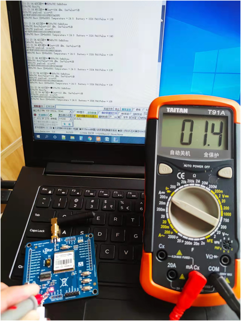
1. Disconnect the serial port strobe switch S1 and the power switch SW1;
2. When external power is supplied to the module, the multimeter is connected in series;
3. The test current is shown in the figure below. During sleep, the current is about 1.4uA.
4, Summary
STM32WLE5 microcontroller is based on STM32L4 ultra-low power technology architecture of Italian French semiconductor. It also provides SMPS dynamic voltage regulator, which can further reduce the execution power consumption of MCU. STM32WL is an ideal choice for Lora based low-power Internet of things.
Related resource links
Connection of yizhilian Demo board provided in the document: https://item.taobao.com/item.htm?spm=a1z0k.7628869.0.0.4fbb1be2qSrsJg&id=655801203935&_u=t2dmg8j26111
CubeMX project and BSP file link in PingPong:
https://download.csdn.net/download/ww2801/7627778
Low power ADC timing acquisition and reporting routine to be sorted and uploaded.