LPC2000 series - LPC2124 (timer, external interrupt) realizes running light (running light)
Jiangnan University 18 Internet of things embedded curriculum, this curriculum is a reference This blog post (also written by a senior student of Jiangda), I improved and fixed some bug s on this basis.
[note] don't copy everything completely. Everyone is mature. If you copy it 100 times, it's not yours. But if you do it seriously once, even if it's a complete reproduction, you can gain a lot! I have written very detailed and neat notes. I hope my younger brothers and sisters can study carefully when they refer to them. I have little talent and shallow learning. I hope I can help you in your study!
The following tasks are assigned for this course:
A option
Design of water lamp:
Foundation:
(1) The four pins of GPIO are used to control the four light-emitting diodes. After the first light is on for 2 seconds, the delay is 2 seconds, the second light is on, and so on. When the fourth light is on, the four diodes will be on for 2 seconds, and then cycle continuously.
(2) Keil uVision 4 software is used as the cross compilation environment.
(3) Proteus 8 Professional software is used as the simulation test of the program.
Improvement part:
(1) A pin of GPIO port is used as a key signal input to start and stop the water lamp. (press start for the first time, stop for the second time, start for the third time, and so on)
(2) A pin of GPIO port is used as a key signal input. Its function is to set the time when the light is on, which is divided into three levels: 1 second, 2 seconds and 3 seconds (press 1 for the first time, 2 seconds for the second time, 3 seconds for the third time, 1 second for the fourth time, and so on)
(3) Based on uC / OS II operating system, the above program design is completed.
The whole task is divided into four working stages (basically controlled within 10 working days) and can be implemented before and after the final examination week:
1. Install the development environment and be familiar with the basic operation of the development environment. (2 working days -- mastering the functions of the development environment)
2. Consult relevant data and prepare program code. (4 working days - flow chart of the procedure)
3. Debug relevant procedures, and modify relevant procedures during debugging. (2 working days - problems during commissioning)
4. Analyze and summarize the whole design process and submit the design report. (2 working days - general design report)
Report format: student number name class
General design report requirements:
Title (BOLD No. 4, centered Tahoma)
Class name and student number (BOLD No. 4, centered in Song typeface)
1. Design principle of water lamp. (Xiaosi Song typeface)
2. Program flow chart and code analysis. (Xiaosi Song typeface)
3. Analysis of design results and improvement. (Xiaosi Song typeface)
4. Design experience. (Xiaosi Song typeface)
Report + source program + simulation source file + shooting video (I will briefly explain and demonstrate) + job content introduction - please establish a TXT simple description in your personal folder (STM32/lpc2000 + with / without UCOS system + timer / delay + interrupt key / ordinary key)
In addition, you need to consider whether it is related to the status saving function.
development environment
Operating system: Windows10
Development software: keil uvisin5
Simulation software: Proteus 8 Professional
Development board selection: LPC2124 (using Proteus 8 Professional simulation)
Configuration environment
How old are you? Don't you still want to teach you how to match the environment??? Install all the software by yourself!
If keil4 is used, please refer to the instructions of older students for the use process This blog post.
If keil5 is used, the use process is basically the same as that of keil4. However, keil5 should install the software package by itself. After installing keil5, you can refer to it This blog post Just.
proteus doesn't need me to say more. It must be used in the course of single chip microcomputer, and the hardware course setting probability also needs to use this software. Make your own iron juice ~ O(∩ ∩) O~
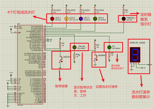
Pin connection and result display
Source code
//Jiangnan University Internet of things level 18 - MHH all rights reserved!
#include <LPC21xx.H>
#define LED1 0x00000001 					// LED1 = P0.0 port 0x1 = 0001B
#define LED2 0x00000002 					// LED1 = P0.0 port 0x1 = 0001B
#define LED3 0x00000004 					// LED3 = P0.2 port 0x4 = 0100B
#define LED4 0x00000008 					// LED4 = P0.3 port 0x8 = 1000B

#define LED5 0X000010 / / test timer 0, LED5 = P0.05 4 port 0x10 = 10000B
#define LEDT1 0x000020 / / test key 1 (pause key), ledt1 = P0.05 5 port 0x20 = 100000B

/*Lamp to be deleted*/
#define LEDT2 0x000040 / / test key 2 (gear key), ledt2 = P0.05 6 port 0x40 = 1000000B

#define BIT0 0x00000100 					// For nixie tube, P0.05 8  bit1
#define BIT1 0x00000200 					// For nixie tube, P0.05 9  bit0

#define BUT1 0x00004000                 //BUT1 = P0.14 port 0x40000 = 0100 0000 B
#define BUT2 0x00008000                 //BUT1 = P0.15 port 0x80000 = 1000 million b
typedef unsigned int uint32;

uint32 timer0Times = 0;                 //It is used to record the times of timer 0 interruption. After setting the timer 0 frequency, that is, the time.
uint32 index = 0;						//It is used to record the number of times to match the corresponding state in the "LED cycle".
uint32 timesBUT1 = 0;                   //Used to record BUT1 hits
uint32 timesBUT2 = 0;                   //Used to record the number of BUT2 clicks
uint32 delaytime = 2;                   //Set delay time

uint32 status_now[9] = {LED1, 0xF, LED2, 0xF, LED3, 0xF, LED4, 0xF, 0xF};	//Store the status of running water lamp, even number is on, and odd number is off

//Timer interrupt processing function
__irq void timer0_ISR (void)
{
	IO0CLR = LED5;
	timer0Times++;
	for (int i = 0; i < 100; i++){}		//Meng's shaking Elimination!

	if (timer0Times == delaytime)
	{
		if (index == 9){				//Reset index
			index = 0;
		}
		if (index % 2 == 0 && index < 9){				//If the light is on, the light will be on according to the status
			IO0CLR |= status_now[index];
		}
		if (index % 2 != 0 && index < 9){				//If it is off, LED1~4 are all off
			IO0SET |= status_now[index];
		}
		index++;
		IO0SET = LED5;
		timer0Times = 0;
	}
	if ( timer0Times > 3 ){
		timer0Times = 0;
	}

	T0IR = 0xFF;                        //Interrupt flag reset
	VICVectAddr = 0;                    //End of notification interrupt processing
}

__irq void EINT1_ISR(void)              //BUT1 key interrupt processing function, interrupt service program
{
    timesBUT1++;
    if (timesBUT1 == 1)
    {
        IO0CLR |= LEDT1;
        T0TCR = 0;
    }

    if (timesBUT1 == 2)
    {
        IO0SET |= LEDT1;
        T0TCR = 1;
        timesBUT1 = 0;
    }

	while((EXTINT & 0x02) != 0){        //Interrupt flag reset
		EXTINT = 0x02;                  //0x0 = 0010, corresponding to EINT1 interrupt. Write 1 to exint to clear the interrupt flag
	}
    VICVectAddr = 0;                    //End of notification interrupt processing
}

__irq void EINT2_ISR(void)              //BUT2 key interrupt processing function, interrupt service program
{
	timesBUT2++;                        //Key press record
	if(timesBUT2 == 1)                  //When first pressed
	{
		delaytime = 1;
		IO0CLR |= BIT1;
		for(int i = 0; i < 100; i++);
		IO0SET |= BIT0;					//0001
        IO0CLR |= LEDT2;
	}
	if(timesBUT2 == 2)                  //When pressed the second time
	{
		delaytime = 2;
		IO0SET |= BIT1;					//0010
		IO0CLR |= BIT0;
        IO0SET |= LEDT2;
	}
	if(timesBUT2 == 3)                  //Press BUT2 for the third time
	{
		delaytime = 3;
		IO0SET |= BIT0;					//0011
		IO0SET |= BIT1;
		timesBUT2 = 0;

        IO0CLR |= LEDT2;
	}

	while((EXTINT & 0x04) != 0){          //Interrupt flag reset
		EXTINT = 0x04;                  //0x04 = 0100, corresponding to EINT2 interrupt. Write 1 to exint to clear the interrupt flag
	}
    VICVectAddr = 0;                    //End of notification interrupt processing
}

void timer0Init (void){                 //Timer initialization function
    T0TC = 0;                           //The timer is set to 0
    T0PR = 0;                           //The timer does not divide the frequency
    T0MR0 = 11999999/2;                   //Set timer interrupt matching value
    T0MCR = (1 << 0) | (1 << 1);        //After matching, reset TC and generate interrupt. The corresponding value of the register is 0011B
    T0TCR = 0x00000001;                 //Start timer 0, T0TCR count control register, TC and PC enable count

    VICIntSelect = VICIntSelect & (~(1 << 4));	//Timer 0 is assigned as IRQ interrupt
    VICVectAddr3 = (unsigned long)timer0_ISR;  	//Bind interrupt handler address
    VICVectCntl3 = 0x20 | 4;            //Timer 0 assigned to vector IRQ channel 2, 0x20 = 10 0000
    VICIntEnable = (1 << 4);            //Timer 0 interrupt enable, corresponding to channel 4 - timer 0.
}

//EINT1 key interrupt initialization function
void EINT1_init(void){
    PINSEL0 = (PINSEL0 & 0xCFFFFFFF) | 0x20000000; //Set P0 Pin 14 is set to external interrupt, EINT1
    EXTMODE = (1 << 0) | (1 << 3);      //Set EINT1 as edge trigger
    EXTPOLAR = EXTPOLAR & 0x00000009;   //Set EINT1 and EINT2 as falling edge trigger 0x9 = 1001B

	VICIntSelect = VICIntSelect & (~(1 << 15));//EINT1 interrupt channel number is 15,
	VICIntEnable |= (1 << 15);          //Interrupt enable
	VICVectCntl1 = 0x20 | 15;           //Select channel, priority
	VICVectAddr1 = (int)EINT1_ISR;      //Interrupt handler binding
	EXTINT = 0x02;
}

//EINT2 key interrupt initialization function
void EINT2_init(void){
    PINSEL0 = (PINSEL0 & 0x3FFFFFFF) | 0x80000000; //Set P0 Pin 15 is set to external interrupt, EINT2
    EXTMODE = (1 << 0) | (1 << 3);      //Set EINT2 as edge trigger
    EXTPOLAR = EXTPOLAR & 0x00000009;   //Set EINT1 and EINT2 as falling edge trigger 0x9 = 1001B

	VICIntSelect = VICIntSelect & (~(1 << 16));//EINT2 interrupt channel number is 16,
	VICIntEnable |= (1 << 16);          //Interrupt enable
	VICVectCntl0 = 0x20 | 16;           //Select channel, priority
	VICVectAddr0 = (int)EINT2_ISR;      //Interrupt handler binding
	EXTINT = 0x04;
}

int main(void){
	PINSEL0 = 0;                        //Set all ports 0-15 as GPIO ports
	IO0DIR |= LED1;                     //Select LED1 pin as output mode
	IO0SET |= LED1;                     //The default is high level and the light is off, the same below
	IO0DIR |= LED2;
	IO0SET |= LED2;
	IO0DIR |= LED3;
	IO0SET |= LED3;
	IO0DIR |= LED4;
	IO0SET |= LED4;

    IO0DIR |= LED5;
    IO0SET |= LED5;

    IO0DIR |= LEDT1;
    IO0SET |= LEDT1;

	/*To be deleted*/
    IO0DIR |= LEDT2;
    IO0SET |= LEDT2;

	IO0DIR |= BIT0;						//Set the two control nixie tube ports to the output mode
	IO0DIR |= BIT1;

	IO0SET |= BIT0;
	IO0CLR |= BIT0;						//The initial gear is 2
	IO0SET |= BIT1;

	timer0Init();                       //timer initiated
    EINT1_init();                       //Key interrupt initialization
	EINT2_init();
    while (1)
    {
    }
}
Some knowledge points that may be used in this course that need to be queried in time:
Relatively fragmented, because it is based on my own situation. I hope it will be helpful to you!
The interrupt depends on the bottom two lines of words of CPSR flag bit P188
The channel numbers of interrupt source VIC corresponding to P190 timer 0 1 are 4 and 5 respectively
If it is set as an IRQ interrupt, it needs to be assigned an IRQ channel
Peripheral interrupt flow - P199 flow chart
The peripheral interrupt is valid → the IRQ hardware priority selector selects the IRQ channel with the highest current priority → saves the IRQ major UN service program address corresponding to the channel into the vector address register.
| register | function | remarks |
|---|---|---|
| IOxPIN, x=0, 1, 2, 3 pin register | Current level state of GPIO pin | The value of the write register is saved to → IOxSET. The level output state of the pin can be changed by modifying the value of the IOxPIN register. |
| IOxDIR direction register | The status is output → set 1, and the input is 0 | |
| IOxSET output set register | Output high level → set to 1. | |
| IOxCLR output reset register | When the pin is configured as GPIO output mode, this register can be used to control the pin output low level. | Write 1 to a bit, the pin outputs low level, and the corresponding bit of IOSET register is cleared. Invalid write 0, invalid input mode. |
| VICIntSelect interrupt select register | Allocate each of the 32 interrupt requests | Assigned as FIQ - 1, assigned as IRQ - 0 |
| Vicitenable interrupt enable register | Corresponding channel enable | 1 enabled, 0 invalid |
| Vicingenclear interrupt enable clear register | Clear multiple bits of the above enable register | 1 cleared, 0 invalid |
| VICVectAddr vector address register | When an IRQ interrupt occurs, the CPU reads this register, jumps to the corresponding address (the address of the interrupt service program), and executes the corresponding interrupt service program. | This address is copied from VICVectAddrx. |
| VICVectAddrx vector address x register | The vector address register x holds the interrupt service program address of the vector IRQ | |
| VICVectCntx vector control x register | Control the IRQ channel corresponding to x, 0 has the highest priority and 15 has the lowest priority | 32bit -- 4:0 controls 16 channels, bit5 must be set to 1 -- 0x20. P197 |
| TxIR interrupt flag register | P226 table, relevant interrupt flag should be cleared before enabling to prevent interrupt dead cycle | Reset interrupt for 1, invalid for 0. |
| TxTCR timer control register | Counter for controlling timer | 0bit - counter enable (= = 1 timer counter TC and prescaler counter PC enable count), 1bit - counter reset (= = 1 TC and PC are synchronously reset at the next rising edge of PCLK). |
| Counter of T0TC timer 0 | Before PR reaches the upper count limit, from 0x0000 0000 to 0xFFFF FFFF | |
| Prescaler register of T0PR timer 0 | Specify the maximum value of the prescaler counter. When the T0PC prescaler counter reaches this value, the timer (TC) + 1, | |
| Prescaler counter of T0PC timer 0 | + 1 per PCLK cycle, P227 | |
| T0MR0~T0MR3 matching register | Compared with the timer count value (TC), the two values are equal (T0MRx == T0TC), an interrupt occurs and the action is executed. | Execute action, controlled by T0MCR |
| T0MCR MCR matching control register | Controls the action to be performed after matching | 011 respectively control the interrupt, reset and stop of MR0MR3 |
| T0CR0~T0CR3 capture register | Associated with one or more pins to capture pin specific events | |
| T0CCR CCR capture control register | Capture the location of the event and whether an interrupt occurs | P230 |
| Ext external interrupt flag register | When the external interrupt function of the pin is selected, the corresponding interrupt signal appears and is set. Clear by writing 1. | |
| EXTMODE external interrupt mode register | Set to 0, level trigger, 1 edge trigger | 03bit control EINT03 |
| EXTPOLAR external interrupt polarity register | 0 low level falling edge trigger, 1 high level rising edge trigger | 03bit control EINT03 |
meter number implement Time clock frequency rate = F P C L K P R + 1 set Time Time between = M R × ( P R + 1 ) F P C L K transport Out frequency rate = F P C L K 2 × M P × ( P R + 1 ) Counter clock frequency {\ RM {=}} \ frac {{f {PCLK} {{PR + 1}} \ Quad timing time {\ RM {=}} \ frac {Mr {\ RM {\ times}} (PR + 1)} {{{f {PCLK}}}} \ quad output frequency {\ RM {=}} \ frac {{f {PCLK}} {2 {\ RM {\ times}} MP {\ RM {\ times}} (PR + 1)}} Counter clock frequency = PR+1FPCLK ﹐ timing time = fpclk ﹐ MR × (PR+1) output frequency = 2 × MP × (PR+1)FPCLK