Learning board: STM32F103ZET6
reference resources:
STM32F103 five minute introduction series (VII) SystemInit() function and SetSysClock() function
51 single chip microcomputer (IV) timer interrupt (+ nixie tube - 24-hour clock)
preface
This blog summarizes several related registers and library functions of SysTick timer and their usage; The SysTick timer can generate interrupts. In order to better understand SysTick and provide convenience for later interrupt summary, this blog focuses on the use of SysTick interrupts. However, SysTick interrupts are generally not used. 32 there are many timers that can generate interrupts. There is no need to use this. This blog gives examples just to better understand SysTick interrupts.
1, Systick tick timer
The reference of Systick timer is in Chapter 8 NVIC and interrupt control of Cortex-M3 authoritative guide. Then notice that this counter is a decrement counter
(1) SysTick related registers
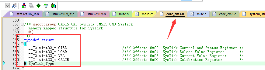
SysTick is defined in the core_cm3.h header file:
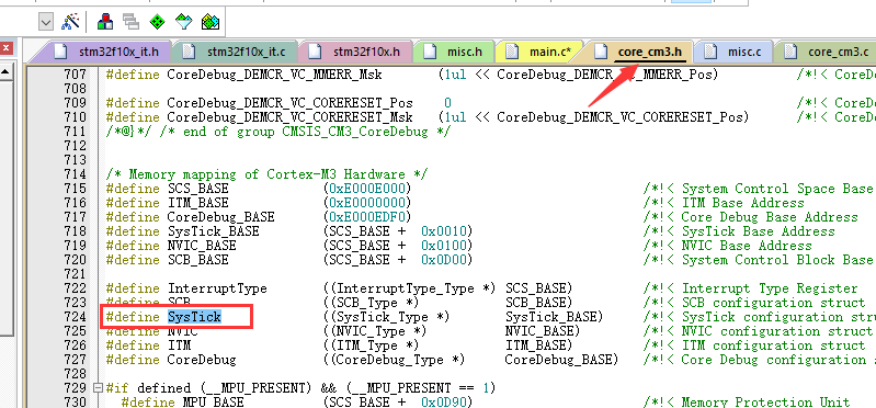
Registers related to SysTick are also defined in this file:
1. SysTick control and status register (CTRL)
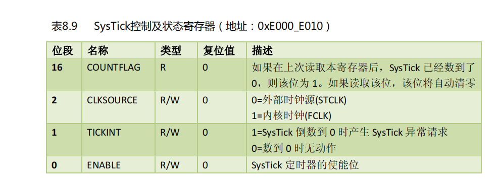
Bits 2:0 and 16 of the register are significant bits
Bit 0
For the register enable bit, set 1 to enable the register, and set 0 to disable the register. Operation mode:
SysTick->CTRL|=1;//Enable CTRL register
Bit 1
This bit sets whether to generate an interrupt. When set to 1, count down to 0 to generate an interrupt request; When set to 0, no interrupt request is generated. The interrupt has a special interrupt service function. The interrupt service function is defined in: stm32f10x_ it. In H:
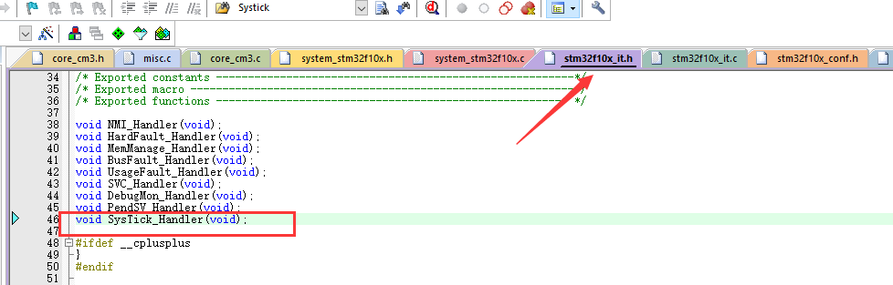
This interrupt can be used in all kinds of experiments, but it is better to use other timers. After all, there are many timers of 32. There is no need to interrupt with the timer contained in systick processor. The next blog will summarize the delay function through this systick, but also emphasize that the delay function is a pit. Don't use it unless you have to!!!
Setting method:
	SysTick->CTRL|=1<<1;//An interrupt is generated when the countdown reaches 0
	SysTick->CTRL&=0xfffd;//Counting down to 0 does not produce an interrupt
Bit 2
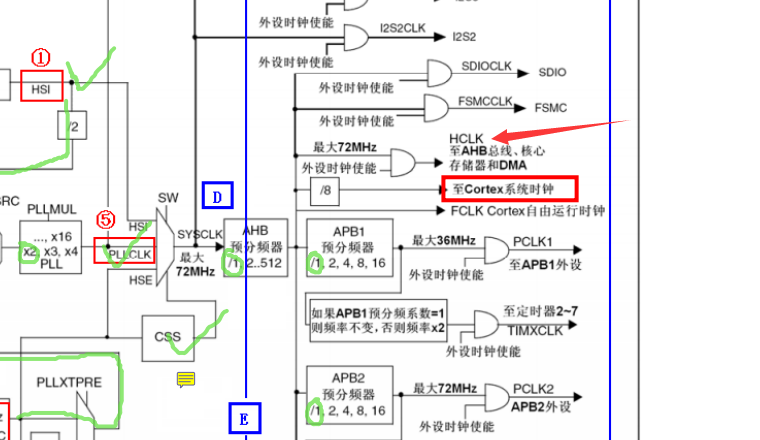
This bit selects the clock source. When the position is 0, the external clock source is used. For 32, the external clock source is 1 / 8 of the AHB bus clock. (shown by the red arrow in the figure below)
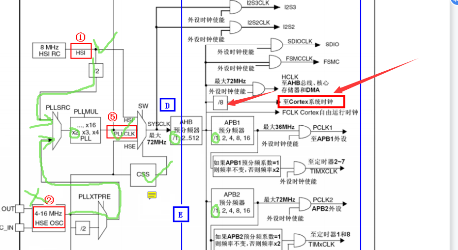
As summarized in the previous two blogs, the default state of AHB is 1 frequency division, so the clock from AHB is the system clock. In the default state, the system clock is 72MHZ. Therefore, when the software of bit 2 of the register is set to 0, the clock is 72MHZ/8=9MHZ.
When the register software is set to 1, the kernel clock is used, that is, HCLK (1 Division of sysclk clock by default) = 72MHZ. (red arrow in the figure below)
So:
Bit 2 is 0:
SysTick's clock is: (SYSCLK / (AHB frequency division coefficient)) / 8, and it is 9MHZ by default
Bit 2 is 1:
SysTick's clock is SYSCLK / (AHB frequency division coefficient), which is 72MHZ by default
Bit 16
This bit is the status flag bit. If the countdown reaches 0, this bit is set to 1. If it is not counted to 0, this bit is 0. After counting to 0, no interrupt will be generated or the initial value will be reloaded to enter the next countdown. The following code can be used to determine whether the count reaches 0:
if((SysTick->CTRL&0x10000)!=0)//Count down to 0
		{

		}

		else//Not countdown to 0
		{

		}
2. SysTick reload value register (LOAD)
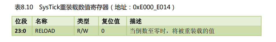
The register is also a 32-bit register, but the significant bit is 24 bits and the upper 8 bits are reserved bits. Then the maximum loaded value of the register is (2 ^ 24) - 1 = 16777215, so the overloaded value is defined as u32 and uint32_t type.
Reload operation:
SysTick->LOAD=(u32)a number;
3. SysTick current value register (VAL)
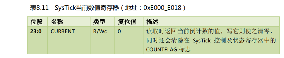
This register is used to obtain the value of the current countdown (read operation). If you write to it, it will be cleared, and bit 24 of the CTRL register will be cleared. (this write operation is generally not used)
Operations on this register:
u32 temp=SysTick->VAL;
4. SysTick calibration value register (CALIB)
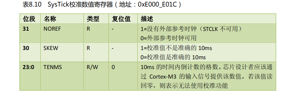
This register is generally not used. Just understand it.
Through this register, the system can run on different CM3 products and generate a constant SysTick interrupt frequency. The value of TENMS can be directly written into the reload register. In this way, SysTick exceptions can occur every 10ms as long as the system limit is not exceeded.
2, SysTick related library functions
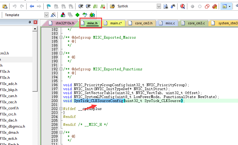
1. Clock source selection function SysTick_CLKSourceConfig()
This function is defined in misc H header file:
Open function body:
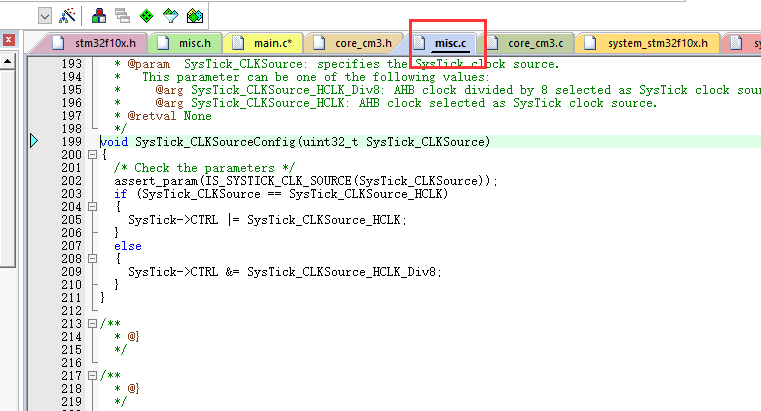
The code is very simple. Let's take a look at the parameters passed by this function:
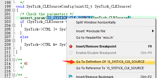
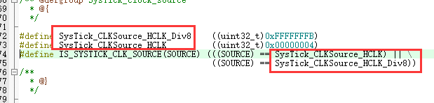
As the name suggests, it is what we said when summarizing the CTRL register before. The clock source can be HCLK and HCLK/8.
Take a closer look at the code:
  if (SysTick_CLKSource == SysTick_CLKSource_HCLK)
  {
    SysTick->CTRL |= SysTick_CLKSource_HCLK;
  }
  else
  {
    SysTick->CTRL &= SysTick_CLKSource_HCLK_Div8;
  }
When the passed parameter is SysTick_CLKSource_HCLK,SysTick_CLKSource_HCLK_Div8, execute the corresponding line of code respectively.
Replace the ID with a hexadecimal number:
  if (SysTick_CLKSource == SysTick_CLKSource_HCLK)
  {
    SysTick->CTRL |= 0x00000004;
  }
  else
  {
    SysTick->CTRL &= 0xFFFFFFFB;
After systick - > Ctrl | = 0x00000004 is executed, the second bit of the CTRL register is 1, that is, we summarized earlier: the clock source of HCLK kernel is used, and the default state is 72MHZ (= SYSCLK) (AHB defaults to 1 Frequency Division)
After systick - > CTRL & = 0xfffffb is executed, the second bit of CTRL register is 0, that is, we summarized earlier: use an external clock source, i.e. HCLK/8. In the default state, 9MHZ (= SYSCLK/8) (AHB defaults to 1 Frequency Division)
2. SysTick configuration function SysTick_Config()
(1) Function implementation
This function is defined in the core_cm3.h, after all, is a simple timer that comes with Cortex-M3. It is reasonable to define it in this folder.
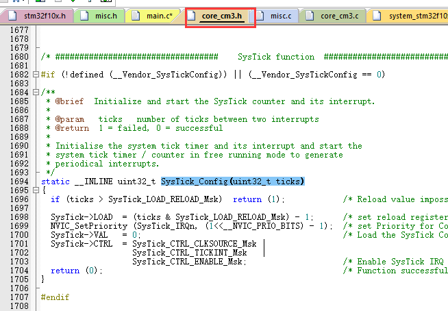
static __INLINE uint32_t SysTick_Config(uint32_t ticks)
{
  if (ticks > SysTick_LOAD_RELOAD_Msk)  return (1);            /* Reload value impossible */

  SysTick->LOAD  = (ticks & SysTick_LOAD_RELOAD_Msk) - 1;      /* set reload register */
  NVIC_SetPriority (SysTick_IRQn, (1<<__NVIC_PRIO_BITS) - 1);  /* set Priority for Cortex-M0 System Interrupts */
  SysTick->VAL   = 0;                                          /* Load the SysTick Counter Value */
  SysTick->CTRL  = SysTick_CTRL_CLKSOURCE_Msk |
                   SysTick_CTRL_TICKINT_Msk   |
                   SysTick_CTRL_ENABLE_Msk;                    /* Enable SysTick IRQ and SysTick Timer */
  return (0);                                                  /* Function successful */
}
This function is composed of return values. It returns 0 and 1. Returning 0 means that the setting is successful, and returning 1 means that the reload fails (note that it is not a setting failure)
I'm looking at SysTick_LOAD_RELOAD_Msk identification:
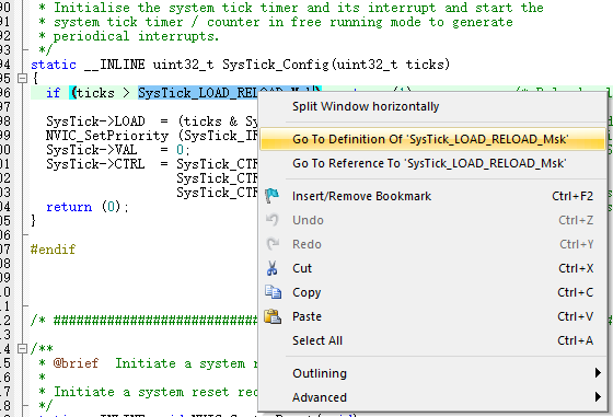

This value is the maximum reload value we summarized earlier, that is, the LOAD register 23:0 is all 1 If so, if (ticks > systick_LOAD_reload_msk) return (1); This line of code is not difficult to understand. Because the reload value passed exceeds the maximum loadable value, a return of 1 indicates that the reload failed.
Although an error message of 1 can be returned, the program does not end and will continue to execute: systick - > Load = (ticks & systick_load_reload_msk) - 1; This line of code is to set the loading value. If the ticks is less than or equal to the maximum loadable value, the result will still be ticks after the passed loading value ticks and 0xffffff bit sum operation; If the ticks is greater than the maximum loadable value, (eg: 0x1000000, the result is 0; eg0x1000001, the result is 1) after bit and operation, the reload value will be calculated to a number less than the maximum loadable value.
Then set the interrupt priority. Don't summarize this first. After summarizing the interrupt, it should be clear.
SysTick->VAL = 0; This line of code is a write operation to val. as summarized earlier, if it is a write operation, clear the Val register (note that this is a method to clear the Val register without interruption!) At the same time, clear the bit 24 of CTRL to 0. At this time, although Val is 0, the bit 24 of CTRL is still 0. The system judges that the counter does not count down to 0, so there will be no interrupt.
Next code:
  SysTick->CTRL  = SysTick_CTRL_CLKSOURCE_Msk |
                   SysTick_CTRL_TICKINT_Msk   |
                   SysTick_CTRL_ENABLE_Msk;
Change the identification to hexadecimal number: (ul indicates unsigned long integer)
SysTick->CTRL = 1ul | 1ul |1ul;
Namely:
SysTick->CTRL = 1;
That is, assign 1 to bit 0 of CTRL register and 0 to other bits.
(2) Summary
After setting through this function, the status is as follows:
① If the reload value is greater than the maximum loadable value, return 1, continue to execute downward, and finally return 0
② If the reload value is less than or equal to the maximum loadable value, continue down and finally return 0
③ If the reload value is greater than the maximum loadable value, the reload value will be reduced to a number less than the maximum loadable value through bit sum operation.
④ Clear VAL register
⑤ Enable SysTick timer
3. Interrupt service function SysTick_Handler()
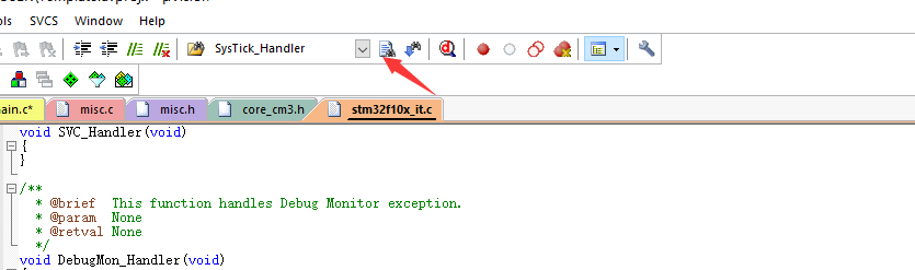
The interrupt service function is defined in stm32f10x_it.h medium
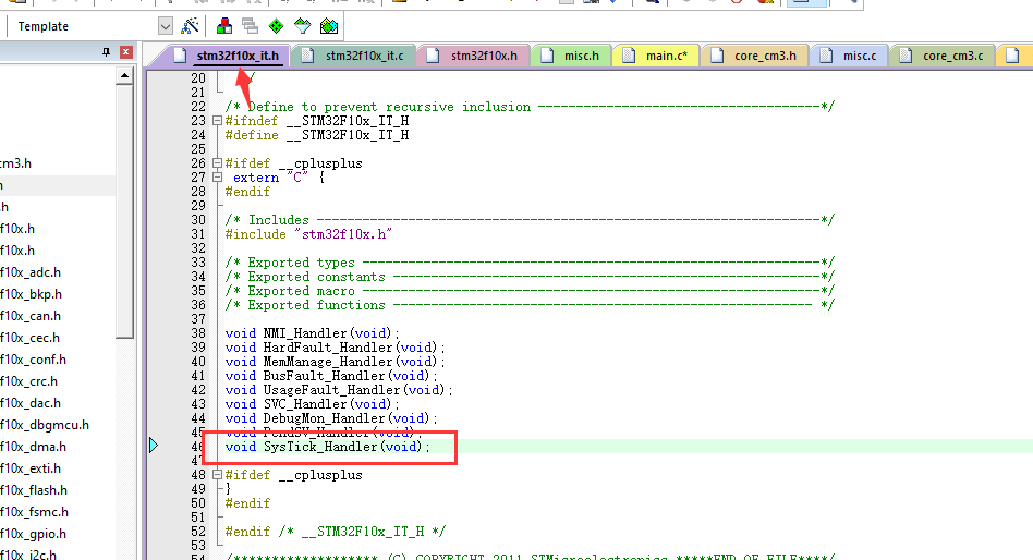
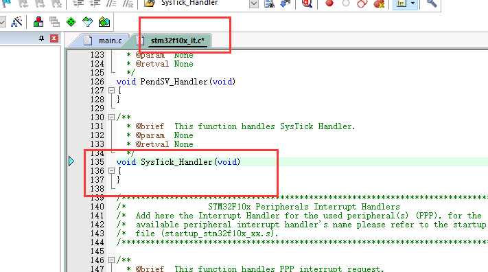
This function has a function body by default. Sometimes if you don't want to use this function body, you can comment it out, and then copy the interrupt service function framework to your desired file to continue writing. Of course, if the SysTick counter does not generate an interrupt (CTRL register bit 1 is always set to 0), you don't need to write the interrupt service function.
3, Write an LED flashing experiment with SysTick (0.5s cycle)
The LED configuration is no longer summarized. You can see my first blog in this series.
1. Initialize LED
#include "stm32f10x.h"
#include "led.h"
 int main(void)
 {
	 LED_Init();
 }
2. Set SysTick clock source
In order to slow down the count of SysTick counter, the reload value shall be as small as possible, and a small clock cycle shall be adopted, that is, 1 / 8 of the external clock source and AHB bus clock.
	 SysTick_CLKSourceConfig(SysTick_CLKSource_HCLK_Div8); //Select external clock source 72MHZ/8=9MHZ
	 //SysTick->CTRL &=0xFFFFFFFB
3. Set CTRL register
After counting to 0, an interrupt will be generated and enter the interrupt service function, so bit 1 of CTRL register is set to 1:
SysTick->CTRL|=1<<1;//Allow interrupts
4. Set reload value
SysTick clock is 9MHZ, and one clock cycle is counted, then:
1s count: 9000000 times
1ms count: 9000 times
1us count: 9 times
If LED0 is allowed to flash every 0.5s, that is, it is interrupted every 0.5s, the LED0 is reversed in the interrupt service function.
You need to count 0.5 × 9000000 = 4500000 times
The maximum reloadable value is 0xffffff=16777215, which does not exceed the maximum reloadable value, so LOAD 4500000 into the LOAD register and count once.
SysTick->LOAD=4500000;//Reload initial value
5. Clear VAL register
#include "stm32f10x.h"
#include "led.h"
 int main(void)
 {
	 LED_Init();
	 SysTick_CLKSourceConfig(SysTick_CLKSource_HCLK_Div8); //Select external clock source 72MHZ/8=9MHZ
	 //SysTick->CTRL &=0xFFFFFFFB
	 SysTick->CTRL|=1<<1;//Allow interrupts
	 SysTick->LOAD=4500000;//Reload initial value
	 SysTick->VAL=0;//Clear VAL register
 }
6. Enable the SysTick clock and start counting
SysTick->CTRL|=1;//Enable the SysTick clock and start counting
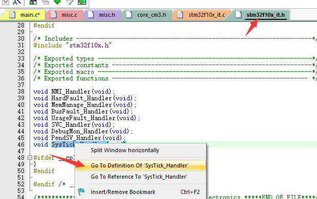
7. Mask the original interrupt service function
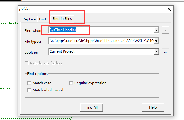
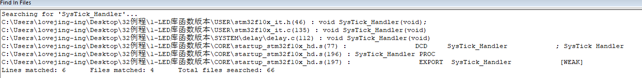
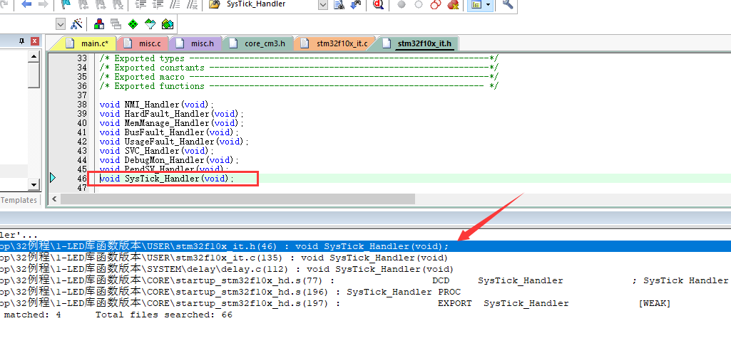
The interrupt service function is defined in stm32f10x_it.h, you can use global search:
Or Ctrl+F directly
Open function body:
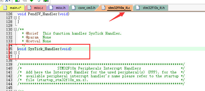
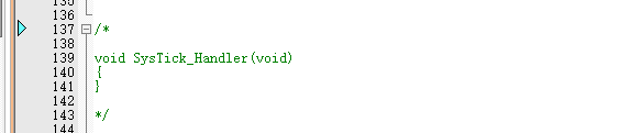
Comment it out
8. Write interrupt service function
void  SysTick_Handler()
{
	LED0=~LED0;
}
This code can only last once, because the initial value is not reloaded after the count is completed, and the next step is required
9. Initial value of repeated loading
Load the initial value again in the interrupt service function. Load the initial value every interrupt:
oid  SysTick_Handler(void)
{
	LED0=~LED0;
	SysTick->LOAD=4500000;//Reload initial value
	SysTick->VAL=0;//Clear VAL register
}
10. Complete code
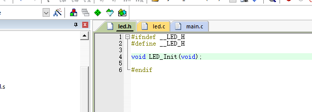
//led.h
#ifndef __LED_H
#define __LED_H
void LED_Init(void);
#endif
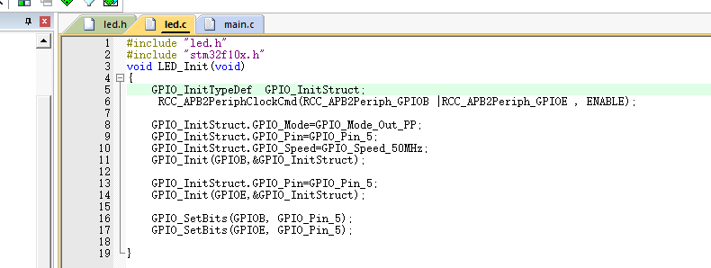
//led.c
#include "led.h"
#include "stm32f10x.h"
void LED_Init(void)
{
	GPIO_InitTypeDef  GPIO_InitStruct;
	 RCC_APB2PeriphClockCmd(RCC_APB2Periph_GPIOB |RCC_APB2Periph_GPIOE , ENABLE);

	GPIO_InitStruct.GPIO_Mode=GPIO_Mode_Out_PP;
	GPIO_InitStruct.GPIO_Pin=GPIO_Pin_5;
	GPIO_InitStruct.GPIO_Speed=GPIO_Speed_50MHz;
	GPIO_Init(GPIOB,&GPIO_InitStruct);

	GPIO_InitStruct.GPIO_Pin=GPIO_Pin_5;
	GPIO_Init(GPIOE,&GPIO_InitStruct);

	GPIO_SetBits(GPIOB, GPIO_Pin_5);
	GPIO_SetBits(GPIOE, GPIO_Pin_5);
}
//main.c
#include "stm32f10x.h"
#include "led.h"
#include "sys.h"
#define LED0 PBout(5)	// DS0
 int main(void)
 {
	 LED_Init();
	 SysTick_CLKSourceConfig(SysTick_CLKSource_HCLK_Div8); //Select external clock source 72MHZ/8=9MHZ
	 //SysTick->CTRL &=0xFFFFFFFB
	 SysTick->CTRL|=1<<1;//Allow interrupts

	 SysTick->LOAD=4500000;//Reload initial value
	 SysTick->VAL=0;//Clear VAL register
	 SysTick->CTRL|=1;//Enable the SysTick clock and start counting
	 while(1)
	 {
	 }
 }

void  SysTick_Handler(void)
{
	LED0=~LED0;
	SysTick->LOAD=4500000;//Reload initial value
	SysTick->VAL=0;//Clear VAL register
}
11. Effect moving picture
4, Write an LED flashing experiment with SysTick (3s cycle)
The previous count did not exceed the maximum loadable value. This time, conduct an experiment that exceeded the maximum loadable value, and let LED3s flash
1. Train of thought
SysTick clock is 9MHZ, and one clock cycle is counted, then:
1s count: 9000000 times
1ms count: 9000 times
1us count: 9 times
If the LED is on and off every 3s, the required count value will be interrupted once:
9000000×3=27000000>(2^24 -1)
So it needs to be reloaded many times
If you reload 10 times, the value of each load is 2700000
Changes in the procedure:
2. Complete code
//led.h
#ifndef __LED_H
#define __LED_H
void LED_Init(void);
#endif
//led.c
#include "led.h"
#include "stm32f10x.h"
void LED_Init(void)
{
	GPIO_InitTypeDef  GPIO_InitStruct;
	 RCC_APB2PeriphClockCmd(RCC_APB2Periph_GPIOB |RCC_APB2Periph_GPIOE , ENABLE);

	GPIO_InitStruct.GPIO_Mode=GPIO_Mode_Out_PP;
	GPIO_InitStruct.GPIO_Pin=GPIO_Pin_5;
	GPIO_InitStruct.GPIO_Speed=GPIO_Speed_50MHz;
	GPIO_Init(GPIOB,&GPIO_InitStruct);

	GPIO_InitStruct.GPIO_Pin=GPIO_Pin_5;
	GPIO_Init(GPIOE,&GPIO_InitStruct);

	GPIO_SetBits(GPIOB, GPIO_Pin_5);
	GPIO_SetBits(GPIOE, GPIO_Pin_5);
}
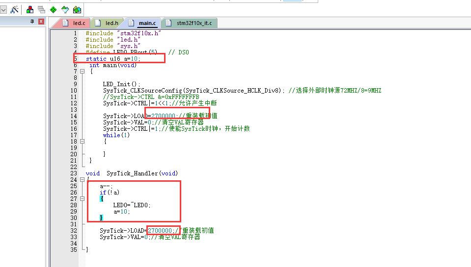
//main.c
#include "stm32f10x.h"
#include "led.h"
#include "sys.h"
#define LED0 PBout(5)	// DS0
static u16 a=10;
 int main(void)
 {
	 LED_Init();
	 SysTick_CLKSourceConfig(SysTick_CLKSource_HCLK_Div8); //Select external clock source 72MHZ/8=9MHZ
	 //SysTick->CTRL &=0xFFFFFFFB
	 SysTick->CTRL|=1<<1;//Allow interrupts

	 SysTick->LOAD=2700000;//Reload initial value
	 SysTick->VAL=0;//Clear VAL register
	 SysTick->CTRL|=1;//Enable the SysTick clock and start counting
	 while(1)
	 {

	 }
 }

void  SysTick_Handler(void)
{
	a--;
	if(!a)
	{
		LED0=~LED0;
		a=10;
	}
	SysTick->LOAD=2700000;//Reload initial value
	SysTick->VAL=0;//Clear VAL register
}
3. Effect moving picture