1, Purpose and task of the experiment
1. Familiar with the characteristics and working principle of single bus and DS18B20 sensor.
2. Master the hardware structure and program design method of digital thermometer.
2, Introduction to experimental principle
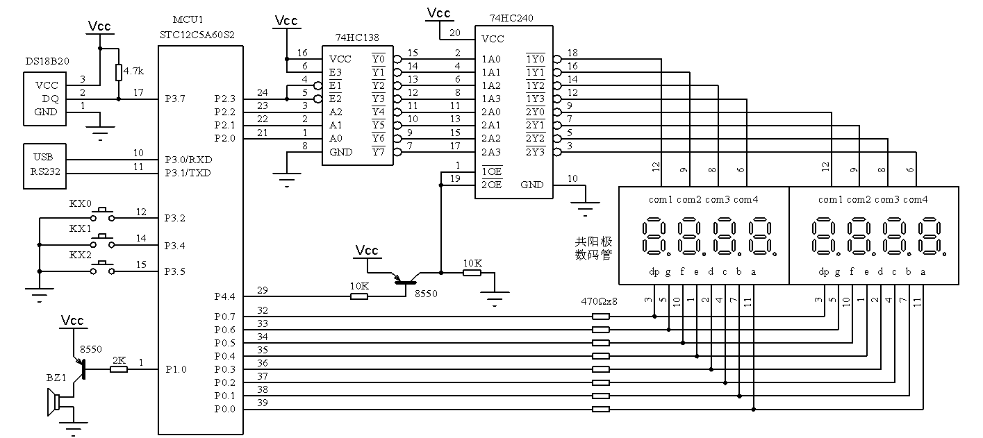
ZSC-1 experimental box is equipped with DS18B20 digital temperature sensor, LED nixie tube, buzzer, key and other peripherals. In addition, it is also equipped with RS232 and USB external communication interfaces, which provides good hardware support for realizing the function of digital thermometer. Figure 3.12.1 shows the specific hardware circuit. DS18B20 data line DQ and MCU P3 The 7-port line is connected, and the single chip microcomputer simulates the single bus timing through the program to realize the communication with DS18B20. LED nixie tube is used to display the temperature measured by DS18B20 (actually only 3 digits), buzzer BZ1 is used for overtemperature alarm, and keys KX0~KX2 are used for alarm temperature setting. The communication interface is used to connect PC and realize functions such as temperature upload.
In order to complete a temperature acquisition, the single-chip microcomputer first initializes the DS18B20 according to the timing requirements of the single bus protocol. After successful initialization, it sends the command word CCH and skips the ROM sequence code matching operation (when multiple DS18B20 are connected in parallel, it is necessary to select a DS18B20 through the ROM sequence code matching command), then sends the command word 44H and starts the DS18B20 for temperature conversion. The time required for one conversion is 93.75~750ms (depending on the bit setting of DS18B20, the conversion time corresponding to 12 bits is 750ms). After that, the MCU reinitializes DS18B20, sends CCH and BEH commands successively, and then reads two consecutive bytes to obtain the 16 bit temperature value (the low byte comes first).
DS18B20 temperature value adopts 16 bit complement. D-1~D-4 in the low byte are decimal places. All are valid at 12 bit resolution, D-4 is invalid at 11 bit resolution, D-4 and D-3 are invalid at 10 bit resolution, and D-4, D-3 and D-2 are invalid at 9 bit resolution. S in the high byte is the sign bit. When the temperature is positive, it is all 0, and when the temperature is negative, it is all 1.
All bus read and write operations of DS18B20 begin with an initialization sequence. The single bus is usually in the high-level state. During initialization, the single-chip microcomputer pulls the single bus down at least 480us and then releases it (the bus will be quickly pulled up through the 4.7K pull-up resistance), so as to send out a reset pulse. Under normal circumstances, DS18B20 will wait for 15-60us after detecting the release of the bus, and then pull down the bus by 60-240us before releasing. At this point, an initialization sequence is completed.
3, Experiment contents and steps
1. Design the program, use DS18B20 to detect the temperature and display it through nixie tube. (brief introduction)
2. Improve program 1 and set the buzzer to alarm when the temperature exceeds 31.5 ℃. The procedure is as follows:
//*****************************Header file declaration****************************
#include <reg51.h>
//****************************Data type definition***************************
typedef unsigned char uint8;
typedef unsigned int  uint16;
//****************************I/O port line statement****************************
#define SEG_CODE_PORT P0
#define BIT_CODE_PORT P2
sbit    DS18B20_DATA=P3^7;
sbit    BUZZ=P1^0;
//************************Constant array (segment code table) declaration*********************
uint8 code SegCodeTable[]=
    {0xc0,0xf9,0xa4,0xb0,0x99,0x92,0x82,0xf8,0x80,0x90};
//****************************Global variable declaration***************************
int Temperature;
//****************************Function prototype declaration***************************
void   DS18B20Init();
void   DS18B20BitWrite(bit Bit);
bit    DS18B20BitRead();
void   DS18B20ByteWrite(uint8 Byte);
uint8  DS18B20ByteRead();
void   GetTemperature();
void   DispTemperature();
void   Delay(uint16 ms);
void   AlarmCheck();
//*******************************Main function******************************
void main()
{
    while(1)
      {
          GetTemperature();        //Collect current temperature
          DispTemperature();        //Displays the current temperature
		   AlarmCheck();
	   }
}
//*************************DS18B20 initialization function*************************
void DS18B20Init()
{
    uint16  i;
    while(1)
      {
        DS18B20_DATA=0;
        i=640;
        while(--i);       //Delay 800us(STC12C5A60S2,11.0592MHz, code level 5 optimization)
        DS18B20_DATA=1;
        i=56;
        while(--i);                     //Delay 70us
        if(DS18B20_DATA==1) continue;   //If there is no response, the reset pulse will be retransmitted
        i=224;
        while(--i);                     //Delay 280us
        if(DS18B20_DATA==1) break;      //Reset successful
      }
    i=160;
    while(--i);                         //Delay 200us
}
//***********************DS18B20 bit write operation function*************************
void DS18B20BitWrite(bit Bit)
{
    uint16  i;
    DS18B20_DATA=0;
    i=4;
    while(--i);                   //Delay 5us
    DS18B20_DATA=Bit;             //Send 1 digit to DS18B20
    i=48;
    while(--i);                   //Delay 60us
    DS18B20_DATA=1;
}
//**********************DS18B20 bit read operation function**************************
bit DS18B20BitRead()
{
    bit    temp;
    uint16 i;
    DS18B20_DATA=0;
    i=4;
    while(--i);                   //Delay 5us
    DS18B20_DATA=1;
    i=4;
    while(--i);                   //Delay 5us
    temp=DS18B20_DATA;            //Bits read from DS1 B20
    i=48;
    while(--i);                   //Delay 60us
    return temp;
}
//**********************DS18B20 byte write operation function************************
void DS18B20ByteWrite(uint8 Byte)
{
    uint8 i;
    for(i=0;i<8;i++)              //A total of 8 bits are sent
      {
        if( Byte&0x01==1  )     //Lowest starting position
          DS18B20BitWrite(1);     //Send 1
        else
          DS18B20BitWrite(0);     //Send 0
        Byte>>=1;
      }
}
//**********************DS18B20 byte read operation function************************
uint8 DS18B20ByteRead()
{
    uint8 i,temp=0;
    for(i=0;i<8;i++)              //8 digits in total
      {
        temp>>=1;                 //Byte variable shift right
        if(DS18B20BitRead()==1)   //Read 1-bit data and store it in the temporary variable temp
          temp|=0x80;             //temp Max position 1
      }
    return temp;                  //Returns the 8 digits read
}
//*****************************Temperature acquisition function**************************
void GetTemperature()
{
    uint8  Buff[2],i;
    DS18B20Init();                //DS18B20 initialization
    DS18B20ByteWrite(0xCC);       //Skip ROM matching (because there is only one DS18B20)
    DS18B20ByteWrite(0x44);       //Start temperature conversion
    for(i=0;i<250;i++)
    DispTemperature();          //Wait for 750ms, during which the LED display is constantly refreshed
    DS18B20Init();                //DS18B20 initialization
    DS18B20ByteWrite(0xCC);       //Skip ROM matching (because there is only one DS18B20)
    DS18B20ByteWrite(0xbe);       //Ready to read conversion results
    Buff[0]=DS18B20ByteRead();    //Read low byte of temperature value
    Buff[1]=DS18B20ByteRead();    //Read high byte of temperature value
    Temperature=(Buff[1]<<8)+Buff[0];  //16 bit temperature value
}
//******************************Temperature display function*************************
void DispTemperature()
{
    uint8 temp;
    temp=(Temperature>>4)/10;                             //Display ten digits
    if(temp==0)
      SEG_CODE_PORT=0xFF       ;                             //If the ten digit is 0, it will be hidden
    else
      SEG_CODE_PORT=SegCodeTable[temp];
    BIT_CODE_PORT=0xF5;                                   //Select display location
    Delay(1);
    BIT_CODE_PORT=0xFF;
    SEG_CODE_PORT=SegCodeTable[(Temperature>>4)%10]&0x7F; //Display bits (with dots)
    BIT_CODE_PORT=0xF6;                                   //Select display location
    Delay(1);
    BIT_CODE_PORT=0xFF;
    SEG_CODE_PORT=SegCodeTable[(Temperature&0x0F)*10/16]; //Display tens
    BIT_CODE_PORT=0xF7;                                   //Select display location
    Delay(1);
    BIT_CODE_PORT=0xFF;
}
//********************************Overtemperature alarm function***************************//
void AlarmCheck()
{
  uint8 i;
  if(Temperature > 0x01F8 )       //Judge whether the temperature exceeds 31.5 ℃
    {
      for(i=0;i<50;i++)
        {
          BUZZ=~ BUZZ ;
          Delay(1);             //Control the passive buzzer to sound for 50ms
        }
      BUZZ=1;
      Delay(100);
     }
}
//******************************Software delay function*************************
void Delay(uint16 ms)
{
    uint16 i;
    do{
        i=790;
        while(--i);   //Delay 1ms(STC12C5A60S2,11.0592MHz, code level 5 optimization)
       } while(--ms);
}