Download address of the full version of the tutorial: http://www.armbbs.cn/forum.php?mod=viewthread&tid=94547
Chapter 31: STM32H7 real floating point FFT (support single precision and double precision)
This chapter mainly explains real floating-point FTT, which supports single precision and double precision.
catalogue
31.1 important tips for beginners
31.2 real floating point FFT description
31.3.2 use examples and compare with Matlab
31.4.2 use examples and compare with Matlab
31.5 experimental routine description (MDK)
31.6 experimental routine description (IAR)
31.1 important tips for beginners
- Compared with the complex FFT in the previous chapter, the real FFT only needs the user to input the real part. According to the symmetry of FFT, only half of the spectrum is output.
31.2 real floating point FFT description
CMSIS DSP library contains an FFT library specially used to calculate real number sequences. In many cases, users only need to calculate real number sequences. Calculating the real number sequence of FFT with the same number of points has the advantage of speed than calculating the imaginary number sequence with the same number of points.
The fast rfft algorithm is based on the hybrid basis cfft algorithm.
The forward FFT transformation of a real number sequence of N points is realized by the following steps:
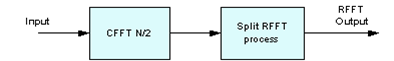
As can be seen from the above block diagram, the FFT of real number sequence is to calculate N/2 real number CFFT first, and then reshape the data for processing, so as to obtain half of the FFT spectrum (taking advantage of the symmetry of the spectrum after FFT transformation).
The inverse FFT of an N-point real sequence is realized by the following steps:
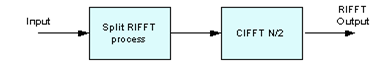
Real FFT supports floating point, Q31 and Q15 data types.
31.3 single precision function arm_ rfft_ fast_ Use of F32 (including amplitude frequency and phase frequency)
31.3.1 function description
Function prototype:
void arm_rfft_fast_f32(
  const arm_rfft_fast_instance_f32 * S,
  float32_t * p,
  float32_t * pOut,
  uint8_t ifftFlag)
Function Description:
This function is used for single precision floating-point real FFT.
Function parameters:
- The first parameter is the encapsulated floating-point FFT instantiation, which requires the user to call the function arm first_ rfft_ fast_ init_ F32 initialization, and then for this function arm_rfft_fast_f32 call. Support 32, 64, 128, 256, 512, 1024, 2048, 4096 point FFT.
For example, 1024 point FFT is performed, and the code is as follows:
arm_rfft_fast_instance_f32 S;
arm_rfft_fast_init_f32(&S, 1024);
arm_rfft_fast_f32(&S, testInput_f32, testOutput_f32, ifftFlag);
- The second parameter is the real address. For example, we need to do 1024 point real FFT to ensure 1024 buffers.
- The third parameter is the FFT conversion result. The conversion result is not a real number, but a complex number, which is arranged in order according to the real part, virtual part, real part and imaginary part. For example, for 1024 point FFT, the output here will also have 1024 data, that is, 512 resets.
- The fourth parameter is used to set forward transformation and inverse transformation. ifftFlag=0 means forward transformation and ifftFlag=1 means inverse transformation.
31.3.2 use examples and compare with Matlab
Next, run this function on the development board and calculate the corresponding amplitude and frequency, and then compare it with the results calculated by Matlab.
/*
*********************************************************************************************************
*    Function name: arm_rfft_f32_app
*    Function Description: call the function arm_rfft_fast_f32 calculate amplitude frequency and phase frequency
*    Formal parameter: None
*    Return value: None
*********************************************************************************************************
*/
static void arm_rfft_f32_app(void)
{
    uint16_t i;
    arm_rfft_fast_instance_f32 S;


    /* Positive transformation */
    ifftFlag = 0;

    /* Initialize parameters in structure S */
     arm_rfft_fast_init_f32(&S, TEST_LENGTH_SAMPLES);

    for(i=0; i<1024; i++)
    {
        /* The waveform is composed of DC component, 50Hz sine wave, waveform sampling rate of 1024 and initial phase of 60 ° */
        testInput_f32[i] = 1 + cos(2*3.1415926f*50*i/1024 + 3.1415926f/3);
    }

    /* 1024 Point real sequence fast FFT */
    arm_rfft_fast_f32(&S, testInput_f32, testOutput_f32, ifftFlag);

    /* For the convenience of following the function arm_ cfft_ By comparing the results of F32 calculation, 1024 sets of modular values and the actual function arm are solved here_ rfft_ fast_ f32
       Only 512 groups were solved
    */
     arm_cmplx_mag_f32(testOutput_f32, testOutputMag_f32, TEST_LENGTH_SAMPLES);


    printf("=========================================\r\n");

    /* Phase frequency */
    PowerPhaseRadians_f32(testOutput_f32, Phase_f32, TEST_LENGTH_SAMPLES, 0.5f);


    /* Amplitude frequency and phase frequency of serial port printing solution */
    for(i=0; i<TEST_LENGTH_SAMPLES; i++)
    {
        printf("%f, %f\r\n", testOutputMag_f32[i], Phase_f32[i]);
    }
}
Run function arm_rfft_f32_app can print out the calculated modulus and phase angle through the serial port. Next, we will compare the modulus and phase angle calculated by Matlab with arm_rfft_fast_f32 calculated for comparison.
Before comparison, you need to load the data printed by the serial port into Matlab and name the array sampledata. The loading method has been explained in the summary of 13.6 in Chapter 13 of the previous tutorial, which will not be repeated here. The code running in MATLAB is as follows:
Fs = 1024;               % sampling rate
N  = 1024;               % Sampling points
n  = 0:N-1;              % Sampling sequence
t  = 0:1/Fs:1-1/Fs;      % time series
f = n * Fs / N;          %Real frequency

%The waveform is composed of DC component, 50 Hz Sine wave sine wave composition
x = 1 + cos(2*pi*50*t + pi/3)   ;
y = fft(x, N);               %Make changes to the original signal FFT Transform
Mag = abs(y);

subplot(2,2,1);
plot(f, Mag);
title('Matlab Calculate amplitude frequency response');
xlabel('frequency');
ylabel('assignment');

subplot(2,2,2);
realvalue = real(y);
imagvalue = imag(y);
plot(f, atan2(imagvalue, realvalue)*180/pi.*(Mag>=200));
title('Matlab Calculate phase frequency response');
xlabel('frequency');
ylabel('phase angle');

subplot(2,2,3);
plot(f, sampledata1);  %draw STM32 Calculated amplitude frequency response
title('STM32 Calculate amplitude frequency response');
xlabel('frequency');
ylabel('assignment');

subplot(2,2,4);
plot(f, sampledata2);   %draw STM32 Calculated phase frequency response
title('STM32 Calculate phase frequency response');
xlabel('frequency');
ylabel('phase angle');
The output results after running Matlab are as follows:
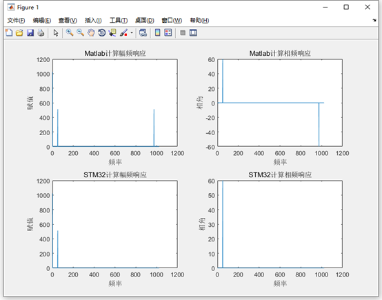
As can be seen from the above comparison results, from the above comparison of the first 512 points, we can see that the calculation results of the two are consistent, Matlab and arm function_ rfft_ fast_ The result of F32 calculation is basically constant. The amplitude obtained from the amplitude frequency response and the initial phase angle obtained from the phase frequency response are all OK.
31.4 double precision function arm_ rfft_ fast_ Use of (including amplitude frequency and phase frequency)
31.4.1 function description
Function prototype:
void arm_rfft_fast_f64(
  arm_rfft_fast_instance_f64 * S,
  float64_t * p,
  float64_t * pOut,
  uint8_t ifftFlag)
Function Description:
This function is used for double precision floating-point real FFT.
Function parameters:
- The first parameter is the encapsulated floating-point FFT instantiation, which requires the user to call the function arm first_ rfft_ fast_ init_ Initialize and then use this function arm_ rfft_ fast_ Call. Support 32, 64, 128, 256, 512, 1024, 2048, 4096 point FFT.
For example, 1024 point FFT is performed, and the code is as follows:
arm_rfft_fast_instance_f64 S;
arm_rfft_fast_init_f64(&S, 1024);
arm_rfft_fast_f64(&S, testInput_f64, testOutput_f64, ifftFlag);
- The second parameter is the real address. For example, we need to do 1024 point real FFT to ensure 1024 buffers.
- The third parameter is the FFT conversion result. The conversion result is not a real number, but a complex number, which is arranged in order according to the real part, virtual part, real part and imaginary part. For example, for 1024 point FFT, the output here will also have 1024 data, that is, 512 resets.
- Ifft0 is used to set the inverse transform parameter, ifft1 = 0 is used to set the inverse transform parameter, and ifft1 = 0 is used to set the inverse transform parameter
31.4.2 use examples and compare with Matlab
Next, run this function on the development board and calculate the corresponding amplitude and frequency, and then compare it with the results calculated by Matlab.
/*
*********************************************************************************************************
*    Function name: arm_rfft_f64_app
*    Function Description: call the function arm_ rfft_ fast_ Calculate amplitude frequency and phase frequency
*    Formal parameter: None
*    Return value: None
*********************************************************************************************************
*/
static void arm_rfft_f64_app(void)
{
    uint16_t i;
    float64_t lX,lY;
    arm_rfft_fast_instance_f64 S;


    /* Positive transformation */
    ifftFlag = 0;

    /* Initialize parameters in structure S */
     arm_rfft_fast_init_f64(&S, TEST_LENGTH_SAMPLES);

    for(i=0; i<1024; i++)
    {
        /* The waveform is composed of DC component, 50Hz sine wave, waveform sampling rate of 1024 and initial phase of 60 ° */
        testInput_f64[i] = 1 + cos(2*3.1415926*50*i/1024 + 3.1415926/3);
    }

    /* 1024 Point real sequence fast FFT */
    arm_rfft_fast_f64(&S, testInput_f64, testOutput_f64, ifftFlag);

    /* Solving modulus  */
    for (i =0; i < TEST_LENGTH_SAMPLES; i++)
    {
         lX = testOutput_f64[2*i];                    /* real part*/
        lY = testOutput_f64[2*i+1];                   /* imaginary part */
        testOutputMag_f64[i] = sqrt(lX*lX+ lY*lY);   /* Seeking module */
    }


    printf("=========================================\r\n");

    /* Phase frequency */
    PowerPhaseRadians_f64(testOutput_f64, Phase_f64, TEST_LENGTH_SAMPLES, 0.5);


    /* Serial port printing amplitude and phase frequency */
    for(i=0; i<TEST_LENGTH_SAMPLES; i++)
    {
        printf("%.11f, %.11f\r\n", testOutputMag_f64[i], Phase_f64[i]);
    }

}
Run function arm_rfft_f64_app can print out the calculated modulus and phase angle through the serial port. Next, we will compare the modulus and phase angle calculated by Matlab with arm_rfft_fast_f32 calculated for comparison.
Before comparison, you need to load the data printed by the serial port into Matlab and name the array sampledata. The loading method has been explained in the summary of 13.6 in Chapter 13 of the previous tutorial, which will not be repeated here. The code running in MATLAB is as follows:
Fs = 1024;               % sampling rate
N  = 1024;               % Sampling points
n  = 0:N-1;              % Sampling sequence
t  = 0:1/Fs:1-1/Fs;      % time series
f = n * Fs / N;          %Real frequency

%The waveform is composed of DC component, 50 Hz Sine wave sine wave composition
x = 1 + cos(2*pi*50*t + pi/3)   ;
y = fft(x, N);               %Make changes to the original signal FFT Transform
Mag = abs(y);

subplot(2,2,1);
plot(f, Mag);
title('Matlab Calculate amplitude frequency response');
xlabel('frequency');
ylabel('assignment');

subplot(2,2,2);
realvalue = real(y);
imagvalue = imag(y);
plot(f, atan2(imagvalue, realvalue)*180/pi.*(Mag>=200));
title('Matlab Calculate phase frequency response');
xlabel('frequency');
ylabel('phase angle');

subplot(2,2,3);
plot(f, sampledata1);  %draw STM32 Calculated amplitude frequency response
title('STM32 Calculate amplitude frequency response');
xlabel('frequency');
ylabel('assignment');

subplot(2,2,4);
plot(f, sampledata2);   %draw STM32 Calculated phase frequency response
title('STM32 Calculate phase frequency response');
xlabel('frequency');
ylabel('phase angle');
The output results after running Matlab are as follows:
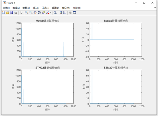
As can be seen from the above comparison results, from the above comparison of the first 512 points, we can see that the calculation results of the two are consistent, Matlab and arm function_ rfft_ fast_ The result of the calculation is basically constant. The amplitude obtained from the amplitude frequency response and the initial phase angle obtained from the phase frequency response are all OK.
31.5 experimental routine description (MDK)
Supporting examples:
V7-221_ Real floating point FTT (supports single precision and double precision)
Purpose of the experiment:
- Learn real floating-point FFT and support single precision floating-point and double precision floating-point
Experiment content:
- Start an automatic software reinstallation timer and turn LED2 every 100ms.
- Press the key K1, and the serial port will print the amplitude frequency response and phase frequency response of 1024 point real number single precision FFT.
- Press the key K2, and the serial port will print the amplitude frequency response and phase frequency response of 1024 point real double precision FFT.
Precautions for using AC6
Pay special attention to the issues in Annex section C
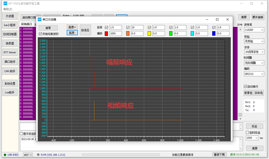
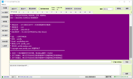
Information printed by serial port after power on:
Baud rate 115200, data bit 8, parity bit none, stop bit 1.
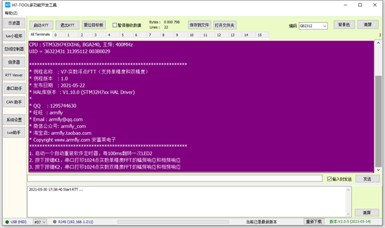
RTT printing information:
Programming:
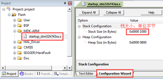
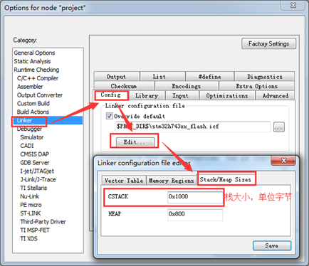
System stack size allocation:
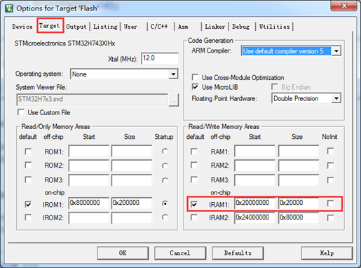
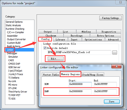
DTCM for RAM space:
Hardware peripheral initialization
The initialization of hardware peripherals is in BSP C file realization:
/*
*********************************************************************************************************
*    Function name: bsp_Init
*    Function Description: initialize all hardware devices. This function configures CPU registers and peripheral registers and initializes some global variables. It only needs to be called once
*    Formal parameter: None
*    Return value: None
*********************************************************************************************************
*/
void bsp_Init(void)
{
    /* Configure MPU */
    MPU_Config();

    /* Enable L1 Cache */
    CPU_CACHE_Enable();

    /*
       STM32H7xx HAL When the library is initialized, the system still uses the 64MHz provided by H7. HSI clock:
       - Call function HAL_InitTick, initialize tick clock interrupt for 1ms.
       - Set the NVIC priority group to 4.
     */
    HAL_Init();

    /*
       Configure the system clock to 400MHz
       - Switch to HSE.
       - This function updates the global variable systemcorelock and reconfigures HAL_InitTick.
    */
    SystemClock_Config();

    /*
       Event Recorder:
       - It can be used for code execution time measurement, mdk5 25 and above, not IAR.
       - It is not enabled by default. If you want to enable this option, please refer to Chapter 8 of the V7 development board user manual
    */
#if Enable_EventRecorder == 1
    /* Initialize the EventRecorder and turn it on */
    EventRecorderInitialize(EventRecordAll, 1U);
    EventRecorderStart();
#endif

    bsp_InitKey();        /* The key initialization should be placed before the tick timer, because the button detection is scanned by the tick timer */
    bsp_InitTimer();      /* Initialize tick timer */
    bsp_InitUart();    /* Initialize serial port */
    bsp_InitExtIO();    /* Initialize FMC bus 74HC574 extension IO Must be in BSP_ Execute before initled() */
    bsp_InitLed();        /* Initialize LED */
}
MPU configuration and Cache configuration:
Both data Cache and instruction Cache are enabled. The AXI SRAM area is configured (AXI SRAM is not used in this example) and the extended IO area of FMC.
/*
*********************************************************************************************************
*    Function name: MPU_Config
*    Function Description: configure MPU
*    Formal parameter: None
*    Return value: None
*********************************************************************************************************
*/
static void MPU_Config( void )
{
    MPU_Region_InitTypeDef MPU_InitStruct;

    /* Disable MPU */
    HAL_MPU_Disable();

    /* Configure the MPU attribute of AXI SRAM as Write back, Read allocate, Write allocate */
    MPU_InitStruct.Enable           = MPU_REGION_ENABLE;
    MPU_InitStruct.BaseAddress      = 0x24000000;
    MPU_InitStruct.Size             = MPU_REGION_SIZE_512KB;
    MPU_InitStruct.AccessPermission = MPU_REGION_FULL_ACCESS;
    MPU_InitStruct.IsBufferable     = MPU_ACCESS_BUFFERABLE;
    MPU_InitStruct.IsCacheable      = MPU_ACCESS_CACHEABLE;
    MPU_InitStruct.IsShareable      = MPU_ACCESS_NOT_SHAREABLE;
    MPU_InitStruct.Number           = MPU_REGION_NUMBER0;
    MPU_InitStruct.TypeExtField     = MPU_TEX_LEVEL1;
    MPU_InitStruct.SubRegionDisable = 0x00;
    MPU_InitStruct.DisableExec      = MPU_INSTRUCTION_ACCESS_ENABLE;

    HAL_MPU_ConfigRegion(&MPU_InitStruct);


    /* Configure the MPU attribute of FMC extension IO as Device or Strongly Ordered */
    MPU_InitStruct.Enable           = MPU_REGION_ENABLE;
    MPU_InitStruct.BaseAddress      = 0x60000000;
    MPU_InitStruct.Size             = ARM_MPU_REGION_SIZE_64KB;
    MPU_InitStruct.AccessPermission = MPU_REGION_FULL_ACCESS;
    MPU_InitStruct.IsBufferable     = MPU_ACCESS_BUFFERABLE;
    MPU_InitStruct.IsCacheable      = MPU_ACCESS_NOT_CACHEABLE;
    MPU_InitStruct.IsShareable      = MPU_ACCESS_NOT_SHAREABLE;
    MPU_InitStruct.Number           = MPU_REGION_NUMBER1;
    MPU_InitStruct.TypeExtField     = MPU_TEX_LEVEL0;
    MPU_InitStruct.SubRegionDisable = 0x00;
    MPU_InitStruct.DisableExec      = MPU_INSTRUCTION_ACCESS_ENABLE;

    HAL_MPU_ConfigRegion(&MPU_InitStruct);

    /*Enable MPU */
    HAL_MPU_Enable(MPU_PRIVILEGED_DEFAULT);
}

/*
*********************************************************************************************************
*    Function name: CPU_CACHE_Enable
*    Function Description: enable L1 Cache
*    Formal parameter: None
*    Return value: None
*********************************************************************************************************
*/
static void CPU_CACHE_Enable(void)
{
    /* Enable I-Cache */
    SCB_EnableICache();

    /* Enable D-Cache */
    SCB_EnableDCache();
}
Main functions:
The main program realizes the following operations:
- Start an automatic software reinstallation timer and turn LED2 every 100ms.
- Press the key K1, and the serial port will print the amplitude frequency response and phase frequency response of 1024 point real number single precision FFT.
- Press the key K2, and the serial port will print the amplitude frequency response and phase frequency response of 1024 point real double precision FFT.
/*
*********************************************************************************************************
*    Function name: main
*    Function Description: c program entry
*    Formal parameter: None
*    Return value: error code (no processing required)
*********************************************************************************************************
*/
int main(void)
{
    uint8_t ucKeyCode;        /* Key code */


    bsp_Init();        /* Hardware initialization */
    PrintfLogo();    /* Print routine information to serial port 1 */

    PrintfHelp();    /* Print operation tips */


    bsp_StartAutoTimer(0, 100);    /* Start a 100ms timer for automatic reassembly */

    /* Enter the main program loop body */
    while (1)
    {
        bsp_Idle();        /* This function is in BSP C documents. Users can modify this function to realize CPU sleep and dog feeding */


        if (bsp_CheckTimer(0))    /* Judge timer timeout */
        {
            /* Come in every 100ms */
            bsp_LedToggle(4);    /* Flip the status of LED2 */
        }

        ucKeyCode = bsp_GetKey();    /* Read the key value and return to key when no key is pressed_ NONE = 0 */
        if (ucKeyCode != KEY_NONE)
        {
            switch (ucKeyCode)
            {
                case KEY_DOWN_K1:            /* K1 Key press */
                    arm_rfft_f32_app();
                    break;

                case KEY_DOWN_K2:            /* K2 Key press */
                    arm_rfft_f64_app();
                    break;


                default:
                    /* Other key values are not processed */
                    break;
            }
        }

    }
}
31.6 experimental routine description (IAR)
Supporting examples:
V7-221_ Real floating point FTT (supports single precision and double precision)
Purpose of the experiment:
- Learn real floating-point FFT and support single precision floating-point and double precision floating-point
Experiment content:
- Start an automatic software reinstallation timer and turn LED2 every 100ms.
- Press the key K1, and the serial port will print the amplitude frequency response and phase frequency response of 1024 point real number single precision FFT.
- Press the key K2, and the serial port will print the amplitude frequency response and phase frequency response of 1024 point real double precision FFT.
Information printed by serial port after power on:
Baud rate 115200, data bit 8, parity bit none, stop bit 1.

RTT printing information:
Programming:
System stack size allocation:
DTCM for RAM space:
Hardware peripheral initialization
The initialization of hardware peripherals is in BSP C file realization:
/*
*********************************************************************************************************
*    Function name: bsp_Init
*    Function Description: initialize all hardware devices. This function configures CPU registers and peripheral registers and initializes some global variables. It only needs to be called once
*    Formal parameter: None
*    Return value: None
*********************************************************************************************************
*/
void bsp_Init(void)
{
    /* Configure MPU */
    MPU_Config();

    /* Enable L1 Cache */
    CPU_CACHE_Enable();

    /*
       STM32H7xx HAL When the library is initialized, the system still uses the 64MHz provided by H7. HSI clock:
       - Call function HAL_InitTick, initialize tick clock interrupt for 1ms.
       - Set the NVIC priority group to 4.
     */
    HAL_Init();

    /*
       Configure the system clock to 400MHz
       - Switch to HSE.
       - This function updates the global variable systemcorelock and reconfigures HAL_InitTick.
    */
    SystemClock_Config();

    /*
       Event Recorder:
       - It can be used for code execution time measurement, mdk5 25 and above, not IAR.
       - It is not enabled by default. If you want to enable this option, please refer to Chapter 8 of the V7 development board user manual
    */
#if Enable_EventRecorder == 1
    /* Initialize the EventRecorder and turn it on */
    EventRecorderInitialize(EventRecordAll, 1U);
    EventRecorderStart();
#endif

    bsp_InitKey();        /* The key initialization should be placed before the tick timer, because the button detection is scanned by the tick timer */
    bsp_InitTimer();      /* Initialize tick timer */
    bsp_InitUart();    /* Initialize serial port */
    bsp_InitExtIO();    /* Initialize FMC bus 74HC574 extension IO Must be in BSP_ Execute before initled() */
    bsp_InitLed();        /* Initialize LED */
}
MPU configuration and Cache configuration:
Both data Cache and instruction Cache are enabled. The AXI SRAM area is configured (AXI SRAM is not used in this example) and the extended IO area of FMC.
/*
*********************************************************************************************************
*    Function name: MPU_Config
*    Function Description: configure MPU
*    Formal parameter: None
*    Return value: None
*********************************************************************************************************
*/
static void MPU_Config( void )
{
    MPU_Region_InitTypeDef MPU_InitStruct;

    /* Disable MPU */
    HAL_MPU_Disable();

    /* Configure the MPU attribute of AXI SRAM as Write back, Read allocate, Write allocate */
    MPU_InitStruct.Enable           = MPU_REGION_ENABLE;
    MPU_InitStruct.BaseAddress      = 0x24000000;
    MPU_InitStruct.Size             = MPU_REGION_SIZE_512KB;
    MPU_InitStruct.AccessPermission = MPU_REGION_FULL_ACCESS;
    MPU_InitStruct.IsBufferable     = MPU_ACCESS_BUFFERABLE;
    MPU_InitStruct.IsCacheable      = MPU_ACCESS_CACHEABLE;
    MPU_InitStruct.IsShareable      = MPU_ACCESS_NOT_SHAREABLE;
    MPU_InitStruct.Number           = MPU_REGION_NUMBER0;
    MPU_InitStruct.TypeExtField     = MPU_TEX_LEVEL1;
    MPU_InitStruct.SubRegionDisable = 0x00;
    MPU_InitStruct.DisableExec      = MPU_INSTRUCTION_ACCESS_ENABLE;

    HAL_MPU_ConfigRegion(&MPU_InitStruct);


    /* Configure the MPU attribute of FMC extension IO as Device or Strongly Ordered */
    MPU_InitStruct.Enable           = MPU_REGION_ENABLE;
    MPU_InitStruct.BaseAddress      = 0x60000000;
    MPU_InitStruct.Size             = ARM_MPU_REGION_SIZE_64KB;
    MPU_InitStruct.AccessPermission = MPU_REGION_FULL_ACCESS;
    MPU_InitStruct.IsBufferable     = MPU_ACCESS_BUFFERABLE;
    MPU_InitStruct.IsCacheable      = MPU_ACCESS_NOT_CACHEABLE;
    MPU_InitStruct.IsShareable      = MPU_ACCESS_NOT_SHAREABLE;
    MPU_InitStruct.Number           = MPU_REGION_NUMBER1;
    MPU_InitStruct.TypeExtField     = MPU_TEX_LEVEL0;
    MPU_InitStruct.SubRegionDisable = 0x00;
    MPU_InitStruct.DisableExec      = MPU_INSTRUCTION_ACCESS_ENABLE;

    HAL_MPU_ConfigRegion(&MPU_InitStruct);

    /*Enable MPU */
    HAL_MPU_Enable(MPU_PRIVILEGED_DEFAULT);
}

/*
*********************************************************************************************************
*    Function name: CPU_CACHE_Enable
*    Function Description: enable L1 Cache
*    Formal parameter: None
*    Return value: None
*********************************************************************************************************
*/
static void CPU_CACHE_Enable(void)
{
    /* Enable I-Cache */
    SCB_EnableICache();

    /* Enable D-Cache */
    SCB_EnableDCache();
}
Main functions:
The main program realizes the following operations:
- Start an automatic software reinstallation timer and turn LED2 every 100ms.
- Press the key K1, and the serial port will print the amplitude frequency response and phase frequency response of 1024 point real number single precision FFT.
- Press the key K2, and the serial port will print the amplitude frequency response and phase frequency response of 1024 point real double precision FFT.
/*
*********************************************************************************************************
*    Function name: main
*    Function Description: c program entry
*    Formal parameter: None
*    Return value: error code (no processing required)
*********************************************************************************************************
*/
int main(void)
{
    uint8_t ucKeyCode;        /* Key code */


    bsp_Init();        /* Hardware initialization */
    PrintfLogo();    /* Print routine information to serial port 1 */

    PrintfHelp();    /* Print operation tips */


    bsp_StartAutoTimer(0, 100);    /* Start a 100ms timer for automatic reassembly */

    /* Enter the main program loop body */
    while (1)
    {
        bsp_Idle();        /* This function is in BSP C documents. Users can modify this function to realize CPU sleep and dog feeding */


        if (bsp_CheckTimer(0))    /* Judge timer timeout */
        {
            /* Come in every 100ms */
            bsp_LedToggle(4);    /* Flip the status of LED2 */
        }

        ucKeyCode = bsp_GetKey();    /* Read the key value and return to key when no key is pressed_ NONE = 0 */
        if (ucKeyCode != KEY_NONE)
        {
            switch (ucKeyCode)
            {
                case KEY_DOWN_K1:            /* K1 Key press */
                    arm_rfft_f32_app();
                    break;

                case KEY_DOWN_K2:            /* K2 Key press */
                    arm_rfft_f64_app();
                    break;


                default:
                    /* Other key values are not processed */
                    break;
            }
        }

    }
}
31.7 summary
This chapter is designed to realize real FFT. Those who are interested can have an in-depth understanding of the implementation of the source code.