catalogue
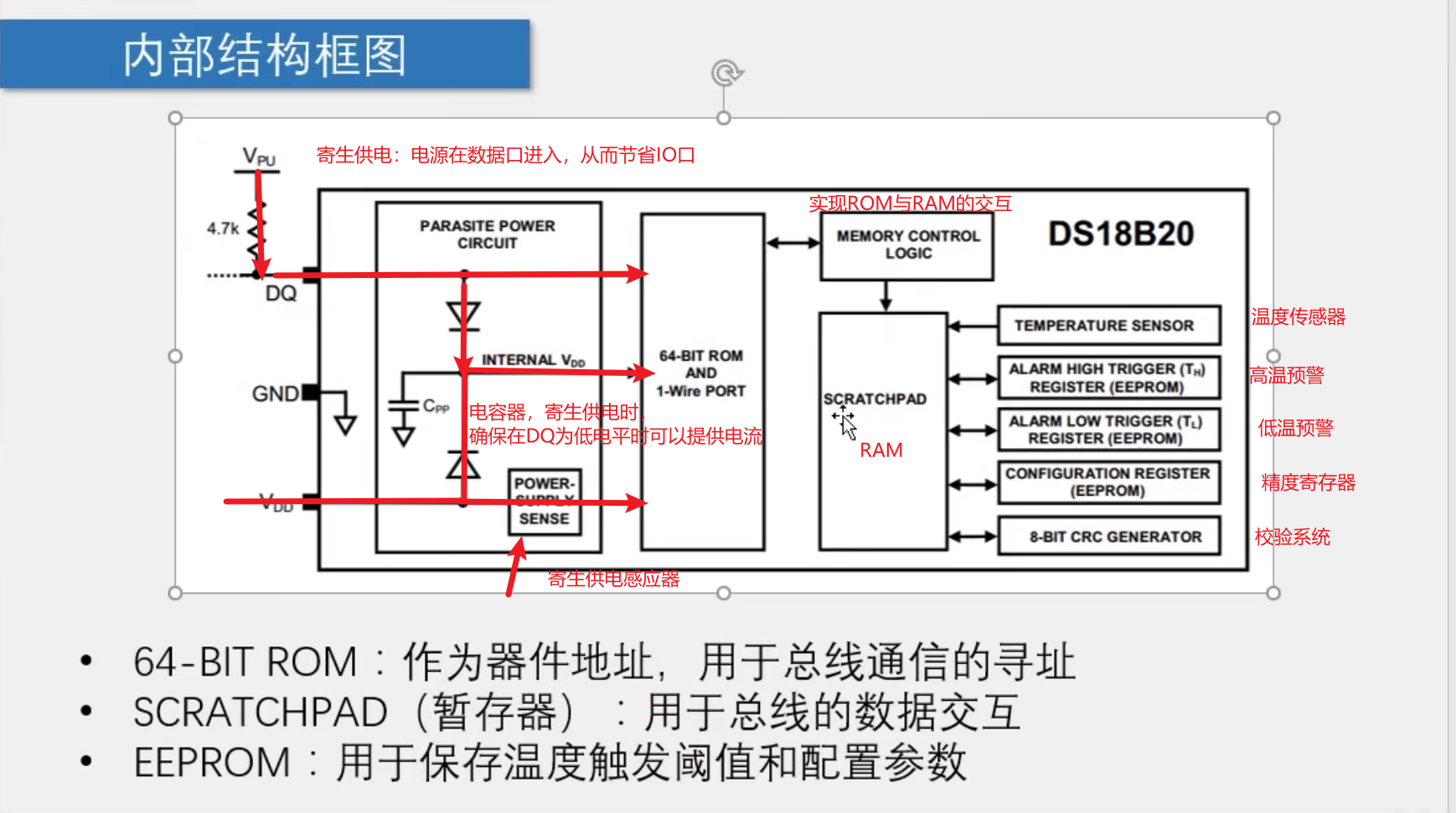
Structure diagram of DS18B20 temperature sensor:
DS18B20 temperature sensor operation configuration:
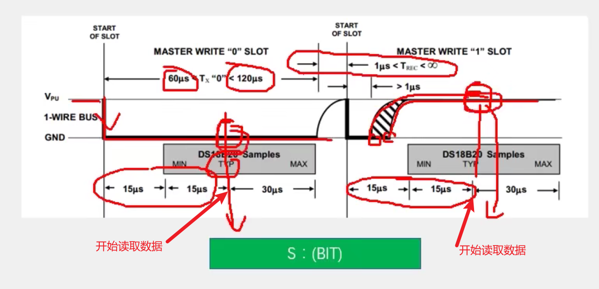
Send one bit: (master to slave)
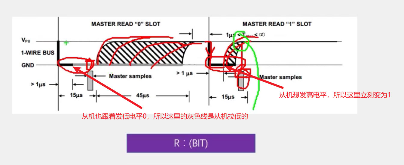
Receive a bit: (slave to host)
Single line communication function:
Introduction to DS18B20
DS18B20 is a common digital temperature sensor. Its control commands and data are input and output in the form of digital signals. Compared with analog temperature sensors, DS18B20 has the characteristics of powerful function, simple hardware, easy expansion and strong anti-interference
Temperature measurement range: - 55 ° C to + 125 ° C
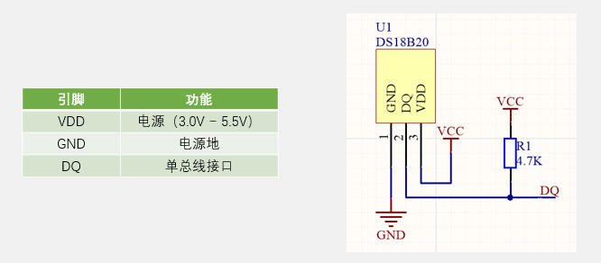
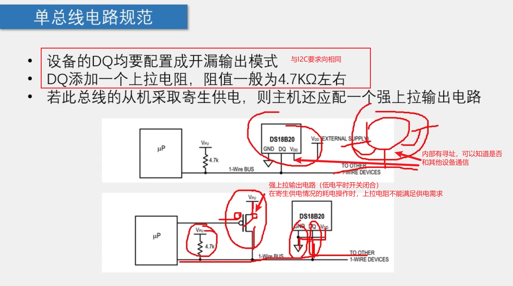
Communication interface: 1-Wire (single bus)
Other features: it can form bus structure, built-in temperature alarm function and parasitic power supply
Structure diagram of DS18B20 temperature sensor:
DS18B20 temperature sensor operation configuration:
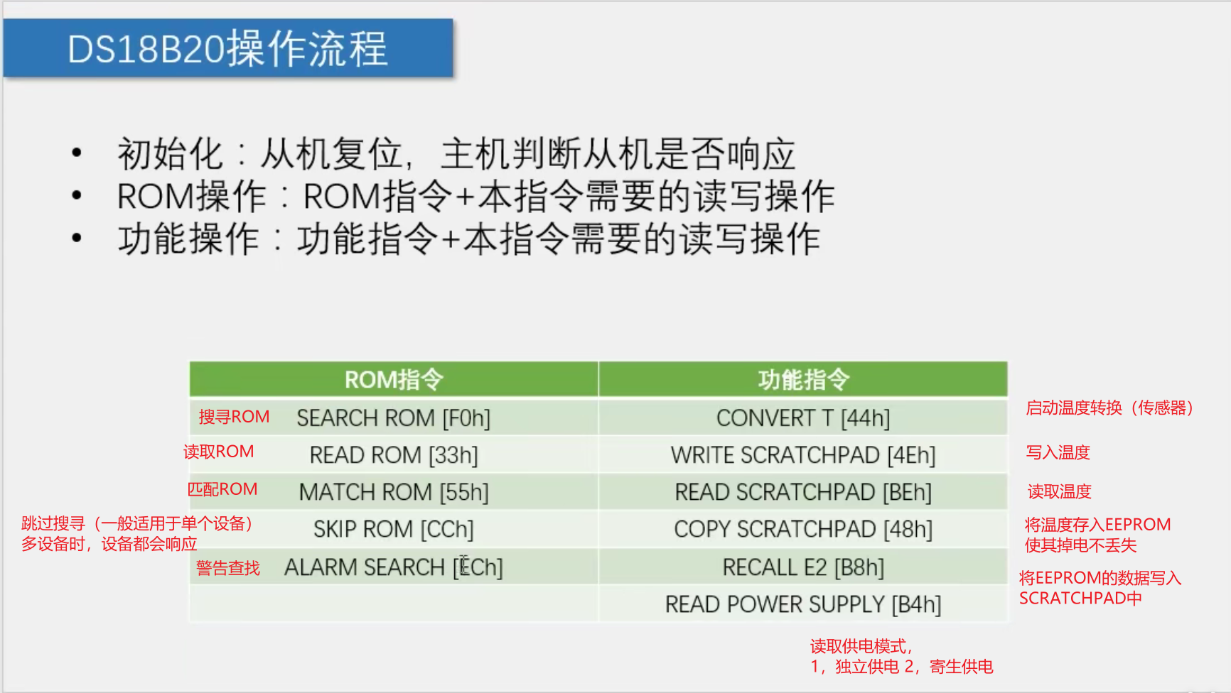
During the initialization of DS18B20 temperature sensor, since we only have DS18B20 device for single line communication here, ROM does not need to be matched, and the analog signal collected by DS18B20 temperature sensor should be converted into temperature value
Therefore, the operation of SKIP ROM (0xCC) and CONVERT T (0x44) is started
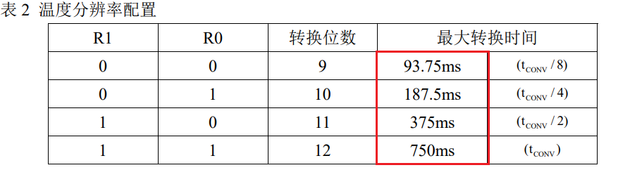
There is a certain time limit during the conversion, that is, the reading can not be carried out after the conversion. Here, the maximum 750ms is taken as the standard, and Delay (1000ms) is recommended
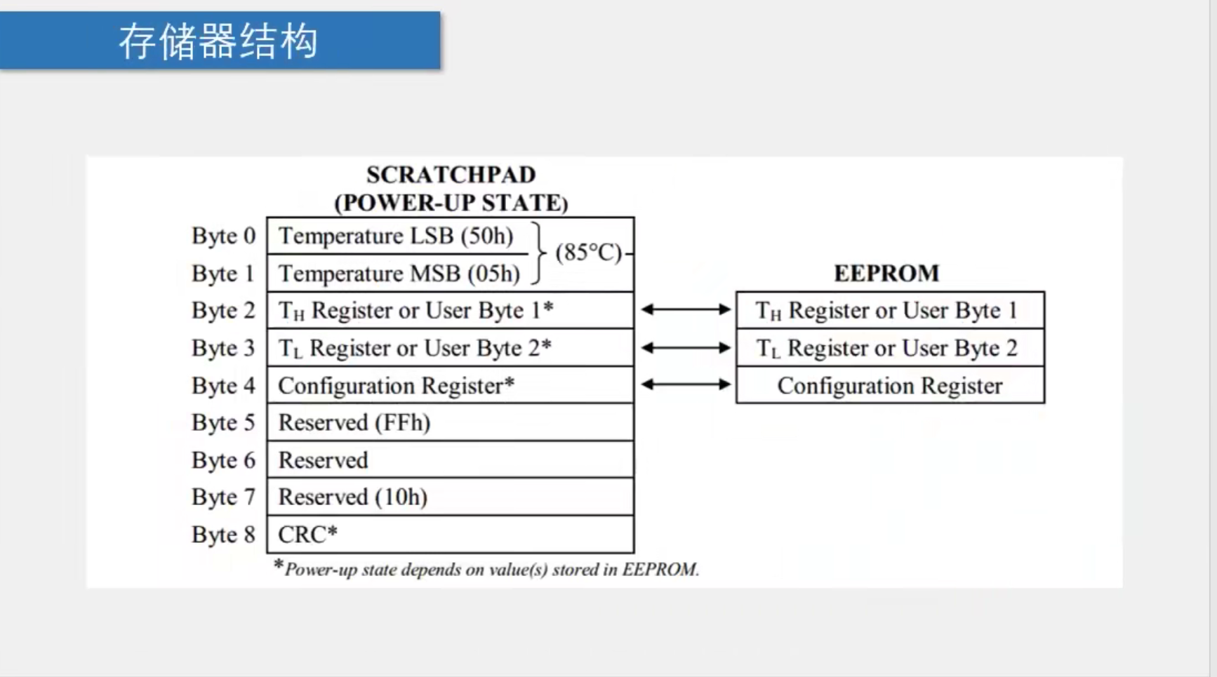
 Finally, read the temperature. READ SCRATCHPAD(0xBE) is used to read the temperature
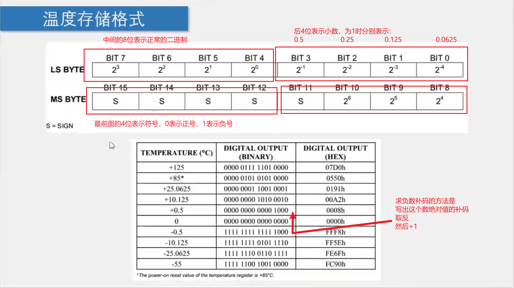
Here, LS BYTE (TMSB) stands for low bit, while MS BYTE (TLSB) stands for low bit, temp = (TMSB < < 8) | TLSB
Here, you need to move the 4 bits of the decimal part to the right to get the floating-point number of the actual temperature, move one bit x2 to the left and one bit / 2 to the right. T=Temp/16.0
Introduction to single bus
1-Wire BUS is a general data bus developed by Dallas company
One communication line: DQ
Asynchronous, half duplex
The single bus only needs one communication line to realize the two-way transmission of data. When parasitic power supply is adopted, the VDD line of the equipment can also be omitted. At this time, power supply and communication only need DQ and GND lines
Parasitic power supply is equivalent to data line, that is, DQ also uses DQ to supply power when transmitting data, so as to save ports
Single bus specification
Single bus timing structure
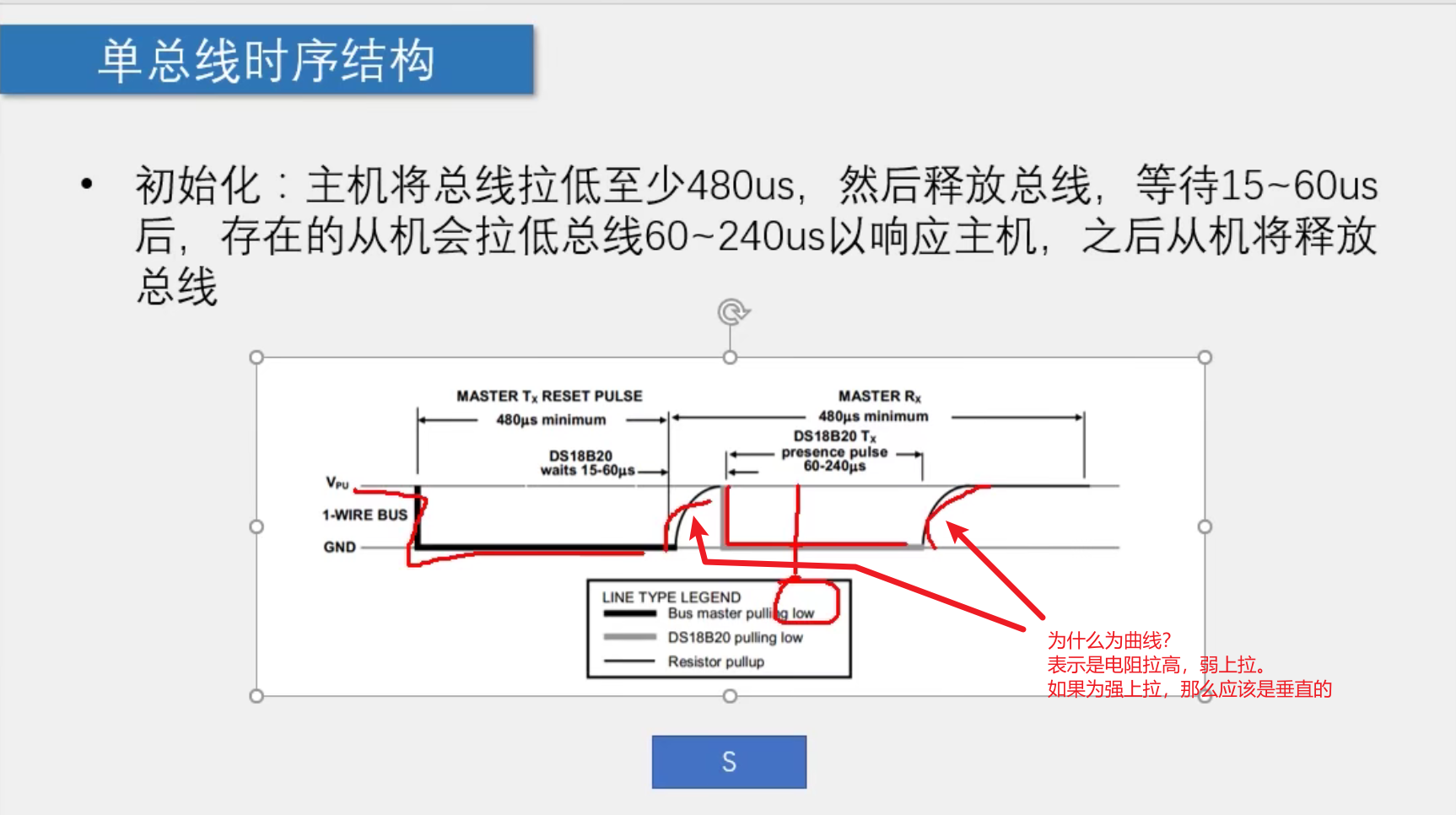
initialization:
The master will lower the bus by at least 480us, and then release the bus. After waiting for 15~60us, the existing slave will lower the bus by 60~240us to respond to the master, and then the slave will release the bus
Send one bit: (master to slave)
The host pulls down the bus by 60~120us, and then releases the bus, indicating that 0 is sent; (confirm that the upper limit is 120us here to avoid taking too long, which means initialization)
The host pulls down the bus by 1~15us, and then releases the bus, indicating that 1 is sent;
The slave will read the level after the bus is pulled down by 30us (typical value), and the whole time slice shall be greater than 60us
(in the design, the initial value can be set at 0us, the value can be assigned at 10us, and then the delay is 50us. This is just the level read during the last delay of 50us)
Receive a bit: (slave to host)
The host pulls the bus down by 1~15us, then releases the bus, and reads the bus level within 15us after pulling down (close to the end of 15us as far as possible). If it is read as low level, it is received 0, if it is read as high level, it is received 1, and the whole time slice should be greater than 60us
(in the design, you can first set it to 0 at 0us, then set it to 1 at 5us, delay 5us to see whether the slave pulls down the bus, then read the level, and finally delay 50us to end). Here, pull up the bus to 1 at the first 5us to make the effect obvious. It is also possible to set 0 in the figure
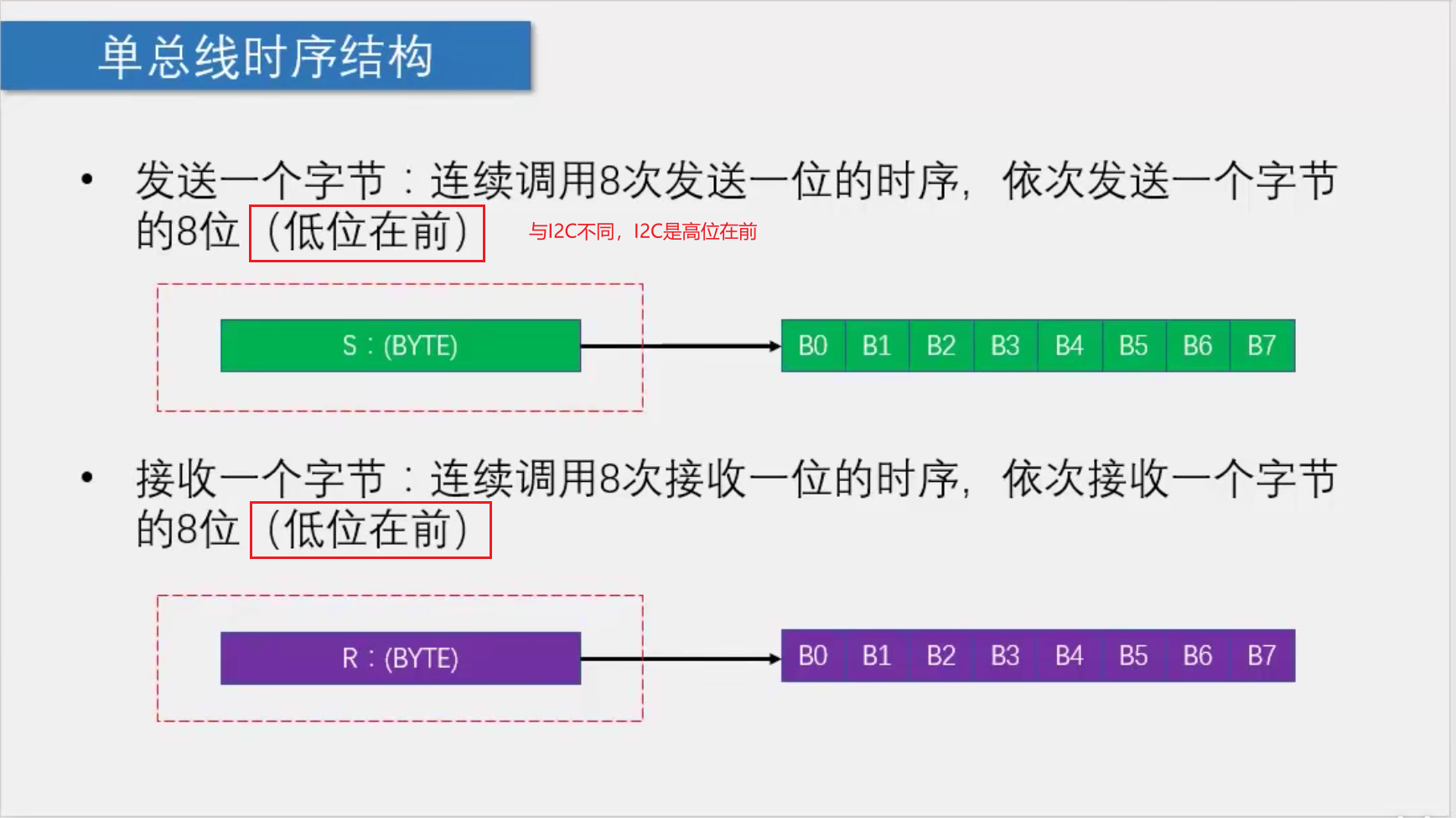
Send a byte:
Call the sequence of sending one bit for 8 consecutive times, and send 8 bits of one byte in turn (the low order is the first)
Generally, the "&" operation of 8 cycles is used to assign data to DQ in turn
Receive a byte:
Call the sequence of receiving one bit for 8 consecutive times, and receive 8 bits of one byte in turn (the low order is the first)
Generally, the "|" operation of 8 cycles is used to read the data to the intermediate variables in turn
Code example:
main function:
#include <REGX52.H>
#include "LCD1602.h"
#include "DS18B20.h"
#include "Delay.h"

float T;
extern unsigned char TLSB,TMSB;
void main()
{
	DS18B20_ConvertT();		//Switch the temperature once before power on to prevent the first reading from being the default value and the screen from flashing
	Delay(1000);			//Wait for the conversion to complete
	LCD_Init();
	LCD_ShowString(1,1,"BIN:");
	while(1)
	{
		DS18B20_ConvertT();	//Conversion temperature
		T=DS18B20_ReadT();	//Read temperature
		if(T<0)				//If the temperature is less than 0
		{
			LCD_ShowChar(2,1,'-');	//Show negative sign
			T=-T;			//Change the temperature to a positive number
		}
		else				//If the temperature is greater than or equal to 0
		{
			LCD_ShowChar(2,1,'+');	//Show positive sign
		}
		LCD_ShowNum(2,2,T,3);		//Display temperature integer part
		LCD_ShowChar(2,5,'.');		//Show decimal point
		LCD_ShowNum(2,6,(unsigned long)(T*10000)%10000,4);//(T*10000) the integer and decimal parts of the displayed temperature exceed 65536, so it is defined as unsigned long
    LCD_ShowBinNum(1,5,TMSB,4);                       //%10000 is the last four digits
    LCD_ShowBinNum(1,9,TLSB,8);
	}

}
Single line communication function:
#include <REGX52.H>

//Pin definition
sbit OneWire_DQ=P3^7;

/**
  * @brief  Single bus initialization
  * @param  nothing
  * @retval Slave response bit, 0 for response and 1 for non response
  */
unsigned char OneWire_Init(void)
{
	unsigned char i;
	unsigned char AckBit;
	OneWire_DQ=1;
	OneWire_DQ=0;
	i = 247;while (--i);//Delay 500us calls the function in a relatively small time, so the error of calling the function is relatively large
	OneWire_DQ=1;
	i = 32;while (--i);//Delay 70us
	AckBit=OneWire_DQ;
	i = 247;while (--i);//Delay 500us will finish the sequence
	return AckBit;//Reply bit
}

void OneWire_SendBit(unsigned char Bit)
{
	unsigned char i;
	OneWire_DQ=0;
	i = 4;while (--i);			//Delay 10us
	OneWire_DQ=Bit;
	i = 24;while (--i);			//Delay 50us slave reads level at 30us
	OneWire_DQ=1;
}

unsigned char OneWire_ReceiveBit(void)
{
	unsigned char i;
	unsigned char Bit;
	OneWire_DQ=0;
	i = 2;while (--i);			//Release after 5us delay
	OneWire_DQ=1;
	i = 2;while (--i);			//Delay 5us waiting for bus change
	Bit=OneWire_DQ;
	i = 24;while (--i);			//Delay 50us ensure total time > 60us
	return Bit;
}

void OneWire_SendByte(unsigned char Byte)
{
	unsigned char i;
	for(i=0;i<8;i++)
	{
		OneWire_SendBit(Byte&(0x01<<i));
	}
}

unsigned char OneWire_ReceiveByte(void)
{
	unsigned char i;
	unsigned char Byte=0x00;
	for(i=0;i<8;i++)
	{
		if(OneWire_ReceiveBit()){Byte|=(0x01<<i);}
	}
	return Byte;
}
DS18B20 temperature sensor function:
#include <REGX52.H>
#include "OneWire.h"

//DS18B20 instruction
#define DS18B20_SKIP_ROM			0xCC
#define DS18B20_CONVERT_T			0x44
#define DS18B20_READ_SCRATCHPAD 	0xBE


void DS18B20_ConvertT(void)
{
	OneWire_Init();
	OneWire_SendByte(DS18B20_SKIP_ROM);
	OneWire_SendByte(DS18B20_CONVERT_T);
}

unsigned char TLSB,TMSB;
float DS18B20_ReadT(void)
{
	//Although unsigned char is unsigned, negative numbers are stored in the form of complement, so if it is assigned to a signed number, the symbol will still be displayed
	int Temp;
	float T;
	OneWire_Init();
	OneWire_SendByte(DS18B20_SKIP_ROM);
	OneWire_SendByte(DS18B20_READ_SCRATCHPAD);
	TLSB=OneWire_ReceiveByte();//Read low
	TMSB=OneWire_ReceiveByte();//Read high
	Temp=(TMSB<<8)|TLSB;
	T=Temp/16.0;//Move the 4 bits of the decimal part to the right to obtain the actual temperature, move one bit x2 to the left and one bit / 2 to the right
	return T;
}
LCD1602 function:
#include <REGX52.H>

//Pin configuration:
sbit LCD_RS=P2^6;
sbit LCD_RW=P2^5;
sbit LCD_EN=P2^7;
#define LCD_DataPort P0

void LCD_Delay()
{
	unsigned char i, j;

	i = 2;
	j = 239;
	do
	{
		while (--j);
	} while (--i);
}

void LCD_WriteCommand(unsigned char Command)
{
	LCD_RS=0;
	LCD_RW=0;
	LCD_DataPort=Command;
	LCD_EN=1;
	LCD_Delay();
	LCD_EN=0;
	LCD_Delay();
}

void LCD_WriteData(unsigned char Data)
{
	LCD_RS=1;
	LCD_RW=0;
	LCD_DataPort=Data;
	LCD_EN=1;
	LCD_Delay();
	LCD_EN=0;
	LCD_Delay();
}

void LCD_SetCursor(unsigned char Line,unsigned char Column)
{
	if(Line==1)
	{
		LCD_WriteCommand(0x80|(Column-1));
	}
	else if(Line==2)
	{
		LCD_WriteCommand(0x80|(Column-1+0x40));
	}
}

void LCD_Init()
{
	LCD_WriteCommand(0x38);//Eight bit data interface, two line display, 5 * 7 dot matrix
	LCD_WriteCommand(0x0c);//Display on, cursor off, flashing off
	LCD_WriteCommand(0x06);//After the data reading and writing operation, the cursor will automatically add one and the screen will not move
	LCD_WriteCommand(0x01);//Cursor reset, screen clearing
}

void LCD_ShowChar(unsigned char Line,unsigned char Column,char Char)
{
	LCD_SetCursor(Line,Column);
	LCD_WriteData(Char);
}

void LCD_ShowString(unsigned char Line,unsigned char Column,char *String)
{
	unsigned char i;
	LCD_SetCursor(Line,Column);
	for(i=0;String[i]!='\0';i++)
	{
		LCD_WriteData(String[i]);
	}
}

int LCD_Pow(int X,int Y)
{
	unsigned char i;
	int Result=1;
	for(i=0;i<Y;i++)
	{
		Result*=X;
	}
	return Result;
}

void LCD_ShowNum(unsigned char Line,unsigned char Column,unsigned int Number,unsigned char Length)
{
	unsigned char i;
	LCD_SetCursor(Line,Column);
	for(i=Length;i>0;i--)
	{
		LCD_WriteData(Number/LCD_Pow(10,i-1)%10+'0');
	}
}
Delay function:
void Delay(unsigned int xms)
{
	unsigned char i, j;
	while(xms--)
	{
		i = 2;
		j = 239;
		do
		{
			while (--j);
		} while (--i);
	}
}