Article catalogue
1, Problem description
Three dimensional reconstruction aims to represent three-dimensional objects as mathematical models that are easy to deal with in computer. In recent years, due to the rapid development of computer hardware, it has been widely used in the fields of automatic driving, VR / AR, medical treatment, digital protection of ancient buildings and so on. Among them, point cloud data, as the most commonly used mathematical model, refers to the collection of a set of vectors in a three-dimensional coordinate system. These vectors are usually expressed in the form of X, Y and Z three-dimensional coordinates, which usually represent the outer surface geometry of an object. In addition, point cloud data can also be attached with RGB information, that is, the color information of each coordinate point, or other information. Depth cameras are usually used to obtain scene depth information. Active sensors based on Kinect generation I and II and passive sensors based on Realsense D435 are widely used. Starting from the active RGBD sensor, this paper introduces the pinhole camera model and the ranging principle of RGBD camera respectively, and realizes the PCD generation of point cloud based on a pair of matched RGBD images in TUM data set.
2, Sensor model
1. Pinhole camera model
The two-dimensional camera maps the three-dimensional coordinate points to the two-dimensional image plane. The pinhole camera model is the most commonly used and effective model. It describes the transformation relationship between the representation of three-dimensional coordinate points in the camera coordinate system and pixel coordinate system. Its schematic and mathematical representation are as follows:

pinhole camera model
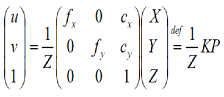
Mathematical model
Where, (u,v) and (X,Y,Z) respectively represent the coordinates of the spatial point in the pixel coordinate system and the camera coordinate system. The matrix in the middle of the formula is called the internal parameter matrix K of the camera. According to the formula, the depth of the point is lost in the projection process, that is, the three-dimensional spatial coordinates of the point cannot be derived from the pixel coordinates in the two-dimensional image and the internal parameters of the camera, Therefore, it is necessary to combine depth ranging and binocular ranging technology to obtain depth information.
2. Depth ranging
RGBD camera uses depth ranging technology to obtain the distance information between spatial points and camera coordinate system and generate depth image. At the same time, it combines sensor calibration technology to align color image and depth image, so as to facilitate the subsequent application of point cloud generation and positioning mapping. According to the principle, the current RGBD cameras can be divided into the infrared structured light principle camera represented by Kinect generation 1 and the time of flight (TOF) principle camera represented by Kinect generation 2.
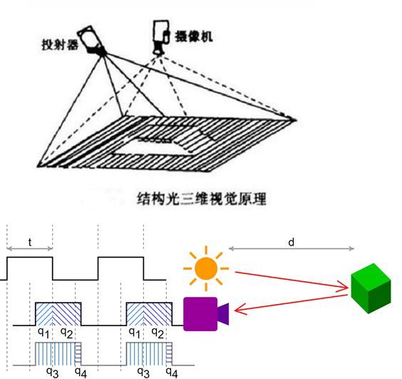
Infrared structured light ranging
No matter what type of ranging principle, RGB-D camera needs to emit a beam of light to the detection target. The difference is that the structured light camera calculates the distance of the object through the returned structured light pattern, while the TOF camera senses the depth according to the flight time of the pulsed light from the emission to the return beam.
code implementation
The code implementation environment of this paper is Ubuntu 18.04 + OpenCV 3.4.13 + PCL 1.12.1 + CMake 3.10.2. A frame of point cloud data is generated based on the RGBD image in the TUM dataset. The download address of the TUM dataset is:
Computer Vision Group - Dataset Download (tum.de) https://vision.in.tum.de/data/datasets/rgbd-dataset/download The corresponding color map and depth map file is 1341841599.918690 under fr3/cabinet sequence PNG and 1341841599.918730 png.
Algorithm steps:
1. Read color map, depth map and camera internal reference
2. Traverse each pixel in the depth map and convert it into three-dimensional coordinates in the camera coordinate system through internal parameters
3. Assign the corresponding RGB value to each 3D coordinate
4. Save the 3D space point set as pcd format data
Note: since the RGBD in the TUM dataset has been registered, the coordinate system and resolution of the image are consistent, and no additional pixel matching is required.
#include <iostream>
#include <opencv2/core/core.hpp>
#include <opencv2/highgui/highgui.hpp>
#include <pcl/point_types.h>
#include <pcl/io/pcd_io.h>
using namespace std;

int main( int argc, char** argv )
{
    // data fetch
    cv::Mat rgb, depth;
    rgb = cv::imread("../data/rgb.png");
    depth = cv::imread("../data/depth.png", -1);

    // Zoom factor in camera
    double cx = 319.5;
    double cy = 239.5;
    double fx = 525.0;
    double fy = 525.0;
    double depthScale = 5000.0;

    // Define the format used by the point cloud: XYZRGB is used here
    typedef pcl::PointXYZRGB PointT;
    typedef pcl::PointCloud<PointT> PointCloud;

    // Calculate the XYZRGB value corresponding to each point
    PointCloud::Ptr pointCloud(new PointCloud);
    for ( int v=0; v<rgb.rows; v++ )
        for (int u=0; u<rgb.cols; u++)
        {
            unsigned int d = depth.ptr<unsigned short>(v)[u];
            if (d==0)
                continue;
            PointT p;
            p.z = double(d)/depthScale;
            p.x = (u-cx)*p.z/fx;
            p.y = (v-cy)*p.z/fy;
            p.b = rgb.data[v*rgb.step+u*rgb.channels()];
            p.g = rgb.data[v*rgb.step+u*rgb.channels()+1];
            p.r = rgb.data[v*rgb.step+u*rgb.channels()+2];
            pointCloud->points.push_back(p);
        }

    // Point cloud save
    pointCloud->is_dense = false;
    cout << "Common cloud point" << pointCloud->size() << "Point." << endl;
    pcl::io::savePCDFileBinary("../data/cabinet.pcd", *pointCloud );
    return 0;
}
rgbd2pcd.cpp
# cmake version and project name
cmake_minimum_required( VERSION 2.8 )
project( rgbd2pcd )

# Set up opencv Library
find_package( OpenCV REQUIRED )
include_directories( ${OpenCV_INCLUDE_DIRS} )

# Set up pcl Library
find_package( PCL REQUIRED)
include_directories( ${PCL_INCLUDE_DIRS} )

# Compiling and linking
add_executable( rgbd2pcd rgbd2pcd.cpp )
target_link_libraries( rgbd2pcd ${OpenCV_LIBS} ${PCL_LIBRARIES} )
CMakeLists.txt
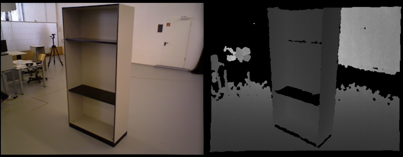
RGBD
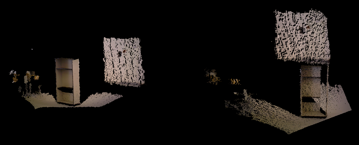
3D point cloud
In terms of effect, due to the influence of visual blind areas and invalid points, single frame point cloud data will produce more holes. If you need to generate dense scene point cloud data, you need to splice and post process the multi frame point cloud. Because the coordinate systems of different frame data are different, accurate camera pose representation also plays a vital role.
summary
In this paper, a frame of point cloud data is generated through camera model conversion and pixel matching based on the latest color map and depth map of a pair of time stamps in TUM data set. In addition to depth ranging, binocular vision is also one of the commonly used ranging methods. The generation of single frame point cloud based on binocular vision will be updated later.
Reference articles
[1] Chapter 5: visual SLAM Lecture 14