Introduction before chapter
This chapter focuses on the basic concept of switch, spanning tree protocol STP, content of switch table, switch configuration, switch mode, switch VLAN configuration, virtual LAN technology and switch STP configuration
Test point 1: basic concept of switch
1. Basic concepts
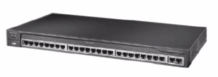
LAN switch is a network connection device that completes the function of forwarding data frames based on MAC address identification. It works in the data link layer and filters and forwards the data frame according to the MAC address in the data frame of the entry port (which is also the working principle of the switch). As the convergence center, the switch can connect multiple data terminal devices together to form a star shaped network.
2. Basic functions:
- Establish and maintain a switching table representing the corresponding relationship between MAC address and switch port
- Establish a virtual connection between the sending node and the receiving node [that is, establish a virtual connection between the switch port (source port) connected by the sender and the switch port (destination port) connected by the receiver]
- Complete the forwarding or filtering of data frames
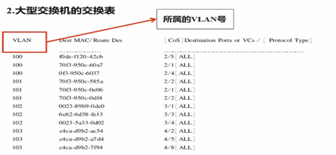
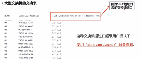
Test site 2: contents of exchange form
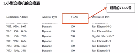
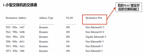
The switching table mainly includes the destination MAC address, the switch port number corresponding to the destination MAC address and the virtual subnet to which it belongs. The virtual subnet is identified by VLAN ID.
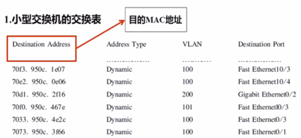
The switch can be viewed by using the "show MAC address table" command in super user mode.
Test point 3: switching mode of switch
1. Classification of exchange mode
The most commonly used switching mode of switch is dynamic switching mode. Dynamic switching mode mainly includes store and forward mode and through mode, and through mode also includes fast forwarding switching and fragment discarding switching.
To sum up, the switch mainly has three switching modes: fast forwarding, fragment discarding and store and forward.
2. Fast forwarding switching mode
Fast forwarding switching mode, also known as through switching mode, is to forward the data frame immediately after the switch receives the first 14 bytes of the frame, that is, the destination address of 6 bytes in the frame. The switching mode will start forwarding before the whole data frame arrives.
The advantages of fast forwarding switching mode are short port switching time, small delay and fast switching speed; The disadvantage is that error detection and correction, speed matching and flow control cannot be carried out, and the reliability is poor. Therefore, it is suitable for small switches.
3. Fragment discard exchange mode
The fragment discarding exchange mode is also known as the non segmented exchange mode. This switching mode is to filter out the conflict pieces that cause most datagram errors before forwarding data frames. When forwarding data, the switch using this switching mode first checks whether the length of the data packet is enough 64 bytes. If the length of the frame is less than 64, it is regarded as a fragment and directly discarded by the switch; Any data frame larger than 64 bytes is regarded as a valid frame by the switch and forwarded; The advantage of fragment discarding switching mode is that it filters out conflict fragments and improves the efficiency of network speed transmission and bandwidth utilization.
4. Store and forward switching mode
The store and forward switching mode saves the whole received data frame in the buffer, and then checks the cyclic redundancy code. After processing the wrong data frame, the destination address of the data frame is taken out for forwarding operation. The disadvantage of store and forward switching mode is that it has large delay in data processing and relatively slow switching speed. However, it can check the link error of data frames, has high reliability, and can effectively improve the network performance; At the same time, it can support ports with different rates and maintain the cooperation between high-speed ports and low-speed ports.
Test site 4: virtual LAN technology
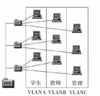
1. Basic concept of VLAN
Virtual network VLAN is based on switched network, which divides the user's terminal equipment into several logical working groups, and each logical working group is a VLAN.
2. Characteristics of VLAN
- VLAN works at the data link layer, which is the second layer of OSI reference model.
- Broadcast information can only be sent to other VLAN members in this VLAN. Broadcast information can only be sent to other VLAN members in this VLAN.
- A VLAN is an independent logical network. Each VLAN has a unique subnet number. Hosts in different VLANs must communicate with each other through routers or layer-3 switches.
3. Identification of VLAN
VLANs are usually identified by VLAN ID (VLAN number) and VLAN name (VLAN name).
IEEE 802.1Q protocol stipulates that VLAN ID is represented by 12 bit s and can support 4096 VLANs.
Among them, 1 ~ 1005 is the standard range, 1006 ~ 1024 is the reserved range, and 1025 ~ 4096 is the extended range. However, not all switches can support 4096 VLANs. Some switches only support the standard range of 1 ~ 1005, in which the VLAN ID that can be used for Ethernet is 1 ~ 1000, and 1002 ~ 1005 is the VLAN ID used by FDDI and token ring network.
VLAN name is represented by 32 characters, which can be letters and numbers. If no name is given when creating a VLAN, the system will automatically give the name according to the default method. The default is VLAN00xxx ("xxx" is the VLAN ID of the VLAN). If the VLAN ID is 100, the default VLAN name is VLAN00100.
Test tree generation protocol: ST5
1. Basic concept of STP
- Spanning tree protocol (STP) is a two-layer link management protocol. Its main function is to provide redundant paths in the second layer link on the basis of ensuring that there is no loop in the network, so as to ensure the reliable and stable operation of the network.
- IEEE 802.1D is the earliest STP standard. It provides dynamic redundancy switching mechanism. It is the most popular and widely used STP standard at present.
- STP runs on switches and bridge equipment and establishes a stable tree structure network through calculation to avoid the generation of loops in the network.
2. Working principle of STP
The working process of STP is to transfer the bridge protocol data unit (BPDU) between switches and compare it with the spanning tree algorithm (STA).
- First, select the root bridge (the root bridge is the core of the whole spanning tree topology, and all data transmission is through the root bridge);
- Then determine the working state of the redundant link port of the switch, and let some ports enter the blocking working mode and others enter the forwarding working mode.
- The port set as blocking mode cannot forward and receive data flow, but it is still an active port for receiving and reading BPDU.
3.BPDU related contents
BPDU carries relevant information about the implementation of spanning tree algorithm, including: Root ID, Root Path Cost, Bridge ID, Port ID., Hello time, Max Age;
- There are two types of BPDU packets: one is the configuration BPDU containing configuration information (no more than 35 bytes), and the other is the topology change notification BPDU containing topology change information (no more than 4 bytes);
- When configuring the Bridge ID information of BPDU package, it is the main basis for selecting the root bridge or root switch;
- Generally, the one with the smallest Bridge ID value becomes the root bridge or root switch;
- The Bridge ID is identified by 8 bytes, the last 6 bytes are the MAC address of the switch, and the first 2 bytes are the priority value;
- The lower the priority value, the higher the priority (root bridge or root switch);
- The priority value range is 0 ~ 61440, and the added value is 4096. The priority of the switch is 32768 by default, which can be set manually by using the command;
- The priority of one switch is set to 8189. Other switches with high priority will become the root switch;
- When selecting the root bridge, the priority is the same, and the root bridge will be determined according to the value of MAC address. The root bridge with the lowest MAC value is the root bridge;
- By default, the switch sends BPDU every 2 seconds. When a network topology change or failure is detected, it will also send a new BPDU and update the spanning tree in time.
Test point 6: switch configuration
1. Configuration mode of switch
- Use the Console port to configure the switch, which is commonly used in the mode adopted when the switch is just delivered and configured for the first time;
- Using Telnet to configure the switch is commonly used in the remote configuration mode. This mode requires that the switch has been connected to the network and the device management address of the switch has been configured
- Use the browser (IE) to configure the switch, which is mainly used to set the switch as a Web server, and then use the browser to configure the switch through any terminal site on the network
2. Configure the system information of the switch
- The basic configuration of the switch is generally completed by using the Console port configuration method. The main contents of the configuration include the host name, super user password, device management address and remote login password of the configured switch;
- The switch configuration command statements are mainly explained by Cisco IOS (35 Series) and catalyst OS (65 Series) switch operating systems;
- Then the frequently tested configuration command statements include setting system time, configuring device management IP address;
(1) set system time
Cisco IOS system( 35 series)
Command format: clock set hh(Time) : mm(branch) : ss(second) day( day) month( month) year(year) ;
The order to set the system time to 12:00 on August 28, 2018 is as follows:
Switch-3528-TEST #clock set 12 : 00 : 00 28 August 2018
Switch-3528-TEST #
Catalyst OS ( 65 series)
Command format:set time[day of week] [mm/dd/yy] [hh:mm:ss]
The order to set the system time to 12:00 Wednesday, August 28, 2018 is as follows:
Switch-6509-TEST #(enable) set time Wed 8/28/2018 12 : 00 : 00
Switch-6509-TEST #
(2) configure the device management address (IP address) and default route
Cisco IOS system( 35 series)
to configure IP Address command statement: ip address <IP address><Subnet mask>;
Configure default routing command statement: ip default-gateway <Default route IP address> ;
remarks: VLANI Is the default for device management VLAN ;
Catalyst OS ( 65 series)
to configure IP Address command statement: set interface sc0 <IP address><Subnet mask><Direct broadcast address> ;
Configure default routing command statement: set ip route 0.0.0.0 <Default route IP address> ;
3. Switch port configuration
(1)CiscoIOS system(35 series)
Configure the port description information of the switch
 Step 1 : Enter port configuration mode
Switch-3528- TEST (config) #interface f0/1
Switch-3528-TEST (config-if) #
Step 2:Configure port description information
Switch-3528-TEST (config -if) # description To- Webserver
Swith-3528-TEST (config-if) #
Configure the closing and opening of switch ports
 Step 1:Enter port configuration mode
Switch-3528-TEST (config) #interface fastethernet0/1
Swith-3528-TEST (config-if) #
Step 2:Close or open port
Switch-3528-TEST (config-if)# shutdown
Switch-3528-TEST (config if) #no shutdown (open the port to make it work)
Switch-3528-TEST (config-if)#
Configure the communication mode of the switch port
Switch-3528-TEST (config-if) # duplex auto (set to auto negotiation (adaptive), default to this mode)
Switch-3528-TEST (config-iD# duplex full (set to full duplex)
Switch-3528-TEST (config-if) # duplex half (set to half duplex)
Configure the transmission rate of the port
Switch-3528-TEST (config-if)# auto (set the port to automatic rate configuration)
Switch-3528-TEST (config-if) # speed 10 (set the port rate to 10Mbit/s)
Switch-3528-TEST (config-if)# speed 100 (set the port rate to 100Mbit/s)
Switch-3528-TEST (config-if)#
(2 ) Catalyst OS ( 65 series)
Configure the end description of the switch
 Command format: set port name <mod/port><name> , among, name Port description,The number of characters is generally no more than 240.
Switch-6509-TEST> (enable) set port name 0/1 to-Webserver
Switch-6509-TEST> (enable)
Configure the closing and opening of switch ports
 Command format: set port disable <mod/port>    (Close port)
set port enable <mod/port>     (Open port)
Switch-6509-TEST> (enable) set port disable 0/1   ( Close 0/1 Port number)
Switch-6509-TEST> (enable) set port enable 0/1   ( Open 0/1 Port number)
Configure the communication mode of the port
 Command format: set port duplex <mod port> full     (Set to full duplex) ;
set port duplex <mod/ port> half   (Set to half duplex).
Switch-6509-TEST> (enable) set port duplex 0/1 full    (0/1 Port set to full duplex)
Switch-6509-TEST> (enable) set port duplex 0/1 half    (0/1 Port set to half duplex )
Configure the transmission rate of the port
 Command format: set port speed <mod/port> auto       (self-adaption)
set port speed <mod/port> <port_ speed> ( 10,100, 1000)
Switch-6509-TEST> (enable)
Switch-6509-TEST> (enable) set port speed 0/1 auto    (Set the port rate to adaptive)
Switch-6509-TEST> (enable) set port speed 0/1 10    (Set port 0/1 The rate of is 10 Mbit/s )
Test point 7: switch VLAN configuration
The main tasks of switch VLAN configuration are: configuring VTP, establishing or deleting VLAN, assigning VLAN to switch port and configuring VLAN Trunk on switch port
VLAN establishment and deletion
(1)Cisco IOS system(35 series)
establish VLAN
 Command format: vlan < vlan ID > name <vlan name>.
Switch-3528-TEST # vlan data
Switch-3528-TEST (vlan) # vlan 100 name vlanwork
 delete VLAN
Switch-3528-TEST (vlan) #no vlan 100
 modify VLAN And establishment VLAN The steps are exactly the same
Switch-3528-TEST (vlan) # vlan 100 name vlanwork
Switch-3528-TEST (vlan) #vlan 100 name vlangroup
(2) Catalyst OS ( 65 series)
establish VLAN
 Command format: set vlan <vlan_ ID> name <vlan_ name>.
Switch-6509-TEST> (enable) set vlan 100 name vlan100 (establish VLAN 100 , Name is vlan100)
delete VLAN
 Command format: clear vlan <vlan num>
Switch-6509-TEST> (enable) clear vlan 100   (delete VLAN 100)
modify VLAN Command and build VLAN Exactly the same
Switch-6509-TEST> (enable) set vlan 100 name vlan100
Switch-6509-TEST> (enable) set vlan 100 name vlan1000
2.VLAN Trunk configuration
(1)CiscoIOS system(35 series)
Step 1:Enter switch port configuration mode
Switch-3528-TEST # configure terminal
Switch-3528-TEST (config)#int fo/24
Switch-3528-TEST (config-if)#
Step 2:to configure VLAN Trunk pattern
Switch-3528-TEST (config-if)# switchport mode trunk
Switch-3528-TEST (config-if)#
Step 3:encapsulation VLAN agreement
Switch-3528-TEST (config-if)# switchport trunk encapsulation dotl q (configure the encapsulation mode of VLAN Trunk as 802.1q)
Switch-3528-TEST (config-if)# switchport trunk encapsulation isl
Switch-3528-TEST (config-if)# switchport trunk encapsulation negotiate P
 Step 4:Set relay allowed VLAN
Switch-3528-TEST (config-if)#switchport trunk allowed vlan 1,10
Switch-3528-TEST (config-i) # switchport trunk allowed vlan 1-10
Switch-3528-TEST (config-if) # switchport trunk allowed vlan except 11-20
(2) Catalyst OS ( 65 series)
Step 1 :to configure VLAN Trunk pattern,encapsulation VLAN agreement
 Command format: set trunk<mod/port><mode><type>.
Switch-6509-TEST> (enable) set trunk 1/24 on dotlq   (to configure VLAN Trunk pattern,encapsulation VLAN agreement)
Step 2:Set relay allowed VLAN
 Command format: set trunk <mod/port> vlan <vlan id>.
Switch-6509-TEST> (enable) set trunk 1/24 vlan 11-20  (On port 1/24 Permission of VLAN Add 11 to the list~20 number vlan)
Command format: clear trunk <mod/port> <vlan id>.
Switch-6509-TEST> (enable) clear trunk 1/24 16-20  ( take VLAN 16 to VLAN 20 From allow VLAN Delete from list)
3. Configuration of switch VTP
VTP is a VLAN relay protocol, also known as VALN trunk protocol. It is a communication protocol of the second layer of OSI reference model, which is mainly used to manage the establishment, deletion and renaming of VLANs in the network of the same domain
There are two main tasks to configure VTP: one is to establish VTP domain, the other is to set VTP working mode;
Note: all switches in the same domain must run the same version of VTP and have the same domain name;
- VTP Server: generally, the whole network in a VTP domain has only one VTP Server, which maintains the list of all VLAN information in the VTP domain. VLANs can be created, deleted or modified.
- VTP Client: it also maintains all VLAN information lists, but its VLAN information is learned from VTP Server and does not have the function of establishing, deleting or modifying VLANs.
- VTP Transparent: it is equivalent to an independent switch. It does not participate in VTP work and does not learn VLAN configuration information from VTP Server, but only has its own VLAN information on the device. Therefore, it can only establish, delete and modify VLAN information on the machine.
(1)CiscoIOS system(35 series)
to configure VTP domain name
Switch-3528-TEST # configure terminal
Switch-3528-TEST (config)# vtp domain TEST (set VTP domain name to TEST, all switches in the same domain must set the same domain name, and the version number of VTP protocol must be the same)
to configure VTP Working mode
Switch-3528-TEST (config)# vtp mode server (set to VTP Server mode, default)
Switch-3528-TEST (config)# vtp mode client (set to VTP Client mode)
Switch-3528-TEST (config)# vtp mode transparent (set to VTP Transparent mode)
Switch-3528-TEST (config)#
(2) Catalyst OS ( 65 series)
to configure VTP domain name
Switch-6509-TEST> (enable) set vtp domain TEST   (set up VTP Domain name is TEST)
to configure VTP Working mode
Switch-6509-TEST> (enable) set vtp mode server   (Set to VTP Server pattern ,Default value)
Switch-6509-TEST> (enable) set vtp mode client    (Set to VTP Client pattern)
Switch-6509-TEST> (enable)set vtp mode transparent   ( Set to VTP Transparent pattern)
4. Assign VLAN s to switch ports
(1)CiscoIOS system(35 series)
Step 1 :Port configuration mode
Switch-3528-TEST # configure terminal
Switch-3528-TEST (config)#int f0/1
Switch-3528-TEST (config-if)#
Step 2:Assign ports VLAN.
Command format: switchport access vlan <vlan-num>
Switch-3528- TEST (config-if)# switchport access vlan 100 (divide port f0/1 into VLAN 100)
Switch-3528-TEST (config-iD#
(2) Catalyst OS ( 65 series)
Command format: set vlan <vlan-num> <mod/port>
Switch-6509-TEST> (enable) set vlan 100 0/1   (Port 0/1 Divided into VLAN 100 in)
Switch-6509-TEST> (enable)
Test site 8: switch STP configuration
1. Configure spanning tree priority
(1)CiscoIOS system(35 series)
Command format: spanning-tree vlan<vlans>priority<0-61440>
Switch-3528-TEST (config)# spanning-tree vlan 3 priority 8192
Switch-3528-TEST (config)#
(2 ) Catalyst OS ( 65 series)
Command format: set spantree priority<0-61440>
Switch-6509-TEST (enable)# set spantree priority 8192
Switch-6509-TEST (enable)#
2. Configure the optional functions of spanning tree
- The function of BackboneFast is to block the port and no longer wait for this period of time, but directly convert the port from listening and learning state to forwarding state;
- The function of UplinkFast is to provide fast convergence when the spanning tree topology changes and load balancing is completed between redundant links using uplink link groups;
- PortFast is used to skip the normal spanning tree operation on the access layer switch port to speed up the terminal workstation's access to the network. Its function is to make the port of the switch skip the listening and learning state and directly enter the forwarding state from the blocking state;
- BPDU Filtering will make the switch on the specified port Stop sending BPDUs on the, do not do any processing for BPDUs entering this port, and immediately convert the port state to forwarding state;
( 1 ) BackboneFast to configure
Cisco IOS system( 35 series)
Command format: spanning-tree BackboneFast   (Turn on spanning tree BackboneFast function)
Switch-3528-TEST (config)# Spaning tree backbonefast (allow BackboneF ast function)
Catalyst OS ( 65 series)
Command format: set spantree backbonefast enable    (Turn on spanning tree BackboneFast function)
set spantree backbonefast disable     (Turn off the of the spanning tree BackboneFast function)
( 1 ) UplinkFast to configure
Cisco IOS system(35 series)
Command format: spanning-tree uplinkfast
spanning-tree uplinkfast max-update-rate <0~ 32000>
among, max-update- rate The value of is 0~ 32000 Between, the unit is packet/s    (Number of packets updated per second)
Catalyst OS (65 series)
Command format: set spantree uplinkfast enable
set spantree uplinkfast enable rate <station_ update_ _rate>
among, <station_ update_ rate>The default value for is 15 packets/100ms ,Unit is packet/ms
(1)PortFast to configure
①Cisco IOS system( 35 series)
Command format: spanning-tree potfast default
Switch-3528-TEST # configure terminal
Switch-3528-TEST (config)# spanning-tree potfast default
②Catalyst OS ( 65 series)
Command format: set spantree portfast <mod/port> enable    ( open portfast )
set spantree portfast <mod/port> disable     ( close portfast )
set spantree portfast <mod port> default    ( Enabled by default potfast )
( 1 ) BPDU Filtering to configure
Cisco IOS system( 35 series)
Command format: spanning-tree potfast bpdufilter default
Switch-3528-TEST (config)# spanning-tree portfast bpdufilter default
Catalyst OS ( 65 series)
Command format: set spantree portfast bpdu-filter enable     (Enable for all ports bpdu-filter )
set spantree potfast bpdu-filter disable      (close bpdu-filter )
set spantree portfast bpdu-filter smod port> enable    (open bpdu-filter)
set spantree potfast bpdu-filter <mod/port> disable   (close bpdu-filter)
set spantree portfast bpu-filter <mod port> default   (Set as default)
Finally, thank you for your reading. If you like to help you, remember to pay more attention and don't get lost. The follow-up content will be updated step by step. Please wait patiently!!!