Program design summary of the 12th Blue Bridge Cup single chip microcomputer provincial competition
You can find the problem online by yourself, but you won't give it here.
Here is a summary of the following points:
General code
1, Remember the basic latch selection code
void HC138_Init(unsigned char Yn)
{
    switch(Yn)
    {
        case 4:
            P2 = (P2 & 0x1F) | 0x80;break;//8-bit LED
        case 5:
            P2 = (P2 & 0x1F) | 0xA0;break;//Buzzer, relay
        case 6:
            P2 = (P2 & 0x1F) | 0xC0;break;//Nixie tube position selection
        case 7:
            P2 = (P2 & 0x1F) | 0xE0;break;//Nixie tube segment selection
    }
}
This is the driver of each basic module. It will not be given during the competition. I suggest reciting it directly.
2, Power on initialization code
void Power_Init(void)
{
    HC138_Init(4);
    P0 = 0xFF;//Turn off 8-way LED
    HC138_Init(5);
    P0 = 0x00;//Turn off the buzzer and relay
}
3, Matrix keyboard attention
You can see which matrix keyboards you need in advance. You only need to scan those lines. Don't waste extra time doing some useless work.
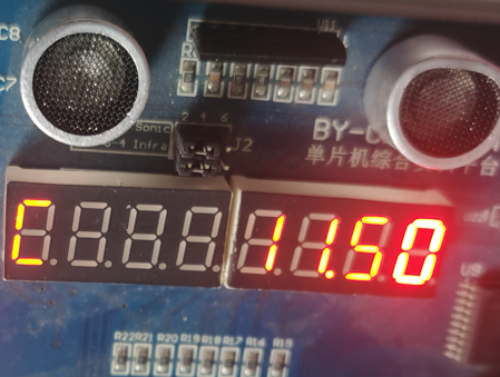
4, Attention to dynamic display of nixie tube
Sometimes you will find that the last nixie tube displayed will be brighter - that's because your last nixie tube is lit for the longest time.
Solution: artificially add one digit back to the number of nixie tubes used, so that the lighting time of each nixie tube before is the same. My code has written, interested can see.

5, The basic structure of the whole program

It is mainly divided into three folders:
The first one is used to store main C) documents;
The second CODE folder is used to store the basic CODE of the module, including the CODE of software delay. A delay is used separately C list the documents so that they can be cleared clearly;
The third USER folder is used to store the peripheral driver code used in this competition.
Peripheral code
This topic mainly uses two peripherals: AD/DA converter and temperature sensor.
PCF8591
IIC drive, corresponding IIC C and IIC H official documents are given. What we need to write is the function code: (DAC output)
Therefore, we should be very familiar with the process of IIC communication.
void DAC_Init(double dat)//The formal parameter is the value of the DAC that sets the output, ranging from 0 to 5V
{
    IIC_Start();
    IIC_SendByte(0x90);
    IIC_WaitAck();
    IIC_SendByte(0x40);
    IIC_WaitAck();
    IIC_SendByte((unsigned char)(dat * 255.0 / 5.0));
    IIC_WaitAck();
	IIC_Stop();
}
Here we explain the meaning of each:
0x90 is the address of PCF8591
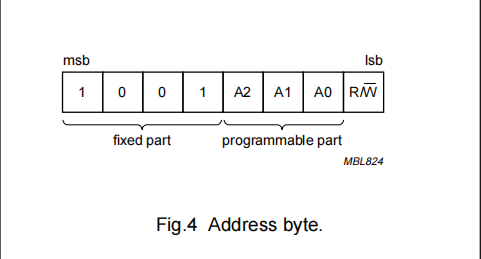
A2, A1 and A0 can be seen from the schematic diagram of the board that the connection is 0, and then here is write, so the last bit is also 0, so the whole address is 0x90.
0x40 is the function enabling code
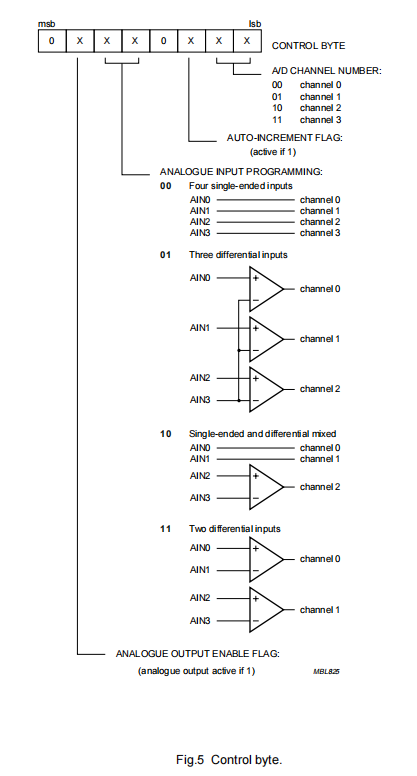
What we need is DAC output, so set bit 6 to 1 and the others to 0, so we get 0x40.
(unsigned char)(dat * 255.0 / 5.0)
PCF8591 is an 8-bit DAC, so the range is 0 ~ 255, averaging 0-5V. If I want to output any decimal between 0-5V, I can use this calculation method. Of course, the final type conversion is also required, because the format of IIC communication is unsigned char.
DS18B20
The underlying driver code of onewire bus protocol is officially given, but the official delay code has problems and needs to be manually modified:
void Delay_OneWire(unsigned char t)
{
    unsigned char i;
    while(t--)
    {
        for (i = 0; i < 12; i++);
    }
}
In this way, add the function code written by yourself:
unsigned int ds18bs20_read(void)
{
	unsigned int  low,high,temp;

	init_ds18b20();
	Write_DS18B20(0xCC);//Skip serial number
	Write_DS18B20(0x44);//Start temperature conversion
	init_ds18b20();//Initialize again
	Write_DS18B20(0xCC);//Skip serial number
	Write_DS18B20(0xBE);//Read temperature memory

	low=Read_DS18B20();//Lower 8 bits
	high=Read_DS18B20();//High 8 bits

	temp=high<<8;
	temp+=low;//Synthetic 16 bit data

	return temp;
}
The final converted temperature only needs to be multiplied by 0.0625. (my algorithm is only suitable for positive temperature. Why is it set to 0.0625? I suggest you look for information. I'm not very clear)
Programming ideas
First, pay attention to its power on initialization status - set the interface flag according to this, because the interface must be switched in the future. Then the initialization state is represented.
Then set the scanning of matrix keys in each interface to switch and convert functions.
Note: the DAC mode switching in this topic can be performed on any interface. Please pay attention to this.
Note: this topic displays the current interface state and mode state through different LED s. Therefore, a function should be designed to switch a light separately.
Here is my general idea:
void main(void)
{
    //Hardware initialization
    while(1)
    {
        if (Interface state == 1)
        {

        }
        else if (Interface state == 2)
        {

        }
        else if (Interface state == 3)
        {

        }

        switch(DAC pattern)
        {
            case 0:
                break;
            case 1:
                break;
        }
    }
}
It's not easy for bloggers to summarize. Praising three companies is the best affirmation.
If you need detailed code, you can download it from the following connection. If you want to consult, you can add me QQ2537900669.
It's not easy for bloggers to summarize. Praising three companies is the best affirmation.
If you need detailed code, you can download it from the following connection. If you want to consult, you can add me QQ2537900669.
The 12th Blue Bridge Cup MCU reference program - embedded document resources - CSDN Library