1, Foreword
In recent years, with the progress of science and technology and the arrival of intelligent wave, intelligent wearable devices are also developing rapidly. All kinds of health smart bracelets, smart watches, smart running shoes and smart glasses have been listed one after another, and there are many health management devices for individuals and families. All kinds of smart scales, such as fat scale, smart blood pressure meter, etc. are equipped with smart labels.
Wearable device, that is, a portable device worn directly on the body or integrated into the user's clothes or accessories. Wearable device is not only a hardware device, but also realizes powerful functions through software support, data interaction and cloud interaction. Wearable devices will bring great changes to life and perception.
This article uses STM32 and various peripheral sensors to cooperate with Huawei cloud IOT IOT platform to design a health management device, transmits data to Huawei cloud IOT platform through ESP8266+MQTT protocol, and completes application layer software development through the application side of Huawei cloud; The purpose of this project is to experience Huawei cloud Internet of things platform and explore the implementation principle of intelligent devices.
The currently designed monitoring and management equipment supports the following functions:
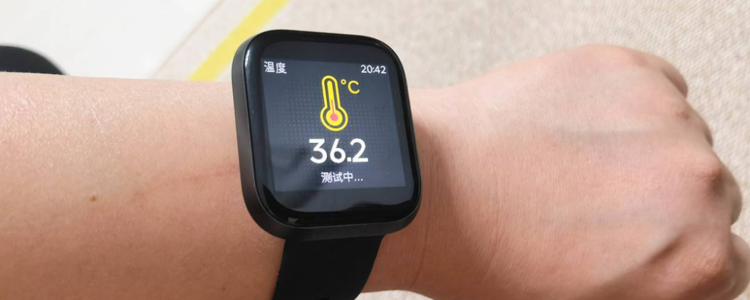
(1) Human body temperature measurement
(2) Motion monitoring and step counting function
(3) Sleep monitoring
(4) Heart rate measurement
STM32 collects these sensor data, processes them and completes the display on the local OLED display screen; Then the data is transferred to Huawei cloud Internet of things platform through ESP8266, and the data display is completed on the associated data visualization screen.
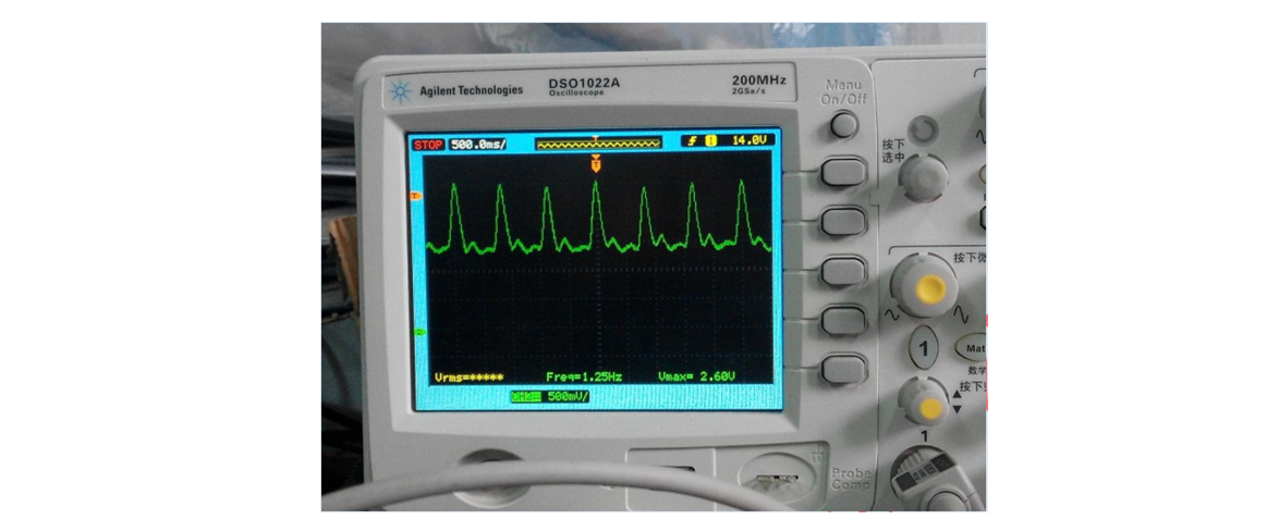
The following is the heart rate display measured by oscilloscope:
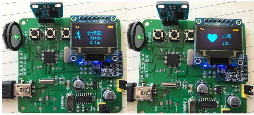
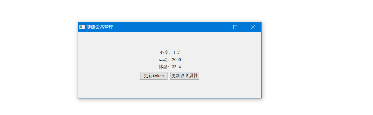
Equipment operation effect:
2, Hardware introduction
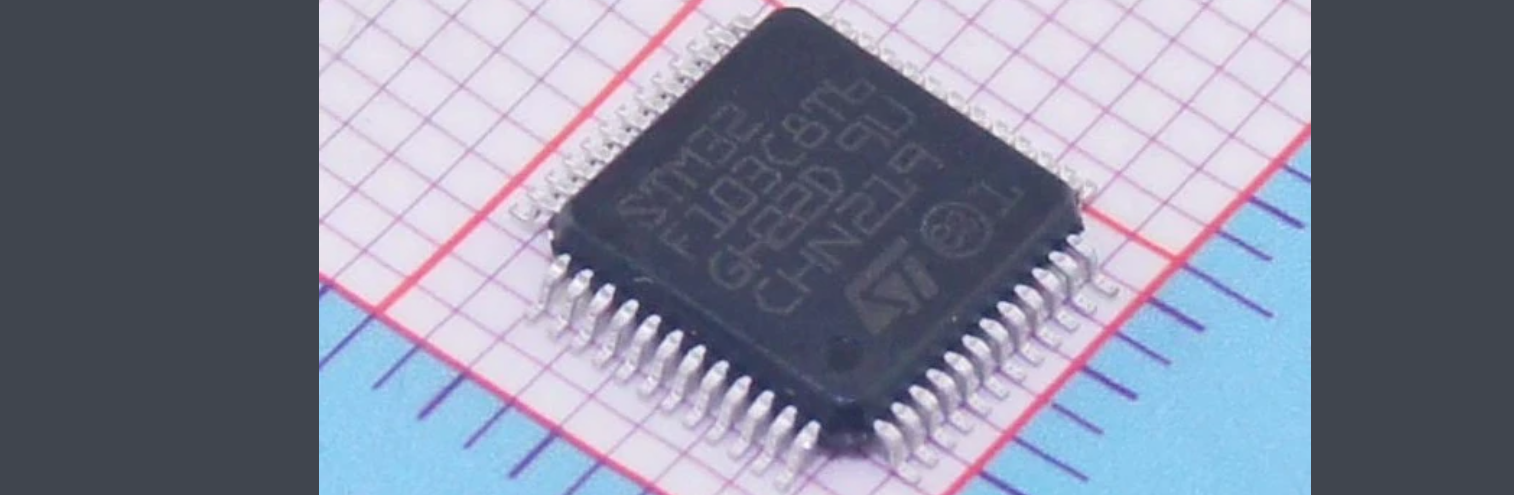
2.1 main control chip
The main control chip adopts STM32F103C8T6, which is a 32-bit microcontroller based on ARM Cortex-M core STM32 series. The program memory capacity is 64KB, RAM space is 20K, working voltage is 2V~3.6V and running speed is 72MHZ.
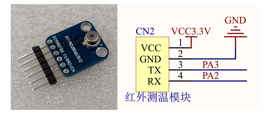
2.2 body temperature measurement
Human body temperature measurement adopts non-contact infrared temperature measurement chip gy-mcu 90615, with working voltage of 3-5v, small power consumption and small volume. Its working principle is to read infrared temperature data through single chip microcomputer and output it through serial port (TTL level) communication. The baud rate of serial port is 9600bps and 115200bps, and there are two modes of continuous output and inquiry output. It can adapt to different working environments and connect with all MCU and computers.
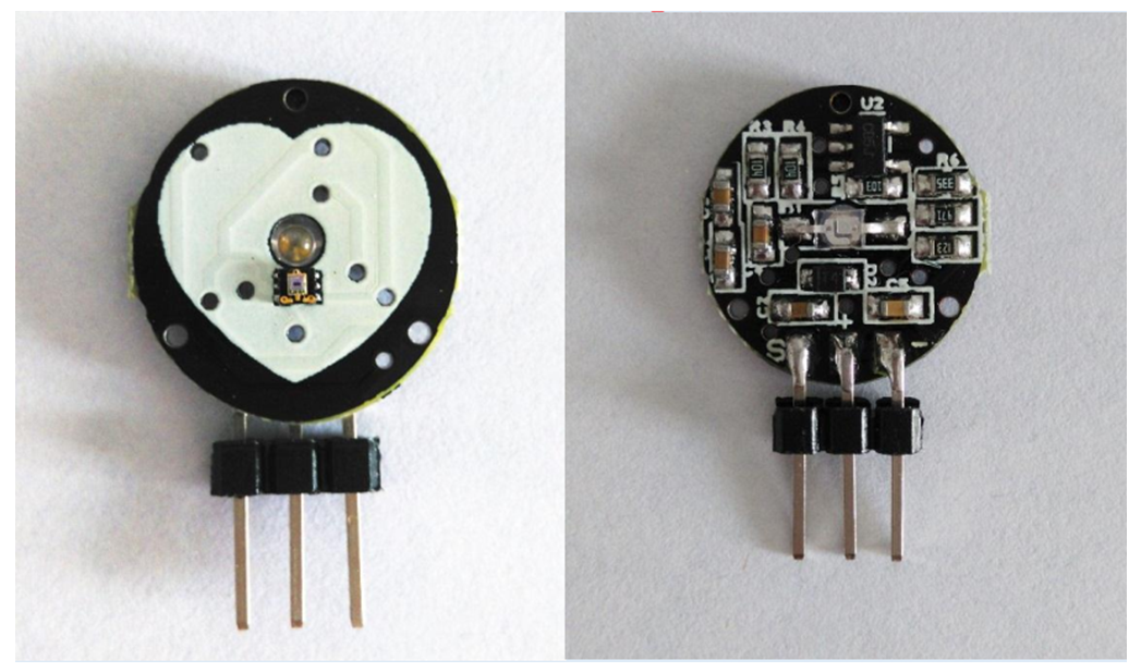
2.3 heart rate measurement
Pulse sensor is used for heart rate measurement, which is a photoelectric reflective analog sensor for pulse heart rate measurement. The collected analog signal can be transmitted to STM32 single chip microcomputer through the analog output port to convert it into digital signal, and then the heart rate value can be obtained after simple calculation by single chip microcomputer.
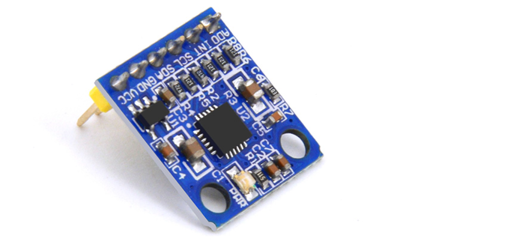
2.4 step counting and sleep monitoring functions
The step counting module, sleep monitoring and motion monitoring functions are realized by MUP6050 gyroscope, which is a six axis sensor of high-performance three-axis acceleration + three-axis gyroscope. The module adopts the MPU6050 chip of InvenSense company as the core. The chip integrates three-axis gyroscope and three-axis acceleration sensor, and can use its own digital motion processor hardware to accelerate the engine, Output the data after attitude calculation to the application terminal through the main IIC interface. With DMP, you can use the motion processing database provided by InvenSense company, which is very convenient to realize posture calculation, reduce the load of motion processing operation on the operating system, and greatly reduce the difficulty of development.
MPU6050 module has the characteristics of small volume, built-in DMP, built-in temperature sensor, supporting IIC slave address setting and interrupt, compatible with 3.3V/5V system, easy to use and so on.
(5) The OLED display for local data display adopts 0.96-inch SPI interface display with a resolution of 128 * 64, which mainly displays the collected data, time and other information locally.

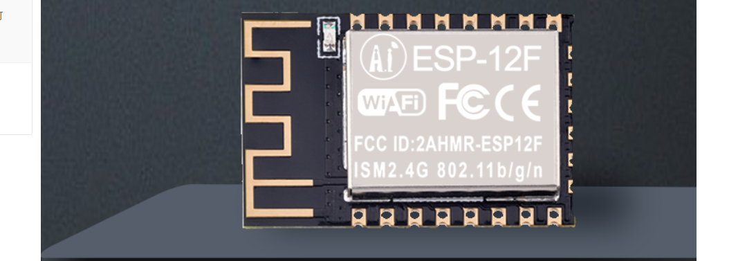
(6) The internet module adopts ESP8266, which is a common wireless network card chip in the field of Internet of things. It supports AT command and serial port protocol control. It only needs a few simple AT commands to complete network connection and data transmission. In the current project, the collected data is transferred to Huawei cloud IOT platform through ESP8266 to realize data display.
3, Creating IOT products and cloud testing
3.1 creating products
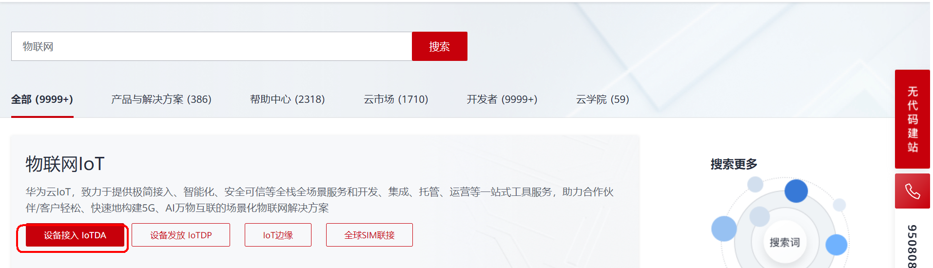
Official website address: https://www.huaweicloud.com/s/JeeJqeiBlOe9kSU
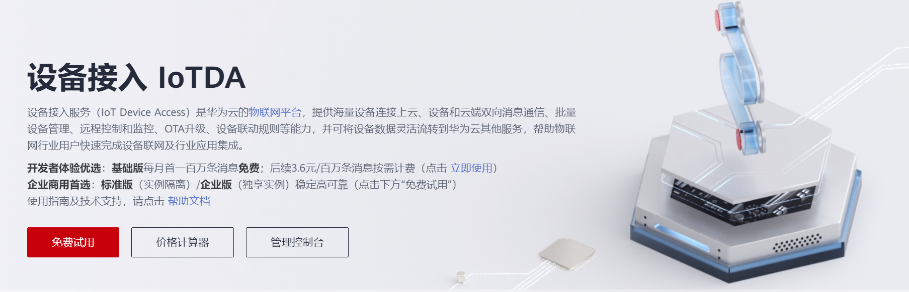
Choose IOTDA to enter and choose free trial.
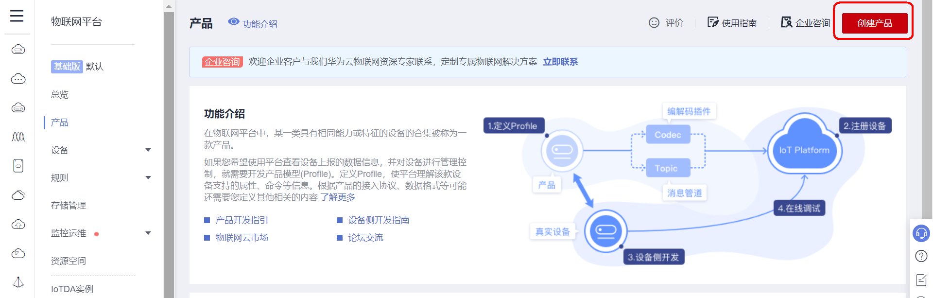
On the products page, select create product in the upper right corner.
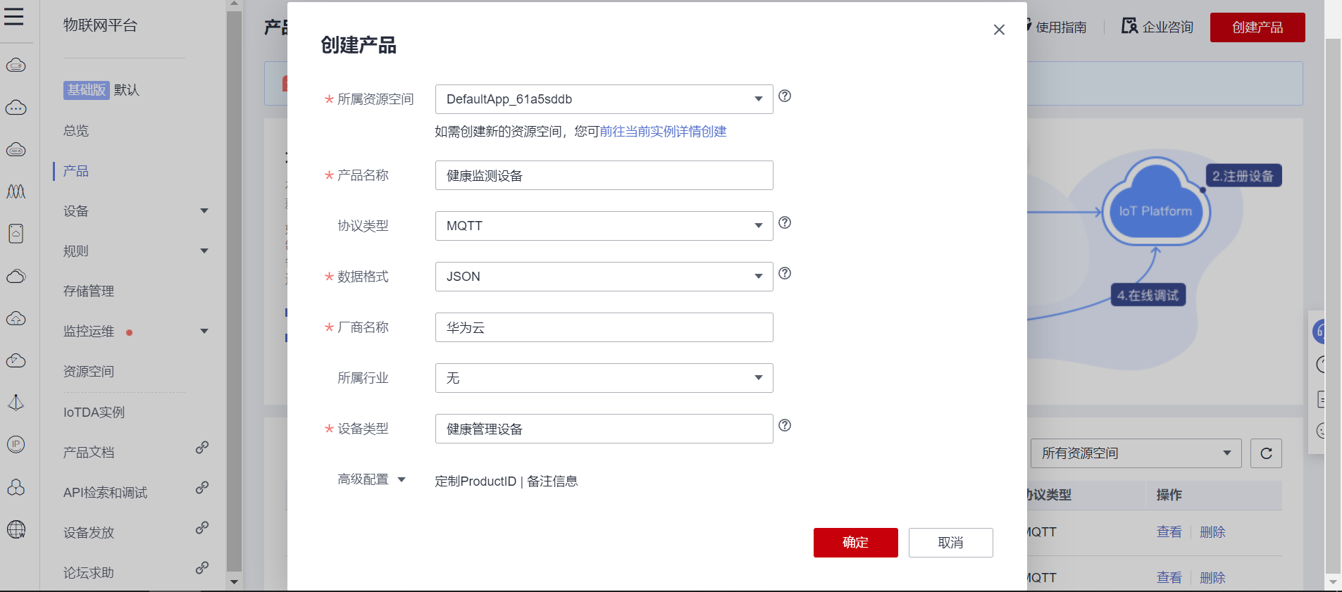
Fill in the corresponding parameters according to the prompts.
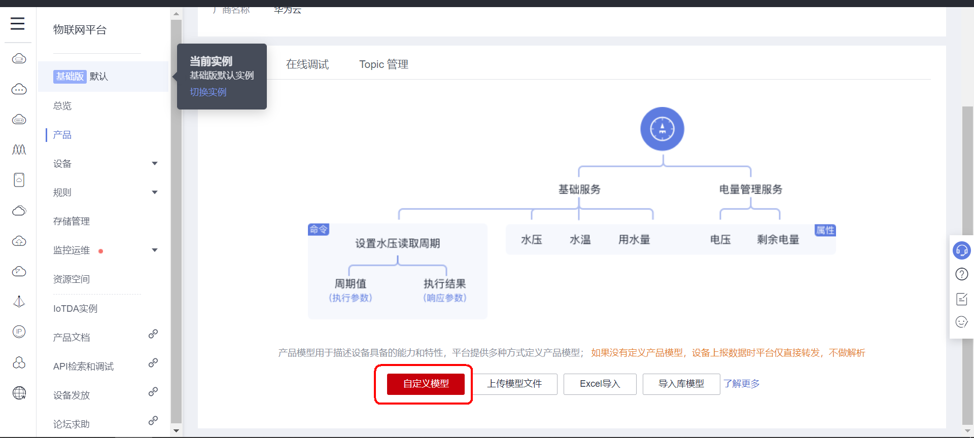
After creation, view the product details and enter the attribute configuration page.
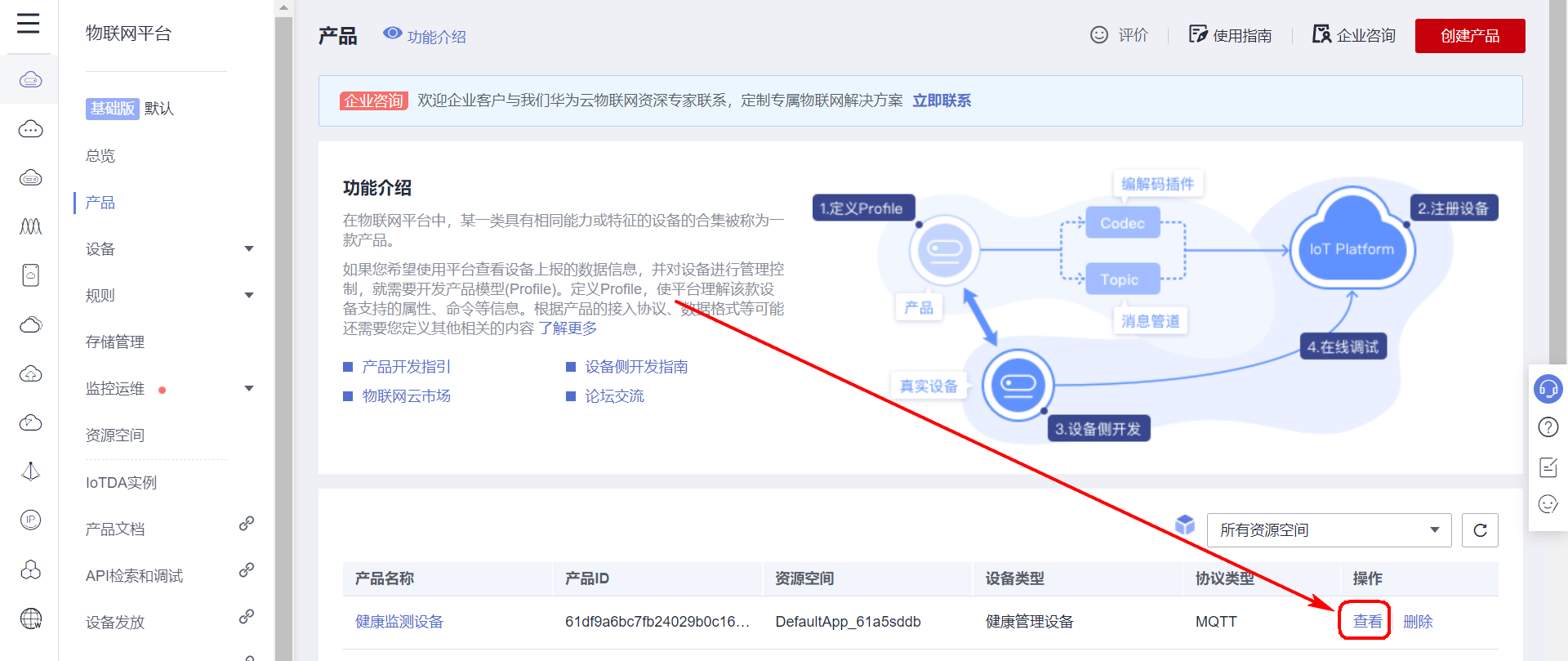
Select a custom model.
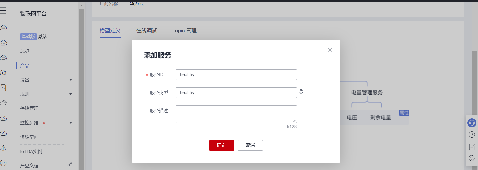
Add service.
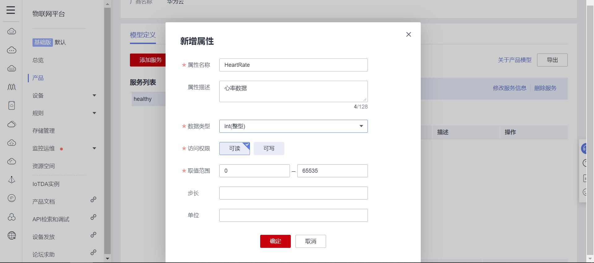
Next, add attributes, which are the data type uploaded by the sensor and the data to be displayed; It can be set according to the number and type of sensors.

Add heart rate sensor data attributes.
Add body temperature sensor data attributes.
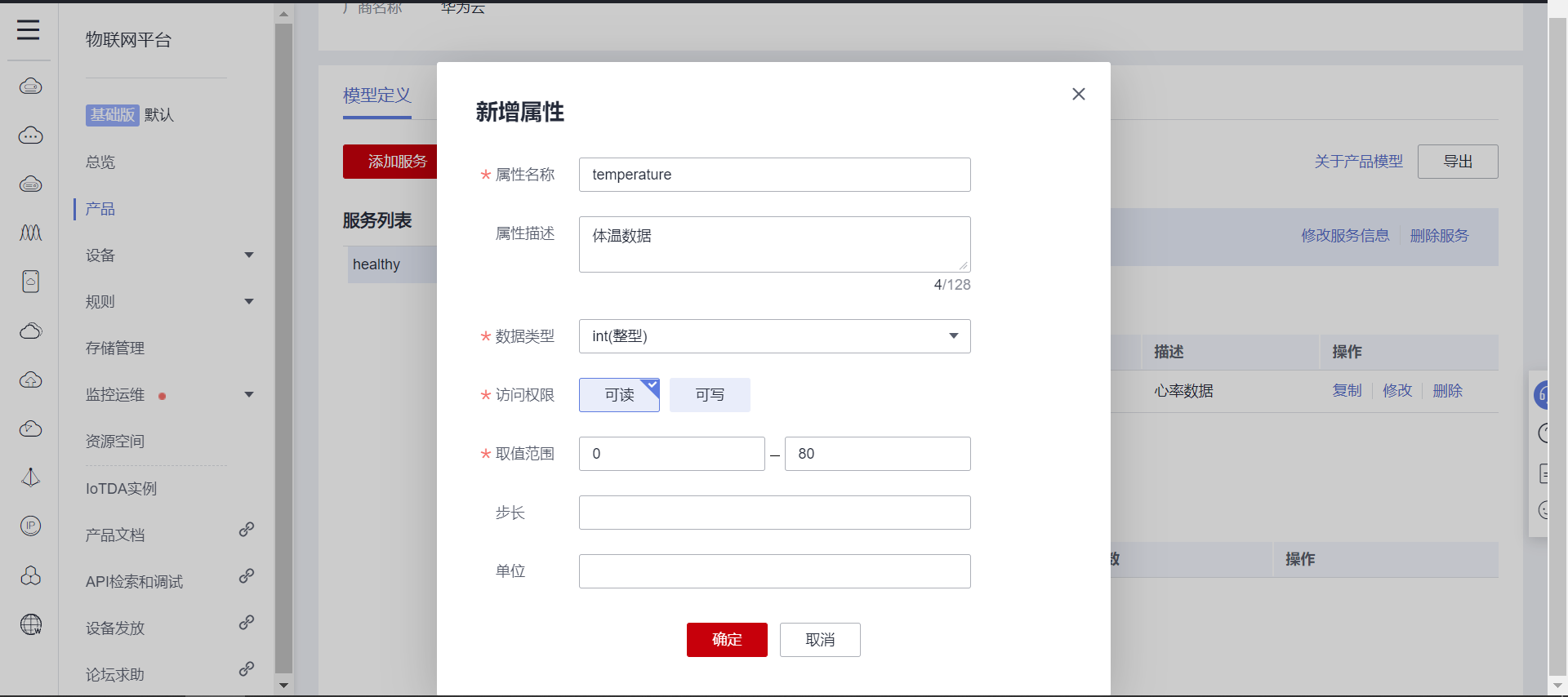
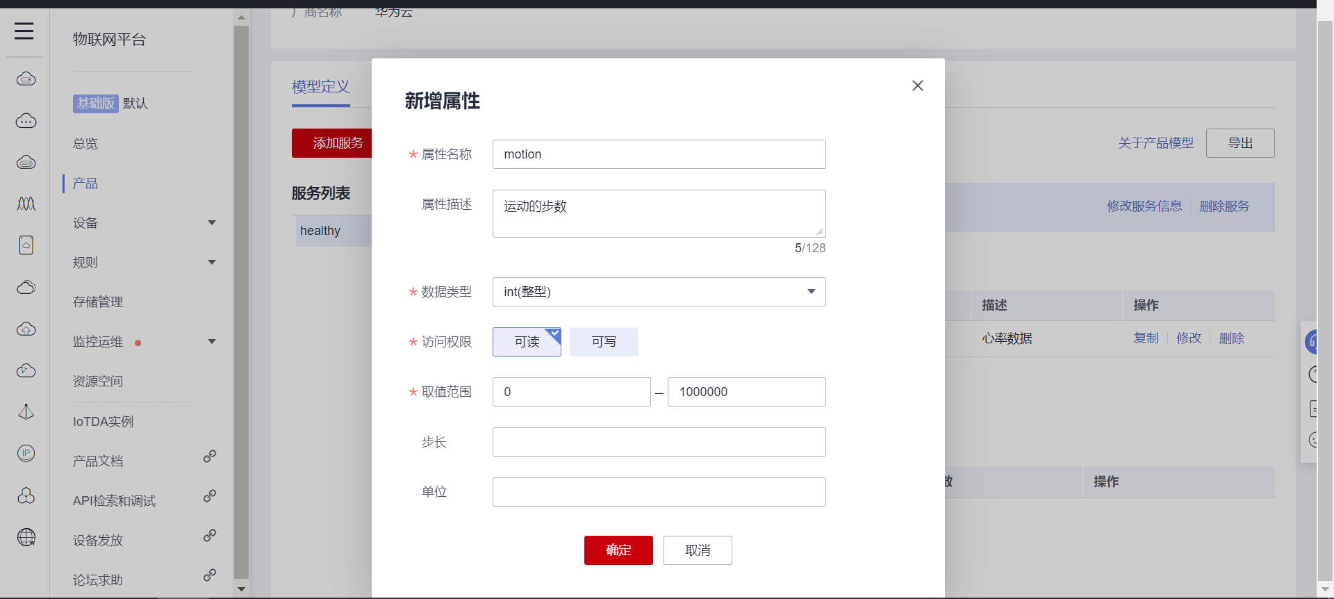
Add the data attribute of step counting function.
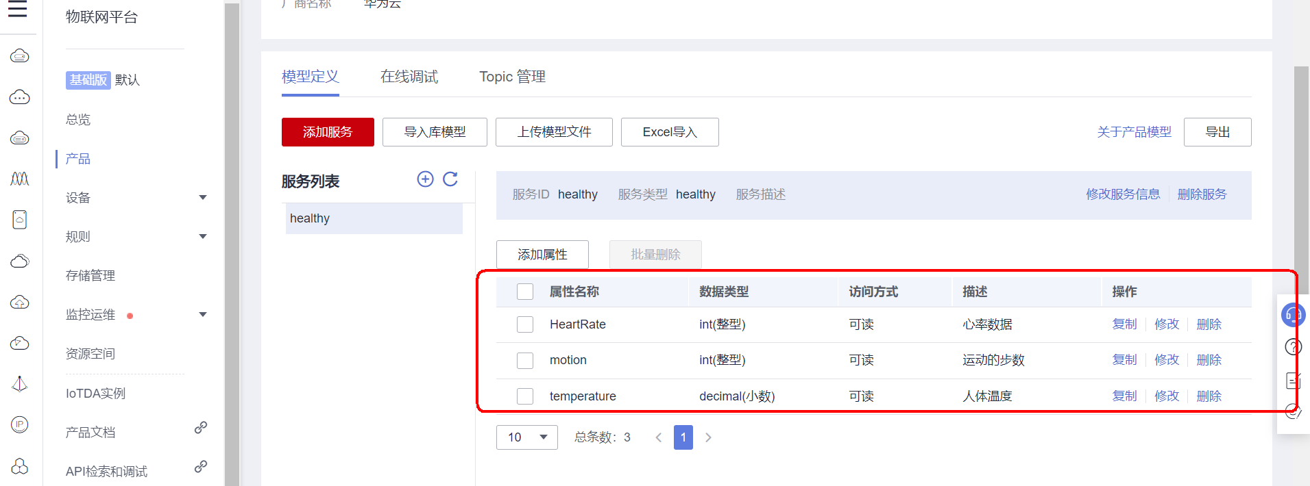
Created successfully:
3.2 registered equipment
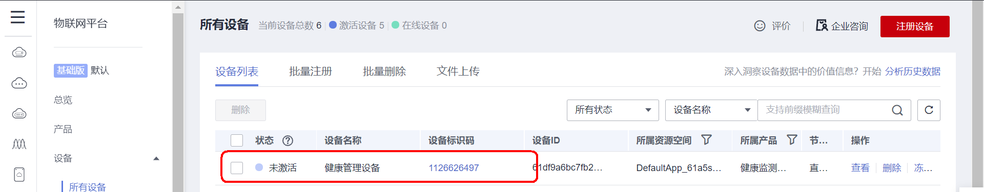
Open the equipment page, click the register equipment button in the upper right corner, and fill in according to the prompt and product information; After creating the saved information.
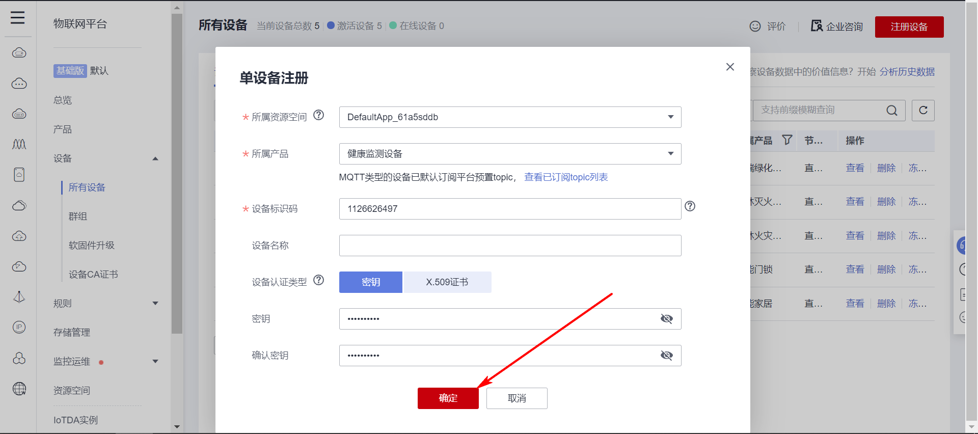
After clicking OK, the creation is successful, and the effect is as follows; At present, the device has not been activated yet. You need to log in to the server once to activate it; The next step is how to log in.
3.3 cloud test on equipment
After the creation of products and devices, the MQTT client is used to simulate the device to test whether it can be put into the cloud normally.
The connection protocol uses MQTT protocol. MQTT protocol logs in to the server. Just like QQ login, you need to enter account, password and other information; Let's use Huawei cloud gadgets to create these data.
MQTT account information generation online gadget provided by Huawei cloud: https://iot-tool.obs-website.cn-north-4.myhuaweicloud.com/
The data filled in the first two lines will be prompted when the device is created successfully. There are in the downloaded file. Just fill in according to it.
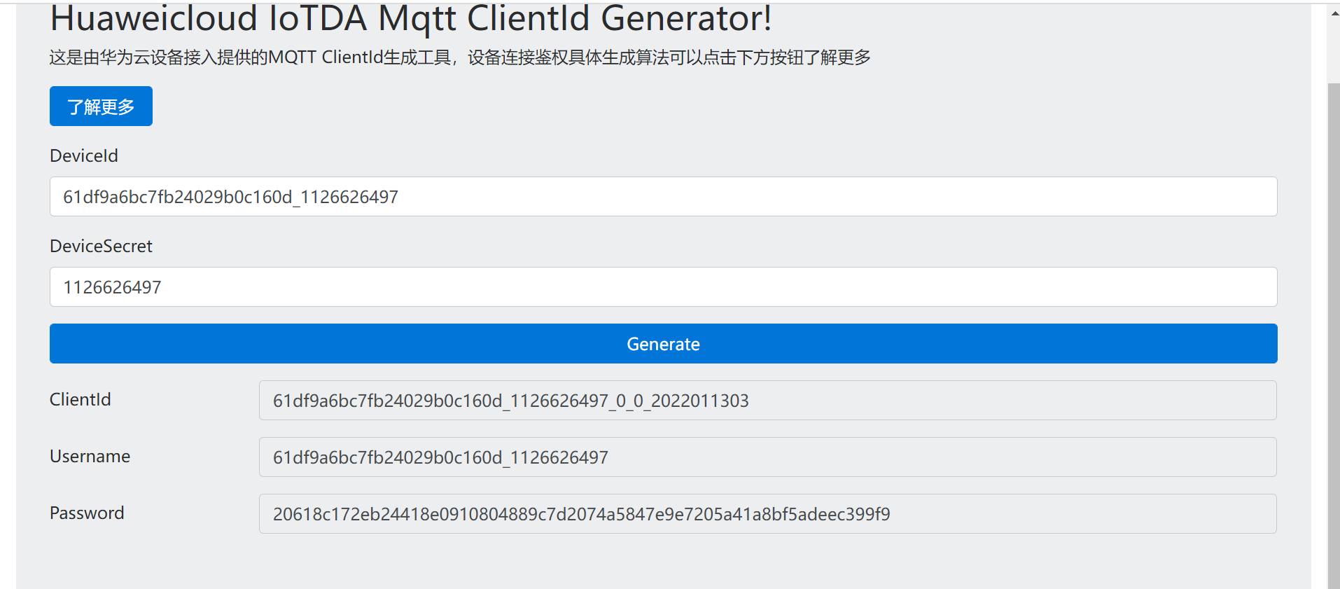
The data generated by my device is as follows:
ClientId   61df9a6bc7fb24029b0c160d_1126626497_0_0_2022011303
Username   61df9a6bc7fb24029b0c160d_1126626497
Password   20618c172eb24418e0910804889c7d2074a5847e9e7205a41a8bf5adeec399f9
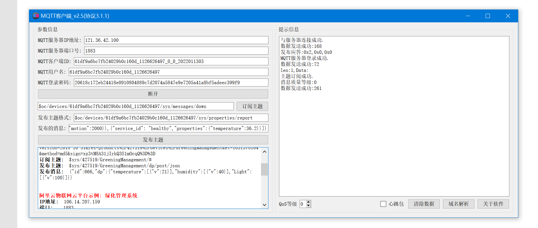
The MQTT server address information of Huawei cloud IOT platform is as follows:
port: 1883
 domain name: a161a58a78.iot-mqtts.cn-north-4.myhuaweicloud.com
IP address: 121.36.42.100
Format of MQTT protocol subscription topic of Huawei cloud IOT platform:
format: $oc/devices/{device_id}/sys/messages/down
//Subscription subject: the platform sends messages to devices
$oc/devices/61df9a6bc7fb24029b0c160d_1126626497/sys/messages/down
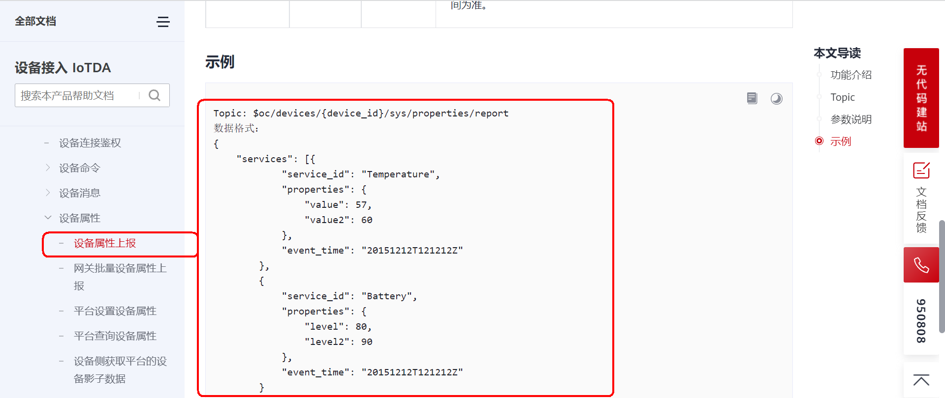
Format of MQTT protocol reporting subject of Huawei cloud IOT platform:
format: $oc/devices/{device_id}/sys/properties/report
//Device submission subject request
$oc/devices/61df9a6bc7fb24029b0c160d_1126626497/sys/properties/report


//The format of reported data is as follows:
{"services": [{"service_id": "healthy","properties":{"HeartRate":127}},{"service_id": "healthy","properties":{"motion":2000}},{"service_id": "healthy","properties":{"temperature":36.2}}]}
Open the MQTT client, fill in the corresponding data, and connect to Huawei cloud Internet of things platform:
If you need to use the same software as me, open Baidu search MQTT client_ v2. 4 (agreement 3.1.1) Exe to find the download address.
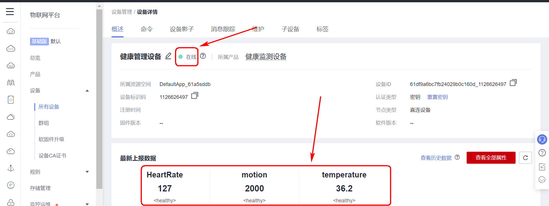
After successful login, check the Huawei cloud page to see that the device is online and the uploaded data has been displayed.
4, Application side software development
4.1 function introduction
In order to display the equipment data more conveniently and complete the interaction with the equipment, it is also necessary to develop a supporting upper computer. The official provides the API interface and SDK interface developed on the application side. In order to be more general, I use the API interface to complete the data interaction, and the upper computer software is developed by QT.
Help document address: https://support.huaweicloud.com/usermanual-iothub/iot_01_0045.html
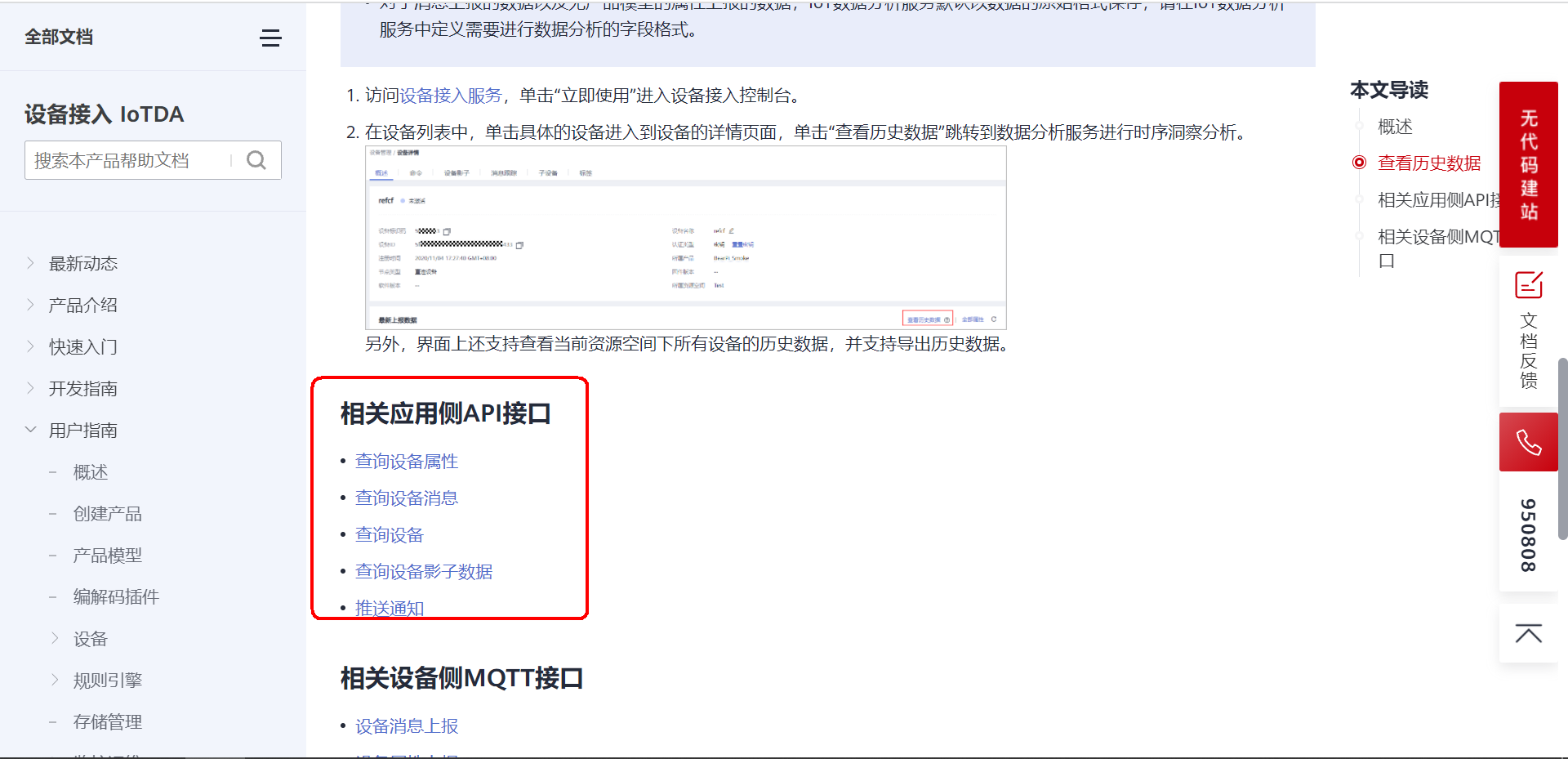
4.2 query device attribute interface
The device attribute is the sensor status data information uploaded by the device. The application side provides an API interface, which can actively send request instructions to the device end; After receiving the instruction, the device needs to report the data according to the agreed data format; Therefore, in order to realize the data interaction between the application layer and the device end, it needs the cooperation between the application layer and the device end.
The following describes the implementation process of application test and equipment test respectively.
(1) Instructions issued by the application layer
Help document address: https://support.huaweicloud.com/api-iothub/iot_06_v5_0034.html
Online debugging address of interface: https://apiexplorer.developer.huaweicloud.com/apiexplorer/debug?product=IoTDA&api=ListProperties
If the request parameters and return values are unclear, use the online debugging interface to experience before writing the code to verify whether the data interaction is OK.
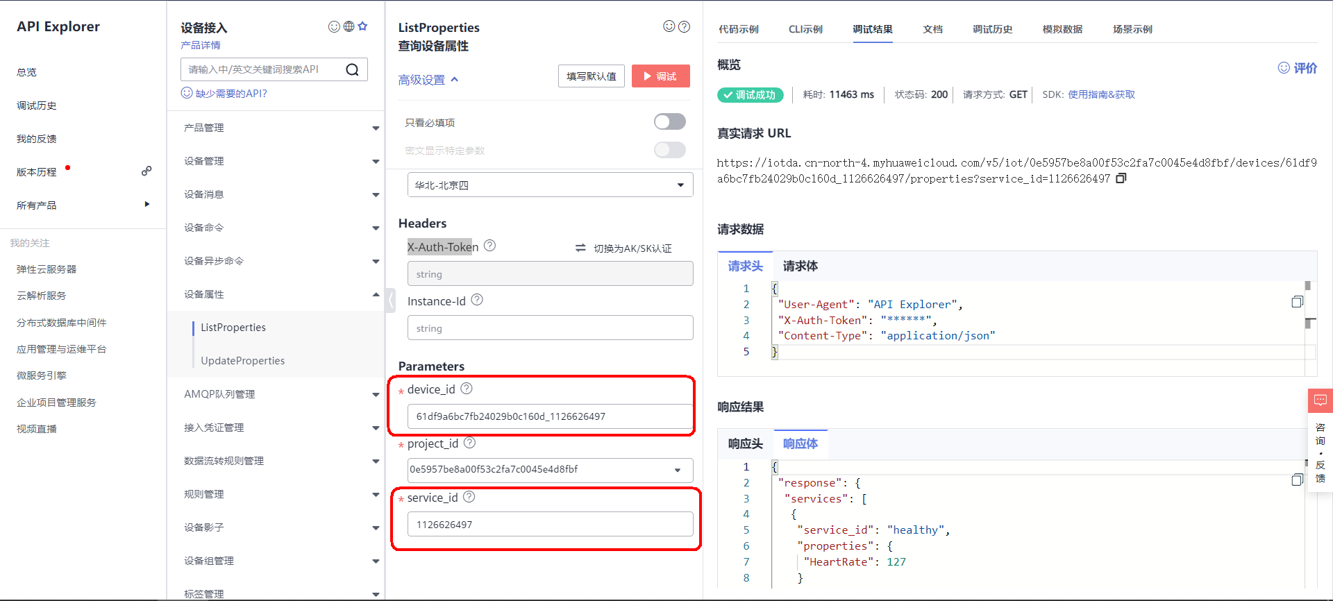
The two mandatory parameters in the request parameters are device ID and service ID. how to obtain these two parameters is described in Chapter 3. You can see the service ID when creating custom attributes on the product page.
Request interface summary:
Request method GET
URI address  /v5/iot/{project_id}/devices/{device_id}/properties
 transport protocol HTTPS

Spliced address:
https://iotda.cn-north-4.myhuaweicloud.com/v5/iot/0e5957be8a00f53c2fa7c0045e4d8fbf/devices/61df9a6bc7fb24029b0c160d_1126626497/properties?service_id=1126626497

Among them project_id and device_id It needs to be modified according to your own equipment information.


Header request:
{
 "User-Agent": "API Explorer",
 "X-Auth-Token": "******",   This is for authentication token
 "Content-Type": "application/json"
}


Responder(Data uploaded by the device)
{
 "response": {
  "services": [
   {
    "service_id": "healthy",
    "properties": {
     "HeartRate": 127
    }
   },
   {
    "service_id": "healthy",
    "properties": {
     "motion": 2000
    }
   },
   {
    "service_id": "healthy",
    "properties": {
     "temperature": 36.2
    }
   }
  ]
 }
}
The X-Subject-Token parameter needs to be filled in the request header. This parameter needs to be filled in as long as it is used to access any Huawei cloud. See here for the specific process. https://bbs.huaweicloud.com/blogs/317759 Turn to section 3.
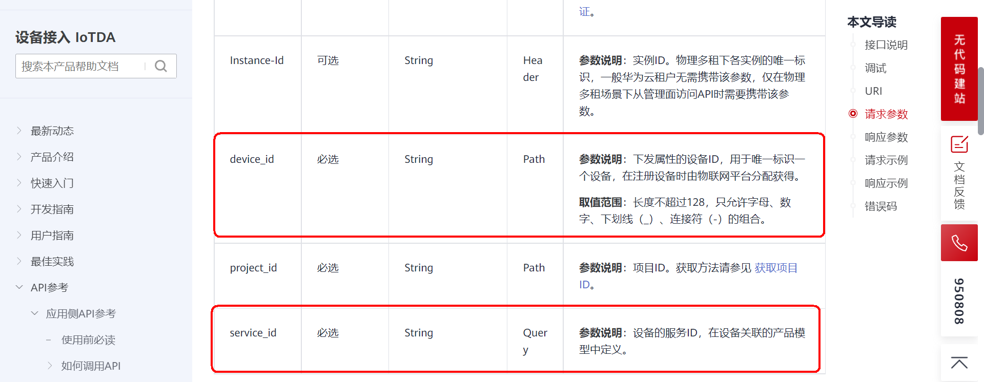
(2) Device upload data
When the application layer requests the device end to query the device attribute, the device end will receive the following message:
$oc/devices/61df9a6bc7fb24029b0c160d_1126626497/sys/properties/get/request_id=336bcb57-0e0a-44d0-90f7-31386cb54a3c{"service_id":"1126626497"}
There is a main parameter request in this message_ ID request ID, the device side needs to resolve this parameter. When responding to data to the application layer, it needs to bring this ID.
The detailed help document of this request attribute is shown here: https://support.huaweicloud.com/api-iothub/iot_06_v5_3011.html
Data format of device response:
Theme format: $oc/devices/{device_id}/sys/properties/get/response/request_id={request_id}

show    example:
$oc/devices/61df9a6bc7fb24029b0c160d_1126626497/sys/properties/get/response/request_id=336bcb57-0e0a-44d0-90f7-31386cb54a3c

Data format of response:
{"services": [{"service_id": "healthy","properties":{"HeartRate":127}},{"service_id": "healthy","properties":{"motion":2000}},{"service_id": "healthy","properties":{"temperature":36.2}}]}
The data format of the response can be described here: https://support.huaweicloud.com/api-iothub/iot_06_v5_3010.html
4.3 online API debugging combined with equipment simulation
Let's use MQTT client and online API interface to simulate the interface effect:
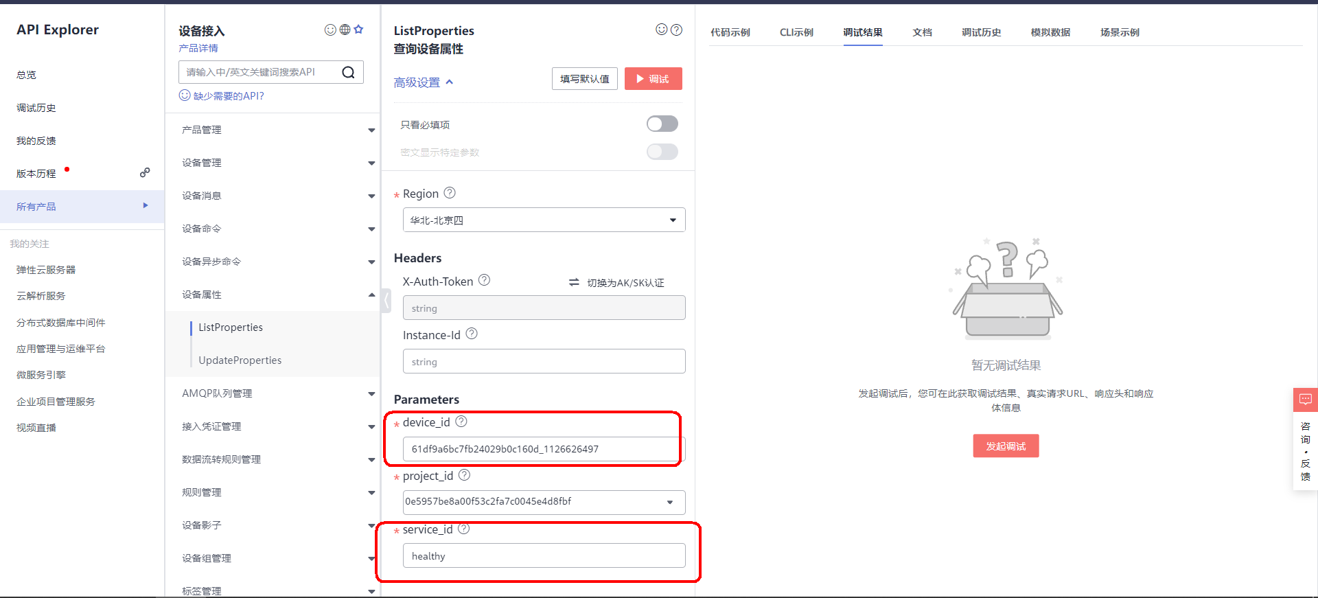
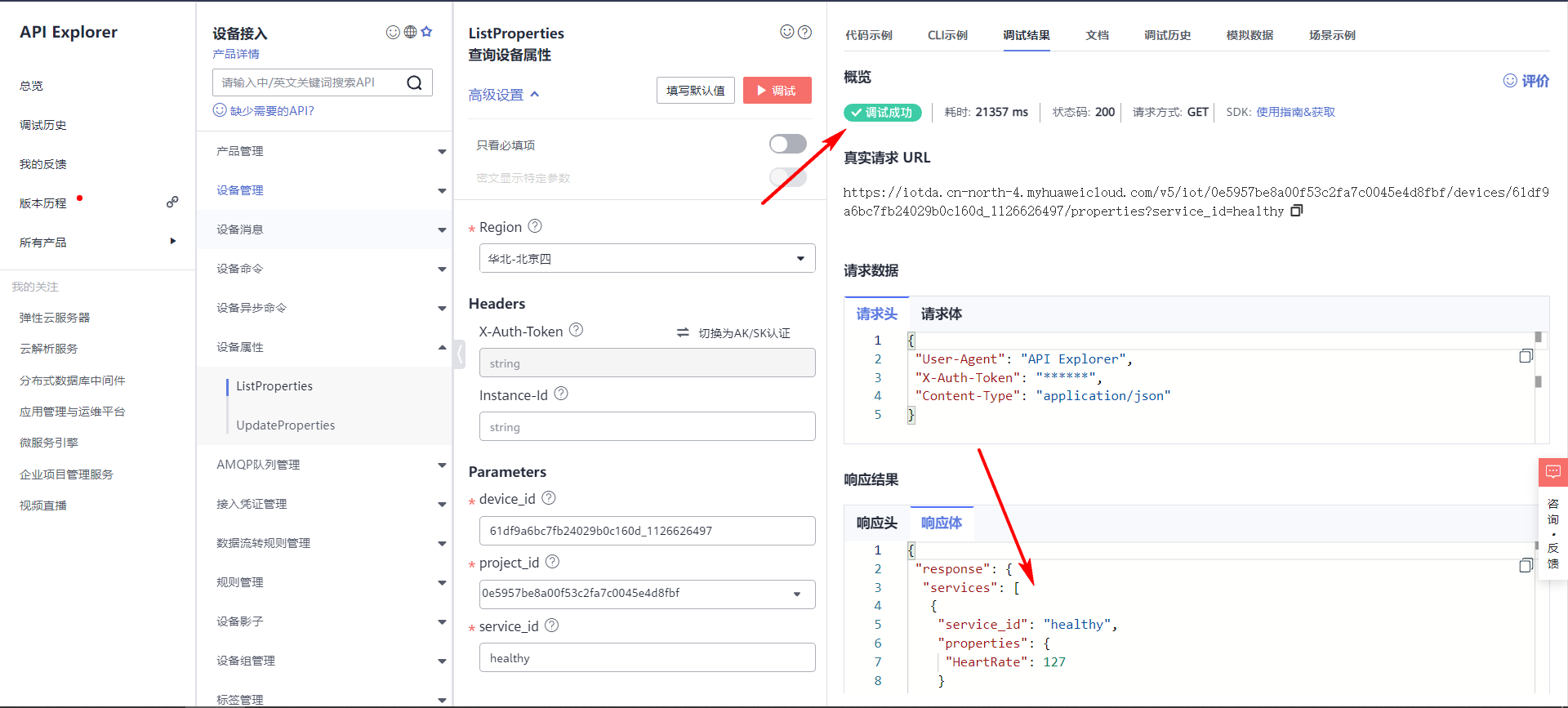
(1) Open the debugging page first: https://apiexplorer.developer.huaweicloud.com/apiexplorer/debug?product=IoTDA&api=ListProperties
Then fill in the equipment DI and service ID:
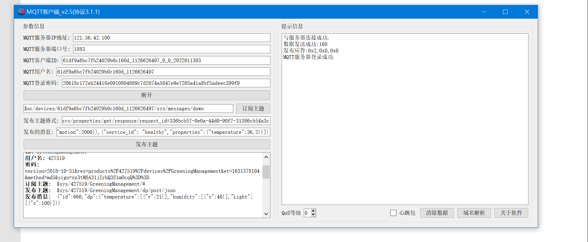
(2) Open the MQTT client and log in to Huawei cloud Internet of things platform (that is, the analog device goes online):
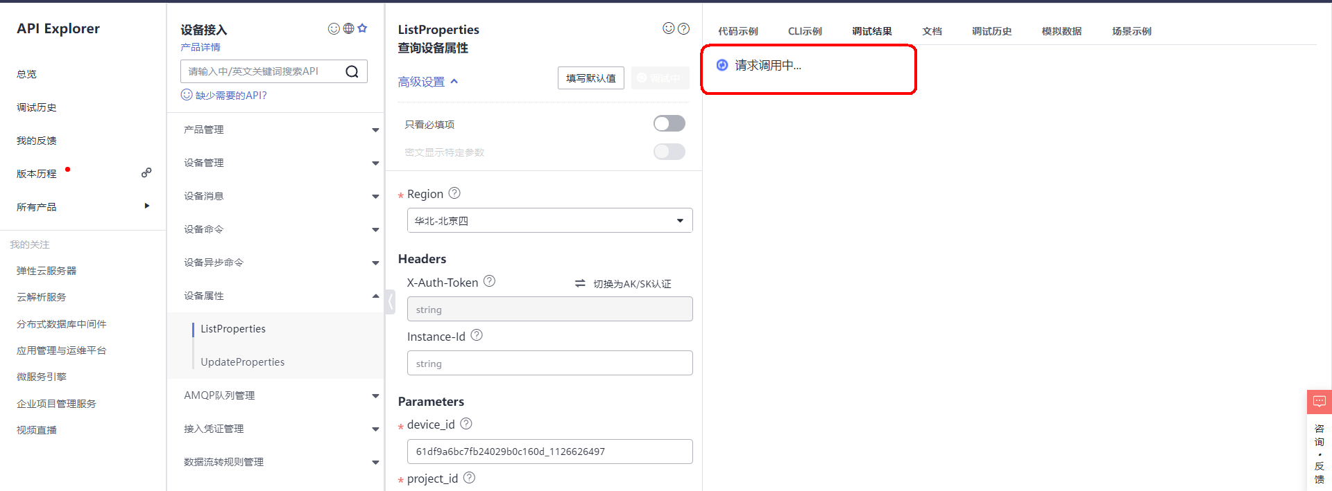
(3) Open the online API debugging page and click debug: after clicking, you can see that the page is waiting for the response of the client.
(4) . MQTT client response details
According to the response format mentioned above, splice the interface and data. Then publish the topic.
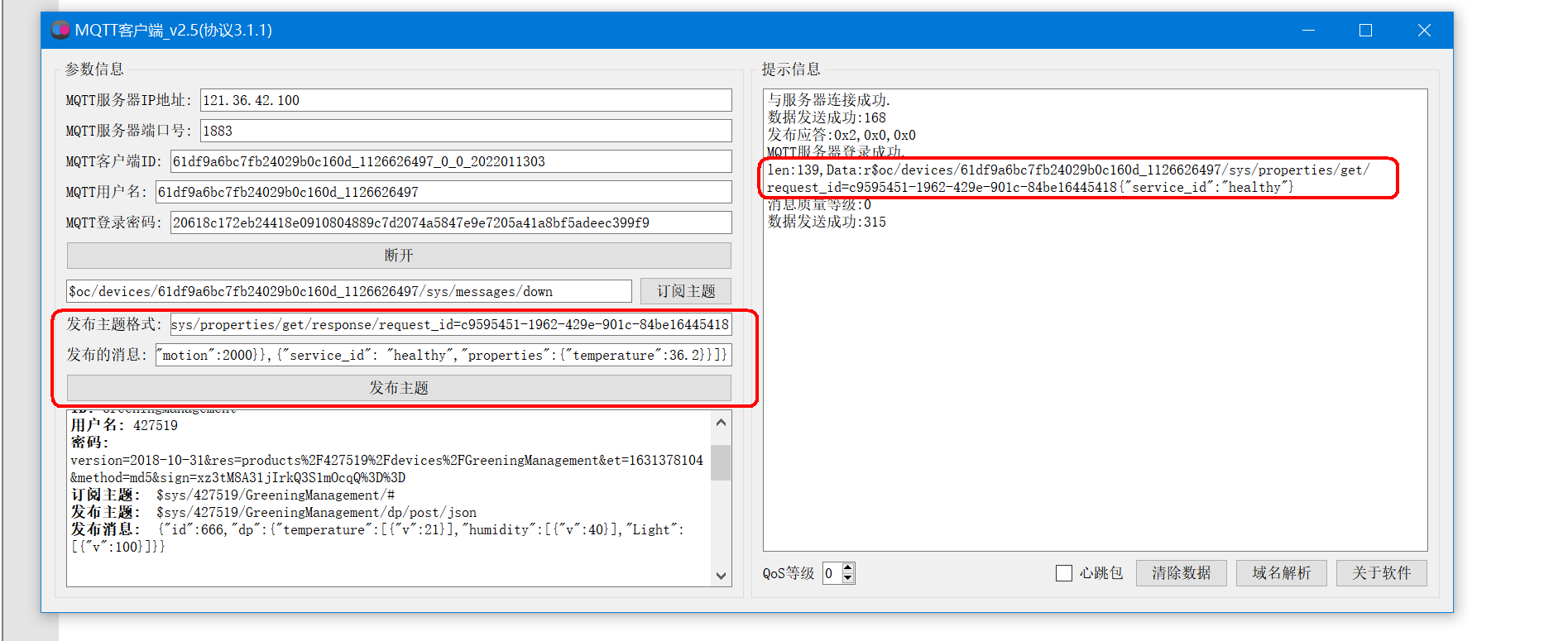
(5) . the application layer receives the response from the client and the debugging is successful
After successful debugging, the response body receives the device attribute data uploaded by the device end.
4.4 application layer core code
/*
Function: get token
*/
void Widget::GetToken()
{
    //Indicates to get the token
    function_select=3;

    QString requestUrl;
    QNetworkRequest request;

    //Set request address
    QUrl url;

    //Get token request address
    requestUrl = QString("https://iam.%1.myhuaweicloud.com/v3/auth/tokens")
                 .arg(SERVER_ID);

    //Create your own TCP server for testing
    //requestUrl="http://10.0.0.6:8080";

    //Format data submission
    request.setHeader(QNetworkRequest::ContentTypeHeader, QVariant("application/json;charset=UTF-8"));

    //Construction request
    url.setUrl(requestUrl);

    request.setUrl(url);

    QString text =QString("{\"auth\":{\"identity\":{\"methods\":[\"password\"],\"password\":"
    "{\"user\":{\"domain\": {"
    "\"name\":\"%1\"},\"name\": \"%2\",\"password\": \"%3\"}}},"
    "\"scope\":{\"project\":{\"name\":\"%4\"}}}}")
            .arg(MAIN_USER)
            .arg(IAM_USER)
            .arg(IAM_PASSWORD)
            .arg(SERVER_ID);

    //Send request
    manager->post(request, text.toUtf8());
}

//Query device properties
void Widget::Get_device_properties()
{
    //Indicates to get the token
    function_select=0;

    QString requestUrl;
    QNetworkRequest request;

    //Set request address
    QUrl url;

    //Get token request address
    requestUrl = QString("https://iotda.%1.myhuaweicloud.com/v5/iot/%2/devices/%3/properties?service_id=%4")
                 .arg(SERVER_ID)
            .arg(PROJECT_ID)
            .arg(device_id)
            .arg(service_id);

    //Create your own TCP server for testing
    //requestUrl="http://10.0.0.6:8080";

    //Format data submission
    request.setHeader(QNetworkRequest::ContentTypeHeader, QVariant("application/json"));

    //Set token
    request.setRawHeader("X-Auth-Token",Token);

    //Construction request
    url.setUrl(requestUrl);

    request.setUrl(url);

    //Send request
    manager->get(request);
}
5, Device bottom development
The following lists some sensor core processing codes at the bottom end of STM32 device.
5.1 heart rate acquisition and calculation algorithm
int BPM;                   			 // Used to save the pulse rate
int Signal;               			 // Raw data held
int IBI = 600;
unsigned char Pulse = false;
unsigned char QS = false;
int rate[10];
unsigned long sampleCounter = 0;
unsigned long lastBeatTime = 0;
int P =512;
int T = 512;
int thresh = 512;
int amp = 100;
unsigned char firstBeat = true;
unsigned char secondBeat = false;
/*
	Timer 2 interrupt service function is used to collect heart rate value periodically
*/
void TIM2_IRQHandler(void)
{
	uint16_t runningTotal=0;
	uint8_t i;
	uint16_t Num;

	if(TIM2->SR&1<<0)
	{
			//The read value shifts 2 bits to the right, 12 bits -- > 10 bits
		Signal = Get_AdcCHx_DATA(1)>>2;
		sampleCounter += 2;
		Num = sampleCounter - lastBeatTime;

		//The peaks and troughs of the pulse wave are found
		//  find the peak and trough of the pulse wave
		if(Signal < thresh && Num > (IBI/5)*3)
		{
			if (Signal < T)
			{
				T = Signal;
			}
		}

		if(Signal > thresh && Signal > P)
		{
			P = Signal;
		}

		//Start looking for heartbeat
		//When the pulse comes, the value of signal will rise
		if (Num > 250)
		{
			if ( (Signal > thresh) && (Pulse == false) && (Num > (IBI/5)*3) )
			{
				Pulse = true;
				//LED0(0);
				IBI = sampleCounter - lastBeatTime;
				lastBeatTime = sampleCounter;

				if(secondBeat)
				{
					secondBeat = false;
					for(i=0; i<=9; i++)
					{
						rate[i] = IBI;
					}
				}

				if(firstBeat)
				{
					firstBeat = false;
					secondBeat = true;
					return;
				}

				for(i=0; i<=8; i++)
				{
					rate[i] = rate[i+1];
					runningTotal += rate[i];
				}

				rate[9] = IBI;
				runningTotal += rate[9];
				runningTotal /= 10;
				BPM = 60000/runningTotal;
				QS = true;
			}
		}

		//Start descent pulse
		if (Signal < thresh && Pulse == true)
		{
			Pulse = false;
			amp = P - T;
			thresh = amp/2 + T;
			P = thresh;
			T = thresh;
		}

		//No pulse detected, set default value
		if (Num > 2500)
		{
			thresh = 512;
			P = 512;
			T = 512;
			lastBeatTime = sampleCounter;
			firstBeat = true;
			secondBeat = false;
		}
	}
	TIM2->SR&=0x0; //Clear interrupt flag
}
5.2 OLED key codes
//Write a byte to SSD1106.
//dat: data / command to write
//cmd: data / command flag 0, indicating command; 1. Represents data;
void OLED_WR_Byte(u8 dat,u8 cmd)
{
	u8 i;
	if(cmd)
	  OLED_DC_Set();
	else
	  OLED_DC_Clr();
	OLED_CS_Clr();
	for(i=0;i<8;i++)
	{
		OLED_SCLK_Clr();
		if(dat&0x80)
		   OLED_SDIN_Set();
		else
		   OLED_SDIN_Clr();
		OLED_SCLK_Set();
		dat<<=1;
	}
	OLED_CS_Set();
	OLED_DC_Set();
}

//Set the position of coordinates (x range: 0 ~ 127, y range: 0 ~ 63)
//Note: there are 64 lines in total, i.e. 8 pages
void OLED_Set_Pos(unsigned char x, unsigned char y)
{
	OLED_WR_Byte(0xb0+y,OLED_CMD);
	OLED_WR_Byte(((x&0xf0)>>4)|0x10,OLED_CMD);
	OLED_WR_Byte((x&0x0f)|0x01,OLED_CMD);
}
5.3 body temperature collection and conversion
u8 Receive_ok;
u8 rebuf[20]={0};
void RxTempInfo(void)
{
	 static uint8_t i=0;
	if(USART2->SR&1<<5)     //Judge reception flag
	{
		rebuf[i++]=USART2->DR;//Read the serial port data and clear the receiving flag at the same time
		if(rebuf[0]!=0x5a)    //Wrong frame header
			i=0;
		if((i==2)&&(rebuf[1]!=0x5a))//Wrong frame header
			i=0;

		if(i>3)//When i is equal to 4, the data volume byte rebuf[3] has been received
		{
			if(i!=(rebuf[3]+5))//Judge whether to receive a frame of data
				return ;
			switch(rebuf[2])   //Processing after receiving
			{
				case 0x45:
					if(!Receive_ok)//New data is received only after data processing is completed
					{
						 Receive_ok=1;//Reception completion flag
					}
					break;
				case 0x15:break;
				case 0x35:break;
			}
			i=0;//Cache clear 0
		}
	}
}

void GetTempInfo(void)
{
	float TO=0,TA=0;
    u8 sum=0,i=0;
	for(sum=0,i=0;i<(rebuf[3]+4);i++)
	{
	  	sum+=rebuf[i];
	}
	if(sum==rebuf[i])//Checksum judgment
	{
		TO=(float)((rebuf[4]<<8)|rebuf[5])/100;  //Get the real temperature
		TA=(float)((rebuf[6]<<8)|rebuf[7])/100;  //Get the real temperature
	}
	printf("TO: %f\r\n",TO);
	printf("TA: %f\r\n",TA);
}
5.4 motion step counting algorithm
/*******************************************************************************
* LOCAL VARIABLES
*/
//Store triaxial data
float oriValues[3] = {0};
//It is used to store the peak trough difference of the calculated threshold
float tempValue[VALUE_NUM] ={0};
int tempCount = 0;
//Rising flag bit
u8 isDirectionUp = FALSE;
//Continuous rise times
int continueUpCount = 0;
//The number of continuous rise of the previous point, in order to record the rise times of the wave crest
int continueUpFormerCount = 0;
//The state of the previous point, rising or falling
u8 lastStatus = FALSE;
//Wave peak
float peakOfWave = 0;
//Trough value
float valleyOfWave = 0;
//The time of this peak
long timeOfThisPeak = 0;
//Time of last peak
long timeOfLastPeak = 0;
//Current time
long timeOfNow = 0;
//Current sensor value
float gravityNew = 0;
//Last sensor value
float gravityOld = 0;
//Dynamic threshold requires dynamic data. This value is used for the threshold of these dynamic data
float initialValue = (float) 1.3;
//Initial threshold
float ThreadValue = (float) 2.0;
//Triaxial value
accValue_t accValue;
//Walking information: calories, mileage, steps
static sportsInfo_t sportsInfo;
//Step cache
static u8 stepTempCount =0;


/*******************************************************************************
* Function name: DetectorNewStep
* Function Description:
*		  Step update: if the wave crest is detected and meets the conditions of time difference and threshold, it is determined as step 1
*		  Threshold update: if the time difference condition is met and the difference between peak and trough is greater than initialValue, the difference will be included in the calculation of threshold
* Parameter Description:
Input:
values: Processed G-sensor data
timeStamp_p: time stamp
* Return value Description:
* Modify record: sportsInfo_t *onSensorChanged(accValue_t *pAccValue,timeStamp_t *timeStamp_p,personInfo_t * personInfo)
*******************************************************************************/
sportsInfo_t *DetectorNewStep(float values,timeStamp_t *timeStamp_p,personInfo_t * personInfo)
{
  static u32 time_old;
  personInfo_t *userInfo = personInfo;
  static u32 step_per_2_second;  //Steps taken every two seconds
  float step_lenth,walk_speed,walk_distance,Calories;//step
  u32 time_now;
  timeStamp_t *time_p = timeStamp_p;
  if (gravityOld == 0)
  {
    gravityOld = values;
  }
  else
  {
    if (DetectorPeak(values, gravityOld))//Wave crest detected
    {
      timeOfLastPeak = timeOfThisPeak;//Update time of last wave crest
      //Converts the timestamp to milliseconds
      time_now = timeOfNow = ((time_p->hour*60+time_p->minute)*60+time_p->second)*1000+time_p->twentyMsCount*20; //Gets the time and converts it to milliseconds
      //If the wave crest is detected and meets the conditions of time difference and threshold, it is determined as step 1
      if (  (timeOfNow - timeOfLastPeak >= 250 )//Jahol Fan is modified to 300 to prevent slight movement, and steps will also be detected
          //&& (timeOfNow - timeOfLastPeak <= 2000)
          &&(peakOfWave - valleyOfWave >= ThreadValue)
            )
      {
        timeOfThisPeak = timeOfNow; //Update the peak time


       	stepTempCount++;//Jahol: adding 1 is two steps
        step_per_2_second ++;
        //Jahol: the calculation of calories in this way can not filter out human misoperation. The result is that the mileage and calories are too large
        if((time_now - time_old) >= 2000 )    //If two seconds pass
        {

          if( 1 == step_per_2_second )
          {
            step_lenth = userInfo->height/5;
          }
          else if( 2 == step_per_2_second )
          {
            step_lenth = userInfo->height/4;
          }
          else if( 3 == step_per_2_second )
          {
            step_lenth = userInfo->height/3;
          }
          else if( 4 == step_per_2_second )
          {
            step_lenth = userInfo->height/2;
          }
          else if(5 == step_per_2_second)			  //Jahol: to make step counting accurate, set the upper limit to 5 steps at the expense of calorie accuracy
          {
            step_lenth = userInfo->height/1.2f;
          }
          else if( 7 == step_per_2_second )
          {
            step_lenth = userInfo->height;
          }
          else if(step_per_2_second >= 8)				//		step_diff>8
          {
            step_lenth = userInfo->height*1.2f;
          }
          else
          {
            step_lenth = 0;
          }
          walk_speed = step_per_2_second*step_lenth/2;   //Speed in meters per second
          walk_distance  = step_per_2_second*step_lenth; //Walking distance in meters
          Calories = 4.5f*walk_speed*(userInfo->weight/2)/1800;  //Jahol:weight is in kg
          sportsInfo.calories  += Calories;
          sportsInfo.distance  += walk_distance;
          time_old = time_now;         //Update time
          step_per_2_second = 0;

        }
        else
        {
          //do nothing
        }
        /*
        * Handle invalid motion:
        * 1.Step counting starts after 5 consecutive records
        * 2.For example, if the recorded step user stops for more than 3 seconds, the previous record will become invalid and start from the beginning next time
        * 3.The previous data is valid only after 4 consecutive steps are recorded and the user is still moving
        * */
        if ((stepTempCount< 5 )&&(timeOfNow - timeOfLastPeak >= 3000))
        {
          stepTempCount = 0;
        }
        else if((stepTempCount>= 5)&&(timeOfNow - timeOfLastPeak <= 3000))
        {
          sportsInfo.stepCount += stepTempCount;
          stepTempCount         = 0;
        }
        else
        {
          //do nothing
        }


      }
      //Jahol: update the threshold. Question: the threshold will not always become larger and smaller?
      if (timeOfNow - timeOfLastPeak >= 250
          && (peakOfWave - valleyOfWave >= initialValue))
      {
        timeOfThisPeak = timeOfNow;
        ThreadValue = Peak_Valley_Thread(peakOfWave - valleyOfWave);//Update Threshold
      }
    }
  }
  gravityOld = values;
  return &sportsInfo;
}