Networking requirements
When the network is relatively simple, or the router cannot establish a route to the destination network through the dynamic routing protocol, the static route can be configured. However, different from the dynamic routing protocol, the static routing itself has no detection mechanism. When the network fails, the static routing cannot be perceived and needs the intervention of the administrator. In this way, the link switching cannot be guaranteed in time, which may cause the interruption of the service for a long time.
The scheme of deploying BFD for static routing can adapt to the changes of the link, but BFD for static routing requires that the devices at both ends of the link support BFD function. If there are devices at both ends of the link that do not support BFD function, NQA for IPv4 static routing can be configured. After NQA test case detects link failure, it will delete the static routing bound to it from the IP routing table, so as to switch the service flow to the route without link failure and avoid long-term service interruption.
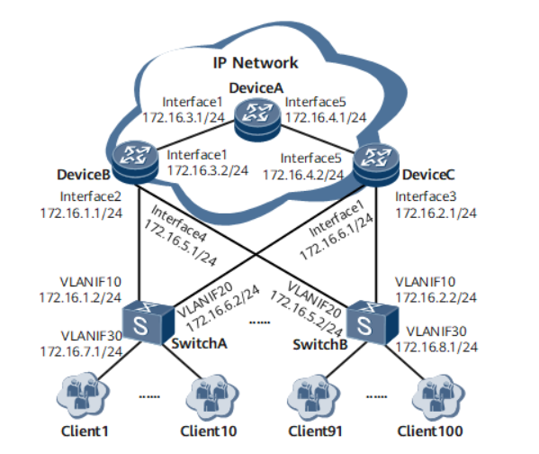
As shown in Figure 1, in the IP MAN networking, the network is designed as a redundant backup link, in which:
- Configure static routes to users on both DeviceB and DeviceC. DeviceB is the main device and DeviceC is the standby device;
- Under normal conditions, the service flow is required to go through the main link DeviceB → SwitchA;
- When the primary link fails, the service flow is switched to the standby link DeviceC → SwitchA.
Figure 1 # NQA for IPv4 static routing networking diagram
Configuration ideas
- Create an ICMP type NQA test case to detect the failure of the primary link. Establish an ICMP type NQA test case between the NQA test case client DeviceB and the tested device SwitchA to detect whether the main link DeviceB → SwitchA is normal.
- Configure static routing and bind NQA test cases on the primary link. Configure the static route on DeviceB and DeviceC, and configure the static route on DeviceB to link with NQA. When the NQA test case detects a link failure, notify the route management module to delete the static route from the IP route table.
- Configure dynamic routing protocol. Configure dynamic routing protocols on DeviceA, DeviceB and DeviceC so that these devices can learn routing from each other.
- OSPF protocol introduces static routing and sets a lower overhead value for the main link. Configure OSPF protocol on DeviceB and DeviceC to introduce static routing, and set a high overhead value for the static routing introduced by DeviceC. When DeviceA learns the route to the same destination address from DeviceB and DeviceC, it will give priority to the link DeviceB → SwitchA with low overhead value.
Operation steps
1. Configure the IP address. Please refer to the configuration file for the specific configuration process
2. Configure NQA test cases between DeviceB and SwitchA on DeviceB
<DeviceB> system-view
[~DeviceB] nqa test-instance user test
[*DeviceB-nqa-user-test] test-type icmp
[*DeviceB-nqa-user-test] destination-address ipv4 172.16.1.2
[*DeviceB-nqa-user-test] frequency 10
[*DeviceB-nqa-user-test] probe-count 2
[*DeviceB-nqa-user-test] interval seconds 5
[*DeviceB-nqa-user-test] timeout 4
[*DeviceB-nqa-user-test] start now
[*DeviceB-nqa-user-test] commit
[~DeviceB-nqa-user-test] quit
3. Configure static routing
#Test the linkage between NQA and DeviceB.
[~DeviceB] ip route-static 172.16.7.0 255.255.255.0 GigabitEthernet 1/0/1 172.16.1.2 track nqa user test
[*DeviceB] commit
#Configure static routing on DeviceC.
[*DeviceC] ip route-static 172.16.7.0 255.255.255.0 GigabitEthernet 1/0/0 172.16.6.2
[*DeviceC] commit
4. Configure dynamic routing protocol on DeviceA, DeviceB and DeviceC. This example selects OSPF dynamic routing protocol.
#Configure OSPF protocol on DeviceA.
[~DeviceA] ospf 1
[*DeviceA-ospf-1] area 0.0.0.0
[*DeviceA-ospf-1-area-0.0.0.0] network 172.16.3.0 0.0.0.255
[*DeviceA-ospf-1-area-0.0.0.0] network 172.16.4.0 0.0.0.255
[*DeviceA-ospf-1-area-0.0.0.0] quit
[*DeviceA-ospf-1] quit
[*DeviceA] commit
#Configure OSPF protocol on DeviceB.
[~DeviceB] ospf 1
[*DeviceB-ospf-1] area 0.0.0.0
[*DeviceB-ospf-1-area-0.0.0.0] network 172.16.3.0 0.0.0.255
[*DeviceB-ospf-1-area-0.0.0.0] quit
[*DeviceB-ospf-1] quit
[*DeviceB] commit
#Configure OSPF protocol on DeviceC.
[~DeviceC] ospf 1
[*DeviceC-ospf-1] area 0.0.0.0
[*DeviceC-ospf-1-area-0.0.0.0] network 172.16.4.0 0.0.0.255
[*DeviceC-ospf-1-area-0.0.0.0] quit
[*DeviceC-ospf-1] quit
[*DeviceC] commit
5. Configure OSPF dynamic routing protocol on DeviceB and DeviceC to introduce static routing
#Configure OSPF dynamic routing protocol on DeviceB, introduce static routing, and set the routing overhead value to 10.
[~DeviceB] ospf 1
[*DeviceB-ospf-1] import-route static cost 10
[*DeviceB-ospf-1] commit
[~DeviceB-ospf-1] quit
#Configure OSPF dynamic routing protocol on DeviceC, introduce static routing, and set the routing overhead value to 20.
[*DeviceC] ospf 1
[*DeviceC-ospf-1] import-route static cost 20
[*DeviceC-ospf-1] commit
[~DeviceC-ospf-1] quit
6. View configuration results
After the configuration is completed, execute the display current configuration | include NQA command on DeviceB in the system view. You can see that the NQA test case has been bound to the static route. Execute the display nqa results command to see that the NQA test case has been established.
#View the NQA for static routing configuration.
[~DeviceB] display current-configuration | include nqa
 ip route-static 172.16.7.0 255.255.255.0 GigabitEthernet 1/0/1 172.16.1.2 track nqa user test
 nqa test-instance user test
#View NQA test results.
[~DeviceB] display nqa results test-instance user test
 NQA entry(user, test) : testflag is active ,testtype is icmp
  1 . Test 6645 result   The test is finished
   Send operation times: 2                Receive response times: 2
   Completion:success                   RTD OverThresholds number:0
   Attempts number:1                      Drop operation number:0
   Disconnect operation number:0          Operation timeout number:0
   System busy operation number:0         Connection fail number:0
   Operation sequence errors number:0     RTT Stats errors number:0
   Destination ip address:172.16.1.2
   Min/Max/Average Completion Time: 1/1/1
   Sum/Square-Sum  Completion Time: 2/2
   Last Good Probe Time: 2012-11-14 04:20:36.9
   Lost packet ratio: 0 %
You can see "Lost packet ratio: 0%", which indicates that the link is in good condition.
#Check the route table of DeviceB, and you can see that the static route exists in the route table.
[~DeviceB] display ip routing-table
Route Flags: R - relay, D - download to fib, T - to vpn-instance, B - black hole route
------------------------------------------------------------------------------
Routing Table : _public_
         Destinations : 15       Routes : 15

Destination/Mask    Proto   Pre  Cost        Flags NextHop         Interface

      127.0.0.0/8   Direct  0    0             D  127.0.0.1       InLoopBack0
      127.0.0.1/32  Direct  0    0             D  127.0.0.1       InLoopBack0
127.255.255.255/32  Direct  0    0             D  127.0.0.1       InLoopBack0
     172.16.1.0/24  Direct  0    0             D  172.16.1.1      GigabitEthernet1/0/1
     172.16.1.1/32  Direct  0    0             D  127.0.0.1       GigabitEthernet1/0/1
   172.16.1.255/32  Direct  0    0             D  127.0.0.1       GigabitEthernet1/0/1
     172.16.3.0/24  Direct  0    0             D  172.16.3.2      GigabitEthernet1/0/0
     172.16.3.2/32  Direct  0    0             D  127.0.0.1       GigabitEthernet1/0/0
   172.16.3.255/32  Direct  0    0             D  127.0.0.1       GigabitEthernet1/0/0
     172.16.4.0/24  OSPF    10   2             D  172.16.3.1      GigabitEthernet1/0/0
     172.16.5.0/24  Direct  0    0             D  172.16.5.1      GigabitEthernet1/0/3
     172.16.5.1/32  Direct  0    0             D  127.0.0.1       GigabitEthernet1/0/3
   172.16.5.255/32  Direct  0    0             D  127.0.0.1       GigabitEthernet1/0/3
   172.16.7.0/24  Static  60   0             D  172.16.1.2      GigabitEthernet1/0/1
255.255.255.255/32  Direct  0    0             D  127.0.0.1       InLoopBack0
#View the routing table of DeviceA.
[~DeviceA] display ip routing-table
Route Flags: R - relay, D - download to fib, T - to vpn-instance, B - black hole route
------------------------------------------------------------------------------
Routing Table : _public_
         Destinations : 11       Routes : 11

Destination/Mask    Proto   Pre  Cost        Flags NextHop         Interface

      127.0.0.0/8   Direct  0    0             D  127.0.0.1       InLoopBack0
      127.0.0.1/32  Direct  0    0             D  127.0.0.1       InLoopBack0
127.255.255.255/32  Direct  0    0             D  127.0.0.1       InLoopBack0
     172.16.3.0/24  Direct  0    0             D  172.16.3.1      GigabitEthernet1/0/0
     172.16.3.1/32  Direct  0    0             D  127.0.0.1       GigabitEthernet1/0/0
   172.16.3.255/32  Direct  0    0             D  127.0.0.1       GigabitEthernet1/0/0
     172.16.4.0/24  Direct  0    0             D  172.16.4.1      GigabitEthernet2/0/3
     172.16.4.1/32  Direct  0    0             D  127.0.0.1       GigabitEthernet2/0/3
   172.16.4.255/32  Direct  0    0             D  127.0.0.1       GigabitEthernet2/0/3
     172.16.7.0/24  O_ASE   150  10            D  172.16.3.2     GigabitEthernet1/0/0
255.255.255.255/32  Direct  0    0             D  127.0.0.1       InLoopBack0
It can be seen that there is a route to 172.16.7.0/24. The next hop points to 172.16.3.2, and the cost value is 10. Therefore, the service traffic will take the link DeviceB → SwitchA first.
#Close the GigabitEthernet 1/0/1 interface of DeviceB to simulate link failure.
[~DeviceB] interface GigabitEthernet 1/0/1
[~DeviceB-GigabitEthernet1/0/1] shutdown
[~DeviceB-GigabitEthernet1/0/1] commit
[~DeviceB] quit
#View NQA test results.
[~DeviceB] display nqa results test-instance user test
 NQA entry(user, test) : testflag is active ,testtype is icmp
  1 . Test 7160 result   The test is finished
   Send operation times: 2                Receive response times: 0
   Completion:failed                    RTD OverThresholds number:0
   Attempts number:1                      Drop operation number:0
   Disconnect operation number:0          Operation timeout number:2
   System busy operation number:0         Connection fail number:0
   Operation sequence errors number:0     RTT Stats errors number:0
   Destination ip address:172.16.1.2
   Min/Max/Average Completion Time: 0/0/0
   Sum/Square-Sum  Completion Time: 0/0
   Last Good Probe Time: 0000-00-00 00:00:00.0
   Lost packet ratio: 100 %
You can see "Completion:failed" and "Lost packet ratio: 100%", which indicates that the link has failed.
#Check the route table of DeviceB and you can see that the static route disappears.
[~DeviceB] display ip routing-table
Route Flags: R - relay, D - download to fib, T - to vpn-instance, B - black hole route
------------------------------------------------------------------------------
Routing Table : _public_
         Destinations : 12       Routes : 12

Destination/Mask    Proto   Pre  Cost        Flags NextHop         Interface

      127.0.0.0/8   Direct  0    0             D  127.0.0.1       InLoopBack0
      127.0.0.1/32  Direct  0    0             D  127.0.0.1       InLoopBack0
127.255.255.255/32  Direct  0    0             D  127.0.0.1       InLoopBack0
     172.16.3.0/24  Direct  0    0             D  172.16.3.2      GigabitEthernet1/0/0
     172.16.3.2/32  Direct  0    0             D  127.0.0.1       GigabitEthernet1/0/0
   172.16.3.255/32  Direct  0    0             D  127.0.0.1       GigabitEthernet1/0/0
     172.16.4.0/24  OSPF    10   2             D  172.16.3.1      GigabitEthernet1/0/0
     172.16.5.0/24  Direct  0    0             D  172.16.5.1      GigabitEthernet1/0/3
     172.16.5.1/32  Direct  0    0             D  127.0.0.1       GigabitEthernet1/0/3
   172.16.5.255/32  Direct  0    0             D  127.0.0.1       GigabitEthernet1/0/3
     172.16.7.0/24  O_ASE   150  20            D  172.16.3.1      GigabitEthernet1/0/0
255.255.255.255/32  Direct  0    0             D  127.0.0.1       InLoopBack0
#View the routing table of DeviceA.
[~DeviceA] display ip routing-table
Route Flags: R - relay, D - download to fib, T - to vpn-instance, B - black hole route
------------------------------------------------------------------------------
Routing Table : _public_
         Destinations : 11       Routes : 11

Destination/Mask    Proto   Pre  Cost        Flags NextHop         Interface

      127.0.0.0/8   Direct  0    0             D  127.0.0.1       InLoopBack0
      127.0.0.1/32  Direct  0    0             D  127.0.0.1       InLoopBack0
127.255.255.255/32  Direct  0    0             D  127.0.0.1       InLoopBack0
     172.16.3.0/24  Direct  0    0             D  172.16.3.1      GigabitEthernet1/0/0
     172.16.3.1/32  Direct  0    0             D  127.0.0.1       GigabitEthernet1/0/0
   172.16.3.255/32  Direct  0    0             D  127.0.0.1       GigabitEthernet1/0/0
     172.16.4.0/24  Direct  0    0             D  172.16.4.1      GigabitEthernet2/0/3
     172.16.4.1/32  Direct  0    0             D  127.0.0.1       GigabitEthernet2/0/3
   172.16.4.255/32  Direct  0    0             D  127.0.0.1       GigabitEthernet2/0/3
     172.16.7.0/24  O_ASE   150  20            D  172.16.4.2     GigabitEthernet2/0/3
255.255.255.255/32  Direct  0    0             D  127.0.0.1       InLoopBack0
Because the NQA test case on DeviceB is linked with the static route, when NQA detects a link failure, it quickly notifies DeviceB that the static route it binds to is unavailable, and DeviceA cannot learn the route to 172.16.7.0/24 from DeviceB. However, DeviceA can learn the route to 172.16.7.0/24 from DeviceC. Therefore, it can be seen that the next hop of the route to 172.16.7.0/24 points to 172.16.4.2, and the cost value is 20. The traffic is switched to link DeviceC → SwitchA.