1) Experimental platform: punctual atom STM32MP157 development board
2) Purchase link: https://item.taobao.com/item.htm?&id=629270721801
3) Full set of experimental source code + manual + video download address: http://www.openedv.com/thread-318813-1-1.html
4) Official station B of punctual atom: https://space.bilibili.com/394620890
5) Punctual atom STM32MP157 technical exchange group: 691905614

Chapter 23 Linux device tree
In the previous chapters, we mentioned the concept of "device tree" many times and created our own device tree. However, the principle of device tree is not mentioned in TF-A and uboot. It is mainly explained at the beginning that device tree is not conducive to the introduction of embedded Linux. For most embedded developers, device tree is a new concept.
In this chapter, we will talk about the device tree in detail. Mastering the device tree is a necessary skill for linux driver developers! Because in the new version of Linux, all the drivers related to ARM adopt the device tree (some support the old driver, but few). The latest CPU supports the device tree when the system starts, such as our MP1 series, NXP I.MX8 series, etc. The Linux version we use is 5.4.31, which supports device tree, so all linux drivers of punctual atomic MP1 development board are based on device tree. In this chapter, we will understand the origin of the device tree and focus on learning the syntax of the device tree.
23.1 what is a device tree?
The word device tree is divided into "device" and "tree". The file describing the device tree is called DTS(Device Tree Source). This DTS file uses a tree structure to describe board level devices, that is, the device information on the development board, such as the number of CPU s, memory base address, which devices are connected to the IIC interface, which devices are connected to the SPI interface, etc, As shown in figure 23.1.1:
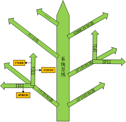
Figure 23.1.1 schematic diagram of equipment tree structure
In figure 23.1.1, the trunk of the tree is the system bus, and IIC controller, GPIO controller and SPI controller are all branches connected to the main line of the system. IIC controllers are divided into IIC1 and IIC2, of which IIC1 is connected with FT5206 and AT24C02, and IIC2 is only connected with MPU6050. The main function of DTS file is to describe the device information on the board according to the structure shown in figure 23.1.1. DTS file describes the device information with corresponding syntax rules. We will explain the DTS syntax rules in detail later.
In 3 X Version (I can't verify which version) the ARM architecture in the previous Linux kernel did not adopt the device tree. How does Linux describe the board level information in the ARM architecture when there is no device tree? In the Linux kernel source code, there are a large number of arch / ARM / Mach XXX and arch / ARM / plat XXX folders. The files in these folders are the board level information under the corresponding platform. For example, in arch / ARM / mach-s3c24xx / mach-smdk2440 C includes the following contents (with reduction):
Example code 23.1.1  mach-smdk2440.c File code snippet
90  static struct s3c2410fb_display smdk2440_lcd_cfg __initdata = {
91
92      .lcdcon5    = S3C2410_LCDCON5_FRM565 |
93                S3C2410_LCDCON5_INVVLINE |
94                S3C2410_LCDCON5_INVVFRAME |
95                S3C2410_LCDCON5_PWREN |
96                S3C2410_LCDCON5_HWSWP,
......
113 };
114
115 static struct s3c2410fb_mach_info smdk2440_fb_info __initdata = {
116     .displays   = &smdk2440_lcd_cfg,
117     .num_displays   = 1,
118     .default_display = 0,
......
133 };
134
135 static struct platform_device *smdk2440_devices[] __initdata = {
136     &s3c_device_ohci,
137     &s3c_device_lcd,
138     &s3c_device_wdt,
139     &s3c_device_i2c0,
140     &s3c_device_iis,
141 };
The structure variable SMDK2440 in the above code_ fb_ Info is the structure pointer array SMDK2440 that describes the LCD information on the development board SMDK2440_ SMDK2440 described by devices all platform related information on this development board. This is only the LCD information under the SMDK2440 development board using the chip 2440. The SMDK2440 development board also has a lot of other peripheral hardware and platform hardware information. There are many boards using the 2440 chip. Each board has a file describing the corresponding board level information. This is just a 2440. With the development of smart phones, there are at least dozens or even hundreds of new ARM architecture chips every year. The board level information files under the Linux kernel will grow exponentially! These board level information files are C or h files will be hard coded into the Linux kernel, resulting in the "puffiness" of the Linux kernel. It's like you like to eat a buffet, and then spend more than 100 yuan to a very good cafeteria. As a result, you don't want much steak, seafood and barbecue. They are all cold dishes, fried noodles, watermelon, drinks and other snacks. I'm sure you'll blurt out "Fk!" "Liar!". Similarly, when linus, the father of Linux, saw that the ARM community had added a large number of "useless" and redundant board level information files to the Linux kernel, he couldn't help but say "This whole ARM thing is a fcking pain in the ass". Since then, ARM community has introduced the flat device tree that has been adopted in PowerPC and other architectures to separate these contents describing board level hardware information from Linux and describe them in an exclusive file format. This exclusive file is called the device tree and the file extension is dts. An SOC can make many different boards. These different boards must have common information. Extract these common information as a general file, others DTS file can directly reference this general file, which is dtsi file, similar to the header file in C language. Average DTS describes board level information (that is, which IIC devices and SPI devices are on the development board) dtsi describes SOC level information (that is, how many CPU s the SOC has, what is the main frequency, information of each peripheral controller, etc.).
This is the origin of the device tree. In short, there are too many redundant garbage board level information files under the ARM architecture in the Linux kernel, which led to linus's anger. Then the ARM community introduced the device tree.
23.2 DTS, DTB and DTC
As mentioned in the previous section, the source file extension of the device tree is DTS, but we have been using it when Porting Linux DTB files. What is the relationship between DTS and DTB files? DTS is the source code file of the device tree, and DTB is the binary file obtained after DTS is compiled. Will c file compiled as o if gcc compiler is needed, it will DTS is compiled into DTB needs DTC tool! The source code of DTC tool is in the scripts/dtc directory of Linux kernel. The contents of scripts/dtc/Makefile are as follows:
Example code 23.2.1 scripts/dtc/Makefile File code snippet
4  hostprogs-$(CONFIG_DTC) := dtc
5  always       := $(hostprogs-y)
6
7  dtc-objs := dtc.o flattree.o fstree.o data.o livetree.o treesource.o
8           srcpos.o checks.o util.o
9  dtc-objs += dtc-lexer.lex.o dtc-parser.tab.o
......
As you can see, DTC Tools depend on dtc.c,flattree.c,fstree.c And other files, and finally compile and link them out DTC This host file. If you want to compile DTS File, you just need to enter Linux Under the root directory of the source code, and then execute the following command:
make all
Or:
make dtbs
The "make all" command compiles everything in the Linux source code, including uImage ko driver module and device tree. If only compiling the device tree, it is recommended to use the "make dtbs" command, "make dtbs" will compile all the selected device tree files. If you only need to compile a specified device tree, such as "stm32mp157d-ed1.dts" officially written by ST, you can enter the following command:
make stm32mp157d-ed1.dtb
The results are shown in figure 23.2.1:

Figure 23.2.1 compiling a separate device tree
There are many kinds of SoC Based on ARM architecture. One SOC can produce many boards. Each board has a corresponding DTS file. So how to determine which DTS file to compile? Let's take the board corresponding to STM32MP1 chip as an example. Open arch/arm/boot/dts/Makefile, as follows:
Example code 23.2.2 arch/arm/boot/dts/Makefile File code snippet
981 dtb-$(CONFIG_ARCH_STM32) += \
982     stm32f429-disco.dtb \
983     stm32f469-disco.dtb \
984     stm32f746-disco.dtb \
985     stm32f769-disco.dtb \
986     stm32429i-eval.dtb \
987     stm32746g-eval.dtb \
988     stm32h743i-eval.dtb \
989     stm32h743i-disco.dtb \
990     stm32mp157a-avenger96.dtb \
991     stm32mp157a-dk1.dtb \
992     stm32mp157d-dk1.dtb \
993     stm32mp157c-dk2.dtb \
994     stm32mp157f-dk2.dtb \
995     stm32mp157c-dk2-a7-examples.dtb \
996     stm32mp157c-dk2-m4-examples.dtb \
997     stm32mp157f-dk2-a7-examples.dtb \
998     stm32mp157f-dk2-m4-examples.dtb \
999     stm32mp157a-ed1.dtb \
1000    stm32mp157c-ed1.dtb \
1001    stm32mp157d-ed1.dtb \
1002    stm32mp157f-ed1.dtb \
1003    stm32mp157a-ev1.dtb \
1004    stm32mp157c-ev1.dtb \
1005    stm32mp157d-ev1.dtb \
1006    stm32mp157f-ev1.dtb \
1007    stm32mp157d-atk.dtb \
1008    stm32mp157c-ev1-a7-examples.dtb \
1009    stm32mp157c-ev1-m4-examples.dtb \
1010    stm32mp157f-ev1-a7-examples.dtb \
1011    stm32mp157f-ev1-m4-examples.dtb
It can be seen that after the SOC STM32MP1 is selected (CONFIG_ARCH_STM32=y), all boards using the SOC STM32MP1 correspond dts files are compiled into dtb. If we use STM32MP1 to create a new board, we only need to create a new one corresponding to this board dts file, and then the corresponding Add the DTB file name to DTB - $(config_arch_stm32), so that the corresponding will be added when compiling the device tree dts is compiled into binary DTB file.
Line 1007 in example code 23.2.2 is the device tree we added when Porting Linux system to the development board of punctual atom. About How to use dtb files will not be discussed here. When explaining TF-A porting, uboot porting and Linux kernel porting, how to use dtb files has been mentioned countless times dtb file (in uboot, use the bootz or bootm command to pass binary device tree file (. dtb) to the Linux kernel).
23.3 DTS syntax
Although we basically won't rewrite one from beginning to end DTS files are mostly directly provided by SOC manufacturers Modify on DTS file. However, we still need to learn the DTS file syntax in detail, because it must be modified in the follow-up work DTS file. Don't think it will be very complicated to learn new grammar. DTS grammar is very humanized. It is an ASCII text file, which is very convenient to read or modify.
In this section, we use stm32mp157d ATK Take the DTS file as an example to explain the DTS syntax. For the detailed syntax rules of the device tree, please refer to the two documents "Devicetree SpecificationV0.2.pdf" and "Power_ePAPR_APPROVED_v1.12.pdf". These two documents have been put into the development board CD-ROM. the path is: 4. Resources - > devicetree specificationv0 2. PDF, 4. References - > Power_ePAPR_APPROVED_v1.12.pdf
23.3.1 .dtsi header file
Like C language, the device tree also supports header files. The header file extension of the device tree is dtsi. At stm32mp157d ATK DTS contains the following contents:
Example code 23.3.1.1 stm32mp157d-atk.dts File code snippet
8  #include "stm32mp157.dtsi"
9  #include "stm32mp15xd.dtsi"
10 #include "stm32mp15-pinctrl.dtsi"
11 #include "stm32mp15xxaa-pinctrl.dtsi"
12 #include "stm32mp157-m4-srm.dtsi"
13 #include "stm32mp157-m4-srm-pinctrl.dtsi"
14 #include "stm32mp157d-atk.dtsi"
eighth~17 Line, using“#include "to reference" stm32mp15*.dtsi " dtsi header file.
In the device tree, in addition to“#include " dtsi files can also be referenced h header file, open stm32mp157f-dk2 DTS file, find the following code:
Example code 23.3.1.2 stm32mp157f-dk2 DTS file code snippet
14 #include <dt-bindings/rtc/rtc-stm32.h>
The. dts file can not only be used in C language h header files can even be referenced dts file, open stm32mp157c-ev1 dts file, which contains the following contents:
Example code 23.3.1.3 stm32mp157c-ev1 DTS file code snippet
8 #include "stm32mp157c-ed1.dts"
As you can see, the example code 23.3.1.3 directly refers to dts file, so in dts device tree file can be referenced by "#include" h,. And dtsi dts file. However, we have the best choice when writing the device tree header file Dtsi suffix.
Average Dtsi file is used to describe the internal and peripheral information of SOC, such as CPU architecture, main frequency, peripheral register address range, such as UART, IIC, etc. If there are more than one SOC in a series, the same internal and peripheral information will be extracted into one Dtsi file, so as to reduce the redundancy of code. At present, stm32mp151, stm32mp153 and stm32mp157 are three SOCS in stm32mpp1 series, of which 151 has the least peripherals, and the peripherals of 153 and 157 are gradually increased on the basis of 151. Therefore, 151 is equivalent to "base class", and 153 and 157 are "derived classes" based on 151. Therefore, ST writes the most basic peripheral resources in stm32mp151 In the dtsi file. stm32mp151.dtsi describes the peripheral information shared by 151, 153 and 157 as follows:
Example code 23.3.1.4 stm32mp151.dtsi File code snippet
6   #include <dt-bindings/interrupt-controller/arm-gic.h>
7   #include <dt-bindings/clock/stm32mp1-clks.h>
8   #include <dt-bindings/gpio/gpio.h>
9   #include <dt-bindings/reset/stm32mp1-resets.h>
10  #include <dt-bindings/thermal/thermal.h>
11
12
13  / {
14      #address-cells = <1>;
15      #size-cells = <1>;
16
17      cpus {
18          #address-cells = <1>;
19          #size-cells = <0>;
20
21          cpu0: cpu@0 {
22              compatible = "arm,cortex-a7";
......
29              nvmem-cell-names = "part_number";
30              #cooling-cells = <2>;
31          };
32      };
33
34      cpu0_opp_table: cpu0-opp-table {
35          compatible = "operating-points-v2";
36          opp-shared;
37      };
38  };
......
469         spi2: spi@4000b000 {
470             #address-cells = <1>;
471             #size-cells = <0>;
472             compatible = "st,stm32h7-spi";
473             reg = <0x4000b000 0x400>;
474             interrupts = <GIC_SPI 36 IRQ_TYPE_LEVEL_HIGH>;
475             clocks = <&rcc SPI2_K>;
476             resets = <&rcc SPI2_R>;
477             dmas = <&dmamux1 39 0x400 0x01>,
478                    <&dmamux1 40 0x400 0x01>;
479             dma-names = "rx", "tx";
480             power-domains = <&pd_core>;
481             status = "disabled";
482         };
Line 1733 in example code 23.3.1.4 is the device node information of CPU0. This node information describes the CPU information used by STM32MP151 SOC, such as the architecture is cortex-A7,CPU clock, etc. STM32MP151 The dtsi file not only describes the node information of CPU0, but also all peripherals of STM32MP151 SOC, such as SAI14, U(S)ART18, SDIO13, etc. we will explain the specific contents of these device node information in detail in the specific chapters later.
23.3.2 equipment node
The device tree is a file that uses a tree structure to describe the device information on the board. Each device is a node called a device node. Each node describes the node information through some attribute information. The attribute is a key value pair. The following documents are the contents of the equipment tree documents reduced in combination with the official equipment tree of ST:
Example code 23.3.2.1 Device tree template
1   / {
2       #address-cells = <1>;
3       #size-cells = <1>;
4
5       aliases {
6            serial0 = &uart4;
7       };
8
9       cpus {
10          #address-cells = <1>;
11          #size-cells = <0>;
12
13          cpu0: cpu@0 {
14              compatible = "arm,cortex-a7";
15              device_type = "cpu";
16              reg = <0>;
17              clocks = <&scmi0_clk CK_SCMI0_MPU>;
18              clock-names = "cpu";
19              operating-points-v2 = <&cpu0_opp_table>;
20              nvmem-cells = <&part_number_otp>;
21              nvmem-cell-names = "part_number";
22              #cooling-cells = <2>;
23          };
24      };
25
26      soc {
27          compatible = "simple-bus";
28          #address-cells = <1>;
29          #size-cells = <1>;
30          interrupt-parent = <&intc>;
31          ranges;
32
33          sram: sram@10000000 {
34              compatible = "mmio-sram";
35              reg = <0x10000000 0x60000>;
36              #address-cells = <1>;
37              #size-cells = <1>;
38              ranges = <0 0x10000000 0x60000>;
39          };
40      };
41  };
In line 1, "/" is the root node, and each device tree file has only one root node. Careful students should find that when transplanting the device tree from the kernel, we created stm32mp157d ATK DTS and stm32mp157d ATK Dtsi these two files have a "/" root node. Will there be no error? No, because the contents of the two "/" root nodes will be merged into one root node.
In lines 5, 9 and 26, aliases, cpus and soc are the three child nodes, and in line 33, sram is the child node of soc. In the device tree, the node naming format is as follows:
node-name@unit-address
"Node name" is the node name, which is an ASCII string. The node name should clearly describe the function of the node. For example, "uart1" means that the node is a uart1 peripheral. "Unit address" generally refers to the address of the device or the first address of the register. If a node does not have an address or register, "unit address" can be omitted, for example“ cpu@0 ”,“ sram@10000000 ”,“soc”.
However, in the example code 23.3.2.1, we can see the node naming as follows:
cpu0:cpu@0
The above command is not "node"- name@unit -The format of "address" is separated into two parts by ":". Before ":" is the node label, and after ":" is the node name. The format is as follows:
label: node-name@unit-address
The purpose of introducing label is to facilitate access to the node. You can access this node directly through & label, such as through & cpu0“ cpu@0 ”This node, without entering the full node name. Another example is the node "sram: sram@10000000 ”, the node label is SRAM, and the node name is very long“ sram@10000000 ”. It is obvious to access through & SRAM“ sram@10000000 ”This node is much more convenient!
In line 13, cpu0 is also a node, but cpu0 is a child node of cpus.
Each node has different attributes, and different attributes have different contents. Attributes are key value pairs, and the value can be empty or any byte stream. Several data forms commonly used in the source code of the device tree are as follows:
1. String
compatible = "arm,cortex-a7";
The above code sets the value of the compatible attribute to the string "arm,cortex-a7".
2. 32-bit unsigned integer
reg = <0>;
The above code sets the value of reg attribute to 0, and the value of reg can also be set to a group of values, such as:
reg = <0 0x123456 100>;
3. String list
The attribute value can also be a string list, separated by "," between strings, as shown below:
compatible = "st,stm32mp157d-atk", "st,stm32mp157";
The above code sets the value of the attribute compatible as "St, stm32mp157d ATK" and "st,stm32mp157".
23.3.3 standard attributes
Nodes are composed of a pile of attributes. Nodes are specific devices. Different devices need different attributes. Users can customize the attributes. In addition to user-defined attributes, many attributes are standard attributes, which are used by many peripheral drivers under Linux. In this section, we will learn some common standard attributes.
1. compatible attribute
The compatible attribute is also called the "compatibility" attribute, which is a very important attribute! The value of the compatible attribute is a list of strings. The compatible attribute is used to bind the device and driver. The string list is used to select the driver to be used by the device. The value format of the compatible attribute is as follows:
"manufacturer,model"
Manufacturer refers to the manufacturer, and model is generally the driver name corresponding to the module. For example, stm32mp15xx dkx There is an audio device node in dtsi. The audio chip of this node adopts cs42l51 produced by Cirrus Logic company. The compatible attribute values are as follows:
compatible = "cirrus,cs42l51";
The attribute value is "cirrus,cs42l51", where "cirrus" indicates that the manufacturer is Cirrus Logic and "cs42l51" indicates the name of the driver module. compatible can also multiple attribute values. For example:
compatible = "cirrus,my_cs42l51","cirrus,cs42l51";
In this way, our device has two attribute values. First, the device uses the first compatible value to search in the Linux kernel to see if it can find the matching driver file. If not, use the second compatible value to check, and so on until all the values in the compatible attribute are found.
Generally, the driver file will have an OF matching table, which stores some compatible values. If the compatible attribute value OF the device node is equal to any value in the OF matching table, it means that the device can use the driver. For example, in the file cs42l51 C includes the following:
Example code 23.3.3.1 cs42l51.c File code snippet
799 const struct of_device_id cs42l51_of_match[] = {
800     { .compatible = "cirrus,cs42l51", },
801     { }
802 };
array cs42l51_of_match namely cs42l51.c The matching table of this driver file. This matching table has only one matching value“ cirrus,cs42l51". If there is a node in the device tree compatible If the attribute value is equal to this, this node will use this driver file.
2. model property
The model attribute value is also a string. Generally, the model attribute describes the name of the development board or equipment module information, such as the name, such as:
model = "STMicroelectronics STM32MP157C-DK2 Discovery Board";
3. status attribute
The status attribute is related to the device status according to the name. The value of the status attribute is also a string. The string is the status information of the device. The optional status is shown in table 23.3.3.1:
Value description
"okay" indicates that the device is operable.
"Disabled" indicates that the device is currently inoperable, but can become operable in the future, such as after the hot plug device is inserted. The specific meaning of disabled depends on the binding document of the device.
"fail" indicates that the device is inoperable, the device has detected a series of errors, and the device is unlikely to become operable.
"Fail sss" has the same meaning as "fail", and the following sss part is the detected error content.
Table 23.3.3.1 status attribute value table
4. #address cells and #size cells properties
The values of these two attributes are unsigned 32-bit shaping, #address cells and #size cells can be used in any device with child nodes to describe the address information of child nodes# The address cells attribute value determines the word length (32 bits) occupied by the address information in the reg attribute of the child node, #size cells attribute value determines the word length (32 bits) occupied by the length information in the reg attribute of the child node# Address cells and #size cells indicate how the child node should write the value of the reg attribute. Generally, the reg attribute is related to the address. There are two kinds of information related to the address: the starting address and the address length. The format of the reg attribute is:
reg = <address1 length1 address2 length2 address3 length3......>
Each "address length" combination represents an address range, where address is the starting address, length is the address length, #address cells indicates the word length occupied by the address data, #size cells indicates the word length occupied by the length data, such as:
Example code 23.3.3.2 #address-cells and#Size cells attribute
1   cpus {
2       #address-cells = <1>;
3       #size-cells = <0>;
4
5       cpu0: cpu@0 {
6           compatible = "arm,cortex-a7";
7           device_type = "cpu";
8           reg = <0>;
9           clocks = <&scmi0_clk CK_SCMI0_MPU>;
10          clock-names = "cpu";
11          operating-points-v2 = <&cpu0_opp_table>;
12          nvmem-cells = <&part_number_otp>;
13          nvmem-cell-names = "part_number";
14          #cooling-cells = <2>;
15      };
16  };
17
18  scmi_sram: sram@2ffff000 {
19      compatible = "mmio-sram";
20      reg = <0x2ffff000 0x1000>;
21      #address-cells = <1>;
22      #size-cells = <1>;
23      ranges = <0 0x2ffff000 0x1000>;
24
25      scmi0_shm: scmi_shm@0 {
26          reg = <0 0x80>;
27      };
28  };
In lines 2 and 3, #address cells = < 1 >, #size cells = < 0 > of cpus indicates that the word length occupied by the starting address in the reg attribute of cpus child node is 1 and the word length occupied by the address length is 0.
Line 8, child node cpu0: cpu@0 The reg attribute value of is < 0 >, because the parent node has set #address cells = < 1 >, #size cells = < 0 >, so addres=0 and there is no value of length, which is equivalent to setting the starting address without setting the address length.
Lines 21 and 22, set the scmi_sram: sram@02ffff000 Node #address cells = < 1 >, #size cells = < 1 >, indicating scmi_sram: sram@02ffff000 The word length occupied by the node starting address length is 1, and the word length occupied by the address length is also 1.
Line 26, child node scmi0_shm: scmi_shm@0 The reg attribute value of is < 0x0 0x80 >, because the parent node has set #address cells = < 1 >, #size cells = < 1 >, address= 0x0, length= 0x80, which is equivalent to setting the starting address as 0x0 and the address length as 0x80.
5. reg attribute
As mentioned earlier, the value of reg attribute is generally (address, length) pair. Reg attribute is generally used to describe device address space resource information or device address information, such as register address range information of a peripheral, or device address of IIC device, such as stm32mp151 Dtsi includes the following contents:
Example code 23.3.3.3 uart5 Node information
576             uart5: serial@40011000 {
577                 compatible = "st,stm32h7-uart";
578                 reg = <0x40011000 0x400>;
579                 interrupts-extended = <&exti 31 IRQ_TYPE_LEVEL_HIGH>;
580                 clocks = <&rcc UART5_K>;
581                 resets = <&rcc UART5_R>;
582                 wakeup-source;
583                 power-domains = <&pd_core>;
584                 dmas = <&dmamux1 65 0x400 0x5>,
585                        <&dmamux1 66 0x400 0x1>;
586                 dma-names = "rx", "tx";
587                 status = "disabled";
588             };
The uart5 node describes the uart5 related information of stm32mp1 series chips, focusing on the reg attribute in line 578. Because the parent node "soc" of uart5 has #address cells = < 1 >, #size cells = < 1 >, address=0x40011000 and length=0x400 in reg attribute. Referring to the reference manual of stm32mp157, we can see that the first address of uart5 register of stm32mp157 chip is 0x40011000, but the address length (range) of uart5 is not as much as 0x400. Here we focus on obtaining the first address of uart5 register.
6. ranges attribute
The ranges attribute value can be null or a numeric matrix written in the format of (child bus address, parent bus address, length). Ranges is an address mapping / conversion table. Each item of the ranges attribute is composed of three parts: child address, parent address and address space length:
Child bus address: the physical address of the child bus address space. The word length occupied by this physical address is determined by the #address cells of the parent node.
Parent bus address: the physical address of the parent bus address space. The word length occupied by this physical address is also determined by the #address cells of the parent node.
Length: the length of the child address space. The word length occupied by the address length is determined by the #size cells of the parent node.
If the ranges attribute value is null, it means that the child address space and the parent address space are exactly the same, and address translation is not required. For the stm32mp157 we use, the child address space and the parent address space are exactly the same, so it will be in stm32mp151 A large number of ranges attributes with empty values were found in dtsi, as shown below:
Example code 23.3.3.4 stm32mp151.dtsi File code snippet
192         soc {
193             compatible = "simple-bus";
194             #address-cells = <1>;
195             #size-cells = <1>;
196             interrupt-parent = <&intc>;
197             ranges;
......
1968        };
Line 197 defines the ranges attribute, but the range attribute value is empty.
The example code where the ranges attribute is not empty is as follows:
Example code 23.3.3.5 ranges Property is not empty
1   soc {
2       compatible = "simple-bus";
3       #address-cells = <1>;
4       #size-cells = <1>;
5       interrupt-parent = <&intc>;
6       ranges = <0 0x10000000 0x100000>;
7
8       sram: sram@10000000 {
9           compatible = "mmio-sram";
10          reg = <0x0 0x60000>;
11          #address-cells = <1>;
12          #size-cells = <1>;
13          ranges = <0 0x10000000 0x60000>;
14      };
15  };
In line 6, the ranges attribute defined by the node soc is < 0 0x10000000 0x100000 >, which specifies an address range of 1024KB(0x100000). The physical start address of the child address space is 0 and the physical start address of the parent address space is 0x10000000.
In line 8, sram is the internal RAM node of STM32MP1. The reg attribute defines that the starting address of the sram device register is 0 and the register length is 0x60000. After address translation, sram device can start reading and writing from 0x10000000, 0x10000000=0x0 + 0x10000000.
7. name attribute
The value of the name attribute is a string. The name attribute is used to record the node name. The name attribute has been deprecated and is not recommended. Some old device tree files may use this attribute.
8,device_type attribute
device_ The value of the type attribute is a string. IEEE 1275 will use this attribute to describe the FCode of the device, but there is no FCode in the device tree, so this attribute is also discarded. This attribute can only be used for CPU nodes or memory nodes. Stm32mp151. The cpu0 node of dtsi uses this attribute. The contents are as follows:
Example code 23.3.3.6 stm32mp151.dtsi File code snippet
21          cpu0: cpu@0 {
22              compatible = "arm,cortex-a7";
23              device_type = "cpu";
......
32      	};
There are so many explanations about standard attributes. Other standard attributes used, such as interrupt, IIC, SPI, etc., will be explained after specific routines.
23.3.4 root node compatible attribute
Each node has a compatible attribute, and the root node "/" is no exception. In our new stm32mp157d ATK The content of the compatible attribute of the root node in the DTS file is as follows:
Example code 23.3.4.1 stm32mp157d-atk.dts Root node compatible attribute
16  / {
17      model = "STMicroelectronics STM32MP157C-DK2 Discovery Board";
18      compatible = "st,stm32mp157d-atk", "st,stm32mp157";
......
41  };
It can be seen that there are two values of "mst-357k, mst-32k". As we said earlier, the compatible attribute value of the device node is to match the driver in the Linux kernel. What does the compatible attribute in the root node do? We can know the device we use through the compatible attribute of the root node. Generally, the first value describes the name of the hardware device used, for example, "stm32mp157d ATK" is used here, and the second value describes the SOC used by the device, for example, "stm32mp157" is used here. The Linux kernel will check whether the device is supported through the compatible attribute of the root node. If so, the device will start the Linux kernel. Next, let's learn how the Linux kernel determines whether to support a device before and after using the device tree.
1. Device matching method before using device tree
Before using the device tree, uboot will pass a value called machine id to the Linux kernel. machine id is the device ID, which tells the Linux kernel what device it is and whether the Linux kernel supports it. The Linux kernel supports many devices. For each device (board), the Linux kernel uses MACHINE_START and MACHINE_END to define a machine_desc structure to describe the device, for example, in the file arch / arm / Mach IMX / mach-mx35_ 3ds. C has the following definitions:
Example code 23.3.4.2 MX35_3DS equipment
506 MACHINE_START(MX35_3DS, "Freescale MX35PDK")
507     /* Maintainer: Freescale Semiconductor, Inc */
508     .atag_offset = 0x100,
509     .map_io = mx35_map_io,
510     .init_early = imx35_init_early,
511     .init_irq = mx35_init_irq,
512     .init_time  = mx35pdk_timer_init,
513     .init_machine = mx35_3ds_init,
514     .reserve = mx35_3ds_reserve,
515     .restart    = mxc_restart,
516 MACHINE_END
The above code is the definition“ Freescale MX35PDK"This device, where MACHINE_START and MACHINE_END Defined in file arch/arm/include/asm/mach/arch.h The contents are as follows:
Example code 23.3.4.3 MACHINE_START and MACHINE_END Macro definition
81 #define MACHINE_START(_type,_name)           \
82 static const struct machine_desc __mach_desc_##_type \
83  __used                          \
84  __attribute__((__section__(".arch.info.init"))) = { \
85  .nr     = MACH_TYPE_##_type,        \
86  .name       = _name,
87
88 #define MACHINE_END              \
89
according to MACHINE_START and MACHINE_END For the macro definition of, sample code 23.3.4.2 After expansion, it is as follows:
Example code 23.3.4.3 After expansion
1  static const struct machine_desc __mach_desc_MX35_3DS    	\
2   	__used                          								\
3   	__attribute__((__section__(".arch.info.init"))) = {
4   	.nr     = MACH_TYPE_MX35_3DS,
5   	.name       = "Freescale MX35PDK",
6   	/* Maintainer: Freescale Semiconductor, Inc */
7   	.atag_offset = 0x100,
8   	.map_io = mx35_map_io,
9   	.init_early = imx35_init_early,
10 	 	.init_irq = mx35_init_irq,
11  	.init_time  = mx35pdk_timer_init,
12  	.init_machine = mx35_3ds_init,
13  	.reserve = mx35_3ds_reserve,
14  	.restart    = mxc_restart,
15 };
From example code 23.3.4.3 As you can see, here is a definition machine_desc Structure variable of type__mach_desc_MX35_3DS,This variable is stored in“.arch.info.init"Paragraph. On line 4 MACH_TYPE_MX35_3DS That's it“ Freescale MX35PDK"This board is machine id. MACH_TYPE_MX35_3DS Defined in file include/generated/mach-types.h In, this file defines a large number of machine id,The contents are as follows:
Example code 23.3.4.3 mach-types.h In the file machine id
10 	  #define MACH_TYPE_EBSA110           	0
11 	  #define MACH_TYPE_RISCPC               	1
12    #define MACH_TYPE_NEXUSPCI            	3
......
1629 #define MACH_TYPE_MX35_3DS            	1645
......
5053 #define MACH_TYPE_OMAP3_MRC3D        	5114
Line 1629 is MACH_TYPE_MX35_3DS The value of is 1645.
As I said earlier, uboot Will give Linux Kernel transfer machine id This parameter, Linux The kernel will check this machine id,In fact, it is to machine id With example code 23.3.4.3 These in MACH_TYPE_XXX Compare macros to see if they are equal. If they are equal, it means Linux The kernel supports this device. If it is not supported, the device cannot be started Linux Kernel.
2,Device matching method after using device tree
 When Linux After the kernel introduces the device tree, it is no longer used MACHINE_START Instead, instead DT_MACHINE_START. DT_MACHINE_START Also defined in the file arch/arm/include/asm/mach/arch.h Inside, it is defined as follows:
Example code 23.3.4.4 DT_MACHINE_START macro
91 #define DT_MACHINE_START(_name, _namestr)        \
92 static const struct machine_desc __mach_desc_##_name \
93  __used                          \
94  __attribute__((__section__(".arch.info.init"))) = { \
95  .nr     = ~0,               \
96  .name       = _namestr,
97
98 #endif
As can be seen, DT_MACHINE_START and MACHINE_START is basically the same, except nr is set differently in DT_MACHINE_START will be directly in the nr is set to ~ 0. Note that after the introduction of the device tree, the Linux kernel will no longer check whether it supports a device according to the machine id.
Open the file arch / arm / mach-stm32 / board DT c. The contents are as follows:
Example code 23.3.4.5 stm32mp157 equipment
14  static const char *const stm32_compat[] __initconst = {
15      "st,stm32f429",
16      "st,stm32f469",
17      "st,stm32f746",
18      "st,stm32f769",
19      "st,stm32h743",
20      "st,stm32mp151",
21      "st,stm32mp153",
22      "st,stm32mp157",
23      NULL
24  };
25
26  DT_MACHINE_START(STM32DT, "STM32 (Device Tree Support)")
27      .dt_compat = stm32_compat,
28  #ifdef CONFIG_ARM_SINGLE_ARMV7M
29      .restart = armv7m_restart,
30  #endif
31  MACHINE_END
machine_ There are in desc structure dt_compat member variable, which holds the compatibility attribute of the device, set in example code 23.3.4.5 dt_compat is stm32_compat, which contains the soc compatibility values supported by the Linux kernel. As long as the compatible attribute value of a device (board) root node "/" is the same as STM32_ If any value in the compat table is equal, it means that the Linux kernel supports this device. stm32mp157d-atk. The compatible attribute value of the root node in DTS is as follows:
compatible = "st,stm32mp157d-atk", "st,stm32mp157";
Where "st,stm32mp157" and stm32_ "st,stm32mp157" in compat matches, so the punctual atom STM32MP157 development board can start the Linux kernel normally.
Next, let's take a brief look at how the Linux kernel matches the corresponding machine according to the compatible attribute of the root node of the device tree_ DESC, the Linux kernel calls start_kernel function to start the kernel, start_ The kernel function calls setup_arch function to match machine_desc,setup_ The arch function is defined in the file arch / arm / kernel / setup In C, the function contents are as follows (with reduction):
Example code 23.3.4.6 setup_arch Function content
1076    void __init setup_arch(char **cmdline_p)
1077    {
1078        const struct machine_desc *mdesc;
1079
1080        setup_processor();
1081        mdesc = setup_machine_fdt(__atags_pointer);
1082        if (!mdesc)
1083            mdesc = setup_machine_tags(__atags_pointer,
__machine_arch_type);
......
1094        machine_desc = mdesc;
1095        machine_name = mdesc->name;
......
1174    }
Line 1081, call setup_machine_fdt function to get the matching machine_desc, the parameter is the first address of atags, that is, the first address of dtb file passed from uboot to Linux kernel, setup_ machine_ The return value of the FDT function is the most matching machine found_ desc.
Function setup_machine_fdt is defined in the file arch / arm / kernel / devtree In C, the contents are as follows (with reduction):
Example code 23.3.4.7 setup_machine_fdt Function content
211 const struct machine_desc * __init setup_machine_fdt(unsigned int dt_phys)
212 {
213     const struct machine_desc *mdesc, *mdesc_best = NULL;
......
224     if (!dt_phys || !early_init_dt_verify(phys_to_virt(dt_phys)))
225         return NULL;
226
227     mdesc = of_flat_dt_match_machine(mdesc_best,
                           arch_get_next_mach);
......
256     __machine_arch_type = mdesc->nr;
257
258     return mdesc;
259 }
Line 227, call the function of_flat_dt_match_machine to get the matching machine_desc, parameter mdesc_best is the default machine_desc, parameter arch_get_next_mach is a function defined in arch / arm / kernel / devtree C in the document. Find matching machine_desc process is to use the compatible attribute value of the root node of the device tree and all machines saved in the Linux kernel_ Desc structure dt_ Compare the values in compat to see if they are equal. If they are equal, it means that a matching machine is found_ desc,arch_ get_ next_ The job of the Mach function is to get the next machine in the Linux kernel_ Desc structure.
Finally, let's take a look_ flat_ dt_ match_ Machine function, which is defined in the file drivers / of / FDT In C, the contents are as follows (with reduction):
Example code 23.3.4.8 of_flat_dt_match_machine Function content
815     const void * __init of_flat_dt_match_machine(const void *default_match,
816             const void * (*get_next_compat)(const char * const**))
817     {
818         const void *data = NULL;
819         const void *best_data = default_match;
820         const char *const *compat;
821         unsigned long dt_root;
822         unsigned int best_score = ~1, score = 0;
823
824         dt_root = of_get_flat_dt_root();
825         while ((data = get_next_compat(&compat))) {
826             score = of_flat_dt_match(dt_root, compat);
827             if (score > 0 && score < best_score) {
828                 best_data = data;
829                 best_score = score;
830             }
831         }
.....
850         pr_info("Machine model: %s\n", of_flat_dt_get_machine_name());
851
852         return best_data;
853     }
Line 824, through the function of_get_flat_dt_root gets the root node of the device tree.
Lines 825 to 831, this loop is to find the matching machine_desc procedure, of on line 826_ flat_ dt_ The match function will match the value of the compatible attribute of the root node with each machine_desc structure dt_ Compare the value of compat until the matching machine is found_ desc.
To sum up, the Linux kernel finds the function call process of the corresponding device through the compatible attribute of the root node, as shown in figure 23.3.4.2:
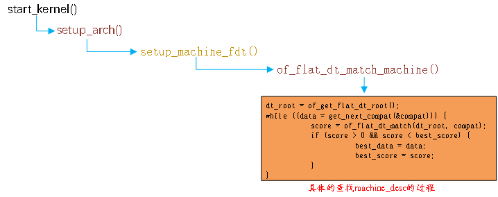
Figure 23.3.4.2 process of finding matching equipment
23.3.5 adding or modifying content to nodes
The product development process may face frequent demand changes, such as the six axis chip MPU6050 with an IIC interface on the first version of hardware, and the MPU6050 will be replaced with MPU9250 in the second version of hardware. Once the hardware is modified, we need to modify the device tree file synchronously. After all, the device tree is a file that describes the hardware information of the board. Assuming that there is a six axis chip fxls8471, which needs to be connected to the i2c1 interface of STM32MP157D-ATK development board, it is equivalent to adding a fxls8471 child node to the i2c1 node. First take a look at the node corresponding to the i2c1 interface and open the file stm32mp151 Dtsi file, find the following:
Example code 23.3.5.1 i2c1 node
590     i2c1: i2c@40012000 {
591         compatible = "st,stm32mp15-i2c";
592         reg = <0x40012000 0x400>;
593         interrupt-names = "event", "error";
594         interrupts-extended = <&exti 21 IRQ_TYPE_LEVEL_HIGH>,
595                       <&intc GIC_SPI 32 IRQ_TYPE_LEVEL_HIGH>;
596         clocks = <&rcc I2C1_K>;
597         resets = <&rcc I2C1_R>;
598         #address-cells = <1>;
599         #size-cells = <0>;
600         dmas = <&dmamux1 33 0x400 0x80000001>,
601                <&dmamux1 34 0x400 0x80000001>;
602         dma-names = "rx", "tx";
603         power-domains = <&pd_core>;
604         st,syscfg-fmp = <&syscfg 0x4 0x1>;
605         wakeup-source;
606         status = "disabled";
607     };
Example code 23.3.5.1 is the i2c1 node of STM32MP157. Now you need to create a child node under the i2c1 node, which is fxls8471. The simplest way is to directly add a child node named fxls8471 under i2c1, as shown below:
Example code 23.3.5.2 add to fxls8471 Child node
590     i2c1: i2c@40012000 {
591         compatible = "st,stm32mp15-i2c";
592         reg = <0x40012000 0x400>;
593         interrupt-names = "event", "error";
594         interrupts-extended = <&exti 21 IRQ_TYPE_LEVEL_HIGH>,
595                       <&intc GIC_SPI 32 IRQ_TYPE_LEVEL_HIGH>;
596         clocks = <&rcc I2C1_K>;
597         resets = <&rcc I2C1_R>;
598         #address-cells = <1>;
599         #size-cells = <0>;
600         dmas = <&dmamux1 33 0x400 0x80000001>,
601                <&dmamux1 34 0x400 0x80000001>;
602         dma-names = "rx", "tx";
603         power-domains = <&pd_core>;
604         st,syscfg-fmp = <&syscfg 0x4 0x1>;
605         wakeup-source;
606         status = "disabled";
607         //fxls8471 child node
608         fxls8471@1e {
609             compatible = "fsl,fxls8471";
610                reg = <0x1e>;
611            };
612     };
Lines 608 ~ 611 are the sub nodes corresponding to the fxls8471 chip added. But there will be a problem! I2c1 node is defined in stm32mp151 In the dtsi file, while stm32mp151 Dtsi is a common device tree header file. All other boards using stm32mp1 SOC will reference stm32mp151 Dtsi this file. Adding fxls8471 directly to the i2c1 node is equivalent to adding fxls8471 to all other boards, but other boards do not have this device! Therefore, it is definitely not possible to write like this according to the example code 23.3.5.2.
Here we need to introduce another content, that is, how to add data to the node. What we need to solve now is how to add a child node named fxls8471 to the i2c1 node, and it can not affect other boards using stm32mp1. The device tree file used by STM32MP157D-ATK development board is STM32MP157D-ATK DTS and stm32mp157d ATK Dtsi, so we need stm32mp157d ATK The DTS file completes the content of data addition in the following way:
Example code 23.3.5.3 Method of adding data to nodes
1 &i2c1 {
2 	/* Content to append or modify */
3 };
Line 1,&i2c1 Indicates that you want to access i2c1 this label The corresponding node, that is stm32mp151.dtsi Medium“ i2c1: i2c@40012000".
Line 2, in curly brackets, is to i2c1 The content added by this node includes modifying the values of some attributes.
open stm32mp157d-atk.dts,Add the following code after the root node:
Example code 23.3.5.4 towards i2c1 Node append data
1   &i2c1 {
2       pinctrl-names = "default", "sleep";
3       pinctrl-0 = <&i2c1_pins_b>;
4       pinctrl-1 = <&i2c1_pins_sleep_b>;
5       status = "okay";
6       clock-frequency = <100000>;
7
8       fxls8471@1e {
9           compatible = "fsl,fxls8471";
10          reg = <0x1e>;
11          position = <0>;
12          interrupt-parent = <&gpioh>;
13          interrupts = <6 IRQ_TYPE_EDGE_FALLING>;
14      };
15  };
Example code 23.3.5.4 is to add / modify data to i2c1 node. For example, the value of status attribute in line 5 is changed from disabled to OK. The attribute "clock frequency" in line 6 indicates that the i2c1 clock is 100KHz. "Clock frequency" is the newly added attribute.
Lines 8 to 14, the sub node fxls8471 of i2c1 indicates the fxls8471 connected to i2c1. The "fxls8471" sub node describes the relevant information of the chip fxls8471.
Because the content in example code 23.3.5.4 is stm32mp157d ATK DTS is in this file, so it will not have any impact on other boards using STM32MP157 SOC. This is to add or modify content to the node. The key is to access the node through & label, and then write the content to be added or modified directly in it.
23.4 create a small template equipment tree
The syntax of dts has been explained in detail in the previous section. In this section, we will write a small device tree file from beginning to end according to the syntax explained above. Of course, this small device tree has no practical significance. The purpose of this is to master the syntax of the device tree. In actual product development, we don't need to completely rewrite one dts device tree files are generally provided by SOC manufacturers dts file, we only need to modify it according to our actual situation. Before writing a device tree, we need to define a device. Let's take STM32MP157 as an example. The contents we need to describe in the device tree are as follows:
This chip is composed of two 32-bit CPU s and Cortex-M4 with Cortex-A7 architecture.
STM32MP157 internal sram, starting address 0x10000000, size 384KB(0x60000).
STM32MP157 internal timers6, starting address 0x40004000, size 25.6KB(0x400).
STM32MP157 internal spi2, the starting address is 0x4000b000, and the size is 25.6KB(0x400).
STM32MP157, internal usart2, starting address 0x4000e000, size 25.6KB(0x400).
STM32MP157 internal i2c1, starting address 0x40012000, size 25.6KB(0x400).
For simplicity, we can implement these contents in the device tree. First, build a basic framework with only the root node "/", and create a new one named myfirst DTS file, enter the following contents in it:
Example code 23.4.1 Equipment tree basic framework
1   / {
2       compatible = "st,stm32mp157d-atk", "st,stm32mp157";
3   };
The device tree framework is very simple. There is only one root node "/, and there is only one compatible attribute in the root node. We will add the contents listed above to this basic framework.
1. Add cpus node
First, add a CPU node. STM32MP157 adopts Cortex-A7 architecture. First, add a cpus node, and add cpu0 child node and cpu1 child node under the cpus node. After completion, it is as follows:
Example code 23.4.2 add to cpus node
1   / {
2       compatible = "st,stm32mp157d-atk", "st,stm32mp157";
3       /* cpus node */
4       cpus {
5           #address-cells = <1>;
6           #size-cells = <0>;
7
8           /* CPU0 node */
9           cpu0: cpu@0 {
10              compatible = "arm,cortex-a7";
11              device_type = "cpu";
12              reg = <0>;
13          };
14          /* CPU1 node */
15          cpu1: cpu@1 {
16              compatible = "arm,cortex-a7";
17              device_type = "cpu";
18              reg = <1>;
19          };
20      };
21  };
Lines 4-20 are cpus node, which is used to describe all cpus in SOC. Since STM32MP157 has two cpus, two child nodes are added under cpus, cpu0 and cpu1 respectively.
2. Add soc node
uart, iic controller and so on belong to SOC internal peripherals. Therefore, a parent node called SOC is generally created to manage the child nodes of these SOC internal peripherals, and myfirst after adding SOC nodes DTS file contents are as follows:
Example code 23.4.3 add to soc node
1   / {
2       compatible = "st,stm32mp157d-atk", "st,stm32mp157";
3       /* cpus node  */
4       cpus {
5           #address-cells = <1>;
6           #size-cells = <0>;
7
8           /* CPU0 node */
9           cpu0: cpu@0 {
10              compatible = "arm,cortex-a7";
11              device_type = "cpu";
12              reg = <0>;
13          };
14          /* CPU1 node */
15          cpu1: cpu@1 {
16              compatible = "arm,cortex-a7";
17              device_type = "cpu";
18              reg = <1>;
19          };
20      };
21      /* soc node */
22      soc {
23          compatible = "simple-bus";
24          #address-cells = <1>;
25          #size-cells = <1>;
26          ranges;
27      };
28  };
Lines 22 to 27 are soc nodes. soc nodes set #address cells = < 1 >, #size cells = < 1 >, so that the reg attribute of soc child nodes initially occupies a word length, and the length of address space also occupies a word length.
In line 26, the ranges attribute is empty, indicating that the address range of the subspace and the parent space are the same.
3. Add sram node
We continue to add SRAM node. SRAM is the internal RAM of STM32MP157, and SRAM4 will be used in M4 kernel. SRAM is the child node of soc node. The starting address of SRAM is 0x10000000 and the size is 384KB. After adding SRAM node, myfirst DTS file contents are as follows:
Example code 23.4.4 add to sram node
1   / {
2       compatible = "st,stm32mp157d-atk", "st,stm32mp157";
3       /* cpus node */
4       cpus {
5           #address-cells = <1>;
6           #size-cells = <0>;
7
8           /* CPU0 node */
9           cpu0: cpu@0 {
10              compatible = "arm,cortex-a7";
11              device_type = "cpu";
12              reg = <0>;
13          };
14          /* CPU1 node */
15          cpu1: cpu@1 {
16              compatible = "arm,cortex-a7";
17              device_type = "cpu";
18              reg = <1>;
19          };
20      };
21      /* soc node  */
22      soc {
23          compatible = "simple-bus";
24          #address-cells = <1>;
25          #size-cells = <1>;
26          ranges;
27          /* sram node  */
28          sram: sram@10000000 {
29              compatible = "mmio-sram";
30              reg = <0x10000000 0x60000>;
31              ranges = <0 0x10000000 0x60000>;
32          };
33      };
34  };
Lines 28 to 32 are sram nodes. 0x10000000 after the node name @ in line 28 is the starting address of sram. The reg attribute on line 30 also indicates that the starting address of sram memory is 0x10000000 and the size is 0x60000.
4. Add four child nodes: timers6, spi2, usart2 and i2c1
Finally, we are at myfirst Add timers6, spi2, usart2 and i2c1 to the DTS file. The final myfirst DTS file contents are as follows:
Example code 23.4.5 Final myfirst.dts file
1   / {
2       compatible = "st,stm32mp157d-atk", "st,stm32mp157";
3       /* cpus node */
4       cpus {
5           #address-cells = <1>;
6           #size-cells = <0>;
7
8           /* CPU0 node */
9           cpu0: cpu@0 {
10              compatible = "arm,cortex-a7";
11              device_type = "cpu";
12              reg = <0>;
13          };
14          /* CPU1 node */
15          cpu1: cpu@1 {
16              compatible = "arm,cortex-a7";
17              device_type = "cpu";
18              reg = <1>;
19          };
20      };
21      /* soc node */
22      soc {
23          compatible = "simple-bus";
24          #address-cells = <1>;
25          #size-cells = <1>;
26          ranges;
27          /* sram node */
28          sram: sram@10000000 {
29              compatible = "mmio-sram";
30              reg = <0x10000000 0x60000>;
31              #address-cells = <1>;
32              #size-cells = <1>;
33              ranges = <0 0x10000000 0x60000>;
34          };
35          /* timers6 node */
36          timers6: timer@40004000 {
37              #address-cells = <1>;
38              #size-cells = <0>;
39              compatible = "st,stm32-timers";
40              reg = <0x40004000 0x400>;
41          };
42          /* spi2 node  */
43          spi2: spi@4000b000 {
44              #address-cells = <1>;
45              #size-cells = <0>;
46              compatible = "st,stm32h7-spi";
47              reg = <0x4000b000 0x400>;
48          };
49          /* usart2 node */
50          usart2: serial@4000e000 {
51              compatible = "st,stm32h7-uart";
52              reg = <0x4000e000 0x400>;
53          };
54          /* i2c1 node  */
55          i2c1: i2c@40012000 {
56              compatible = "st,stm32mp15-i2c";
57              reg = <0x40012000 0x400>;
58          };
59
60      };
61  };
thirty-sixth~41 that 's ok, timers6 Peripheral controller node.
forty-third~48 that 's ok, spi2 Peripheral controller node.
fiftieth~53 that 's ok, usart2 Peripheral controller node.
fifty-fifth~58 that 's ok, i2c1 Peripheral controller node.
Here we are myfirst.dts A small device tree template can be edited. It is basically the same as stm32mp151.dtsi Very similar, can be seen as stm32mp151.dtsi A smaller version of. stay myfirst.dts We just wrote it STM32MP1 Peripheral controller node, like SAI Interface, LTDC We didn't write about the specific equipment connected under the interface, because the specific equipment has different attribute contents of the equipment tree. This will be explained in detail in the specific experiment.
23.5 embodiment of equipment tree in the system
When the Linux kernel starts, it will parse the information of each node in the device tree, and create different folders according to the node name in the / proc / device tree directory of the root file system, as shown in figure 23.5.1:
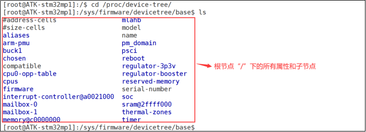
Figure 23.5.1 attributes and child nodes of the root node "/"
Figure 23.5.1 shows the contents of the directory / proc / device tree. Under the directory / proc / device tree are all attributes and child nodes of the root node "/". Let's take a look at these attributes and child nodes in turn.
1. Attributes of root node "/"
In the root file of figure 23, the attributes of "name",. 5 "#" cell ",. 5" # "are shown as the attributes of" 23-1 "#" cell ",. 5" # in the root file. Since it is a file, you can certainly view its contents. Enter cat command to view the contents of model and compatible. The results are shown in figure 23.5.2:
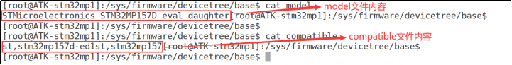
Figure 23.5.2 contents of model and compatible files
As can be seen from figure 23.5.2, the content of the file model is "STMicroelectronics stm32mp157d Eval daught", and the content of the file compatible is "St, stm32mp157d-ed1st,stm32mp157". Open the file stm32mp157d-atk DTS check. This is the model and compatible attribute value of the root node "/"!
2. Each child node of the root node "/"
Each folder in figure 23.5.1 is the child node of the root node "/", such as "aliases", "reboot", "chosen" and "cpus". You can check stm32mp157d ATK DTS and stm32mp157d ATK DTS refers to dtsi file to see what are the child nodes of the root node and whether they are consistent with those in figure 23.5.1.
/The proc / device tree directory is the embodiment of the device tree in the root file system. It is also organized according to the tree structure. Enter the / proc / device tree / soc directory to see all the child nodes of the soc node, as shown in figure 23.5.3:
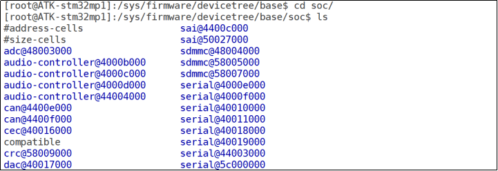
Figure 23.5.3 some SOC nodes
Like the root node "/", all files in figure 23.5.3 are the attribute files and child node folders of the soc node. You can check whether the contents of these property files are consistent with stm32mp151 The attribute values of soc nodes in dtsi are the same.
23.6 special nodes
There are two special child nodes in the root node "/": aliases and chosen. Let's take a look at these two special child nodes.
23.6.1 aliases child node
Open stm32mp157d ATK DTS file and aliases node are as follows:
Example code 23.6.1.1 aliases Child node
24      aliases {
25          serial0 = &uart4;
26      };
word alias
es means "alias". Therefore, the main function of aliases node is to define an alias. The purpose of defining an alias is to facilitate access to the node. However, we usually add a label when naming a node, and then access the node through & label, which is also very convenient. Moreover, a large number of nodes are accessed in the form of & label in the device tree.
23.6.2 chosen sub node
Chosen is not a real device. Chosen node is mainly used to transfer data from uboot to Linux kernel, with emphasis on the bootargs parameter. Average The chosen node in the dts file is usually empty or has little content, stm32mp157d ATK The content of chosen node in dts is as follows:
Example code 23.6.2.1 chosen Child node
20      chosen {
21          stdout-path = "serial0:115200n8";
22      };
From the example code 23.6.2.1, it can be seen that the chosen node only sets the attribute "stdout path", which means that the standard output uses serial0, while aliases has set serial0 to uart4, so uart4 is used as the default terminal after the development board is started. However, when we enter the / proc / device tree / choose directory, we will find that there is an additional attribute of bootargs, as shown in figure 23.6.2.1:

Figure 23.6.2.1 chosen node directory
Enter the cat command to view the contents of the bootargs file. The results are shown in figure 23.6.2.2:

Figure 23.6.2.2 contents of bootargs file
As can be seen from figure 23.6.2.2, the contents of the bootargs file are "console = ttystm0115200...", which is the bootargs environment variable set in uboot. Now there are two doubts:
① . we did not set the bootargs attribute of the chosen node in the device tree. How did the bootargs attribute in figure 23.6.2.1 come into being?
② Why are the contents of the bootargs file in figure 23.6.2.1 the same as the values of the bootargs environment variable in uboot? What is the relationship between them?
As mentioned in the previous explanation of uboot, when uboot starts the Linux kernel, it will pass the value of bootargs to the Linux kernel. Bootargs will be used as the command line parameter of the Linux kernel. When the Linux kernel starts, it will print the command line parameter (that is, the value of bootargs passed in by uboot), as shown in figure 23.6.2.3:

Figure 23.6.2.3 command line parameters
Since the bootargs attribute of the chosen node is not set in the device tree, there is only one possibility, that is, uboot added the bootargs attribute to the chosen node itself! And set the value of the bootargs attribute to the value of the bootargs environment variable. Because before starting the Linux kernel, only uboot knows the value of the bootargs environment variable, and uboot also knows The location of dtb device tree file in DRAM, so uboot is the most suspected of "committing a crime". Search the string "chosen" globally in the uboot source code to see if you can find some clues. As expected, in common / FDT_ support. The figure of "chosen" is found in the C file, FDT_ support. There is an FDT in the C file_ Chosen function. The contents of this function are as follows:
Example code 23.6.2.2 uboot In the source code fdt_chosen function
275 int fdt_chosen(void *fdt)
276 {
277     int   nodeoffset;
278     int   err;
279     char  *str;     /* used to set string properties */
280
281     err = fdt_check_header(fdt);
282     if (err < 0) {
283         printf("fdt_chosen: %s\n", fdt_strerror(err));
284         return err;
285     }
286
287     /* find or create "/chosen" node. */
288     nodeoffset = fdt_find_or_add_subnode(fdt, 0, "chosen");
289     if (nodeoffset < 0)
290         return nodeoffset;
291
292     str = getenv("bootargs");
293     if (str) {
294         err = fdt_setprop(fdt, nodeoffset, "bootargs", str,
295                   strlen(str) + 1);
296         if (err < 0) {
297             printf("WARNING: could not set bootargs %s.\n",
298                    fdt_strerror(err));
299             return err;
300         }
301     }
302
303     return fdt_fixup_stdout(fdt, nodeoffset);
304 }
Line 288, call the function fdt_find_or_add_subnode Slave device tree(.dtb)Found in chosen If the node is not found, it will create one by itself chosen Node.
Line 292, read uboot in bootargs Contents of environment variables.
Line 294, call the function fdt_setprop towards chosen Node addition bootargs Property, and bootargs The value of the attribute is the environment variable bootargs Content of the.
The evidence is "solid hammer", that is uboot Medium fdt_chosen Function in device tree chosen Added in node bootargs Property, and also set bootargs Property value. Next, let's follow fdt_chosen Function a little bit to see what functions have been called fdt_chosen,Always find the ultimate source. I won't show off here. I'll directly tell you how the whole process is, as shown in Figure 23.6.2.4:
Figure 23.6.2.4 FDT_ Call process of chosen function
The framed part in figure 23.6.2.4 is the function do_ bootm_ The execution flow of Linux functions, that is, do_bootm_linux functions will pass through a series of complex calls, and finally through FDT_ The chosen function adds the bootargs attribute to the chosen node. When we start the Linux kernel through the bootz command, we will run do_ bootm_ So far, the truth has been revealed. The source of everything comes from the following commands:
bootm c2000000 – c4000000
When we enter the above command and execute it, do_ The bootm function will execute, and then everything will start running according to the process shown in figure 23.6.2.4.
23.7 Linux kernel parsing DTB files
The Linux kernel will parse the DTB file when starting, and then generate the corresponding device tree node file in the / proc / device tree directory. Next, let's briefly analyze how the Linux kernel parses DTB files, as shown in figure 23.7.1:
Figure 23.7.1 device tree node analysis process.
As can be seen from figure 23.7.1, at start_ The kernel function completes the node analysis of the device tree, and the final actual function is unflatten_dt_node.
23.8 binding information document
The device tree is used to describe the device information on the board. Different devices have different information, which is reflected in the device tree as different attributes. So where do we look up the relevant instructions when we add a node corresponding to the hardware in the device tree? In the Linux kernel source code, there are detailed TXT documents describing how to add nodes. These TXT documents are called binding documents. The path is: Linux source code directory / Documentation/devicetree/bindings, as shown in figure 23.8.1:
Figure 23.8.1 binding document
For example, if we want to add a node under the I2C of STM32MP157 SOC, we can check the documentation / devicetree / bindings / I2C / i2c-stm32 Txt. This document describes in detail how the STM32MP1 series SOC adds an I2C device node to the device tree. The contents of the document are as follows:
- I2C controller embedded in STMicroelectronics STM32 I2C platform
Required properties:
- compatible: Must be one of the following
- "st,stm32f4-i2c"
- "st,stm32f7-i2c"
- "st,stm32mp15-i2c"
- reg: Offset and length of the register set for the device
- interrupts: Must contain the interrupt id for I2C event and then the
interrupt id for I2C error. - resets: Must contain the phandle to the reset controller.
- clocks: Must contain the input clock of the I2C instance.
- A pinctrl state named "default" must be defined to set pins in mode
of operation for I2C transfer. An optional pinctrl state named "sleep"
has to be defined as well as to put I2C in low power mode in suspend
mode. - #address-cells = <1>;
- #size-cells = <0>;
Optional properties:
- clock-frequency: Desired I2C bus clock frequency in Hz. If not specified,
the default 100 kHz frequency will be used.
For STM32F4 SoC Standard-mode and Fast-mode are supported, possible values are
100000 and 400000.
For STM32F7, STM32H7 and STM32MP1 SoCs, Standard-mode, Fast-mode and Fast-mode
Plus are supported, possible values are 100000, 400000 and 1000000. - dmas: List of phandles to rx and tx DMA channels. Refer to stm32-dma.txt.
- dma-names: List of dma names. Valid names are: "rx" and "tx".
- i2c-scl-rising-time-ns: I2C SCL Rising time for the board (default: 25)
For STM32F7, STM32H7 and STM32MP1 only. - i2c-scl-falling-time-ns: I2C SCL Falling time for the board (default: 10)
For STM32F7, STM32H7 and STM32MP1 only.
I2C Timings are derived from these 2 values - st,syscfg-fmp: Use to set Fast Mode Plus bit within SYSCFG when Fast Mode
Plus speed is selected by slave.
1st cell: phandle to syscfg
2nd cell: register offset within SYSCFG
3rd cell: register bitmask for FMP bit
For STM32F7, STM32H7 and STM32MP1 only. - st,smbus-alert: enable the SMBus Alert feature
- st,smbus-host-notify: enable the SMBus Host-Notify feature
- wakeup-source: Enable the possibility to use the I2C as a wakeup-source
For STM32H7 and STM32MP1 only.
Example:
i2c@40005400 {
    compatible = "st,stm32f4-i2c";
    #address-cells = <1>;
    #size-cells = <0>;
    reg = <0x40005400 0x400>;
    interrupts = <31>,
             <32>;
    resets = <&rcc 277>;
    clocks = <&rcc 0 149>;
    pinctrl-0 = <&i2c1_sda_pin>, <&i2c1_scl_pin>;
    pinctrl-names = "default";
};
i2c@40005400 {
    compatible = "st,stm32f7-i2c";
    #address-cells = <1>;
    #size-cells = <0>;
    reg = <0x40005400 0x400>;
    interrupts = <31>,
             <32>;
    resets = <&rcc STM32F7_APB1_RESET(I2C1)>;
    clocks = <&rcc 1 CLK_I2C1>;
    pinctrl-0 = <&i2c1_sda_pin>, <&i2c1_scl_pin>;
    pinctrl-1 =  <&i2c1_sda_pin_sleep>, <&i2c1_scl_pin_sleep>;
    pinctrl-names = "default", "sleep";
    st,syscfg-fmp = <&syscfg 0x4 0x1>;
    st,syscfg-fmp-clr = <&syscfg 0x44 0x1>;
};
Sometimes some chips are used in Documentation/devicetree/bindings If you can't find the corresponding document in the directory, you should consult the chip provider and ask them to provide you with the device tree file for reference.
23.9 common OF operation functions OF equipment tree
The device tree describes the detailed information OF the device, including digital type, string type and array type. We need to obtain this information when writing the driver. For example, the device tree uses the reg attribute to describe that the register address OF a peripheral is 0X02005482 and the length is 0X400. When writing the driver, we need to obtain the values OF 0X02005482 and 0X400 OF the reg attribute, and then initialize the peripheral. The Linux kernel provides us with a series OF functions to obtain the node or attribute information in the device tree. These functions all have a unified prefix "OF_", So it is also called OF function in many data. These OF function prototypes are defined in include / Linux / OF H file.
23.9.1 finding OF function OF node
Devices are "hung" to the device tree in the form of nodes. Therefore, in order to obtain other attribute information of the device, you must first obtain the node of the device. The Linux kernel uses device_node structure, which is defined in the file include / Linux / of H, defined as follows:
Example code 23.3.9.1 device_node node
51  struct device_node {
52      const char *name;               	/*Node name      		*/
53      phandle phandle;
54      const char *full_name;          	/*Node full name      		*/
55      struct fwnode_handle fwnode;
56
57      struct  property *properties;   /*attribute            	*/
58      struct  property *deadprops;    /*removed attribute   	*/
59      struct  device_node *parent;    /*Parent node     		*/
60      struct  device_node *child;     /*Child node     		*/
61      struct  device_node *sibling;
62  #if defined(CONFIG_OF_KOBJ)
63      struct  kobject kobj;
64  #endif
65      unsigned long _flags;
66      void    *data;
67  #if defined(CONFIG_SPARC)
68      unsigned int unique_id;
69      struct of_irq_controller *irq_trans;
70  #endif
71  };
There are five OF functions related to finding nodes. Let's take a look in turn.
1,of_find_node_by_name function
of_ find_ node_ by_ The name function searches the specified node by node name. The prototype of the function is as follows:
struct device_node *of_find_node_by_name(struct device_node *from,
const char *name);
Function parameters and return values have the following meanings:
From: the node to start searching. If NULL, it means to start searching the entire device tree from the root node.
Name: the name of the node to find.
Return value: the node found. If NULL, the search fails.
2,of_find_node_by_type function
of_find_node_by_type function through device_ The type attribute finds the specified node. The function prototype is as follows:
struct device_node *of_find_node_by_type(struct device_node *from, const char *type)
Function parameters and return values have the following meanings:
From: the node to start searching. If NULL, it means to start searching the entire device tree from the root node.
Type: the type string corresponding to the node to be searched, that is, device_type attribute value.
Return value: the node found. If NULL, the search fails.
3,of_find_compatible_node function
of_find_compatible_node function according to device_ The type and compatible attributes find the specified node. The function prototype is as follows:
struct device_node *of_find_compatible_node(struct device_node *from,
const char *type,
const char *compatible)
Function parameters and return values have the following meanings:
From: the node to start searching. If NULL, it means to start searching the entire device tree from the root node.
Type: the type string corresponding to the node to be searched, that is, device_type attribute value, which can be NULL, indicating that device is ignored_ Type attribute.
Compatible: the list of compatible attributes corresponding to the node to be found.
Return value: the node found. If NULL, the search fails
4,of_find_matching_node_and_match function
of_find_matching_node_and_match function through of_device_id matching table to find the specified node. The function prototype is as follows:
struct device_node *of_find_matching_node_and_match(struct device_node *from,
const struct of_device_id *matches,
const struct of_device_id **match)
Function parameters and return values have the following meanings:
From: the node to start searching. If NULL, it means to start searching the entire device tree from the root node.
matches: of_device_id matching table, that is to find nodes in this matching table.
Match: match of found_ device_ id.
Return value: the node found. If NULL, the search fails
5,of_find_node_by_path function
of_ find_ node_ by_ The path function finds the specified node through the path. The prototype of the function is as follows:
inline struct device_node *of_find_node_by_path(const char *path)
Function parameters and return values have the following meanings:
Path: the node name with the full path. You can use the alias of the node. For example, "/ backlight" is the full path of the backlight node.
Return value: the node found. If NULL, the search fails
Parent / child function OF 23.9 OF
The Linux kernel provides several OF functions to find the parent node or child node corresponding to the node. Let's take a look in turn.
1,of_get_parent function
of_ get_ The parent function is used to obtain the parent node (if any) of the specified node. The prototype of the function is as follows:
struct device_node *of_get_parent(const struct device_node *node)
Function parameters and return values have the following meanings:
Node: the node of the parent node to find.
Return value: found parent node.
2,of_get_next_child function
of_ get_ next_ The child function uses iterative to find child nodes. The prototype of the function is as follows:
struct device_node *of_get_next_child(const struct device_node *node,
struct device_node *prev)
Function parameters and return values have the following meanings:
Node: parent node.
prev: the previous child node, that is, from which child node to start iterative search for the next child node. It can be set to NULL, indicating that it starts from the first child node.
Return value: the next child node found.
23.9.3 OF function for extracting attribute value
The attribute information of the node stores the contents required by the driver, so it is very important to extract the attribute value. The Linux kernel uses the structure property to represent the attribute, which is also defined in the file include / Linux / of H, as follows:
Example code 23.9.3.1 property structural morphology
31  struct property {
32      char    *name;          		/* Attribute name         	*/
33      int 	length;            	 	/* Attribute length         	*/
34      void    *value;         		/* Attribute value          	*/
35      struct property *next;  		/* Next attribute      	*/
36  #if defined(CONFIG_OF_DYNAMIC) || defined(CONFIG_SPARC)
37      unsigned long _flags;
38  #endif
39  #if defined(CONFIG_OF_PROMTREE)
40      unsigned int unique_id;
41  #endif
42  #if defined(CONFIG_OF_KOBJ)
43      struct bin_attribute attr;
44  #endif
45  };
The Linux kernel also provides the OF function to extract attribute values. Let's take a look in turn.
1,of_find_property function
of_ find_ The property function is used to find the specified property. The prototype of the function is as follows:
property *of_find_property(const struct device_node 	*np,
				  	  const char 				*name,
				  	  int 					*lenp)
Function parameters and return values have the following meanings:
np: Device node.
name:  Attribute name.
lenp: Number of bytes of attribute value
 Return value: the property found.
2,of_property_count_elems_of_size function
of_ property_ count_ elems_ of_ The size function is used to obtain the number of elements in the attribute. For example, if the value of reg attribute is an array, you can use this function to obtain the size of this array. The prototype of this function is as follows:
int of_property_count_elems_of_size(const struct device_node 	*np,
							  const char 				*propname,
						  	  int 					elem_size)
Function parameters and return values have the following meanings:
np: Device node.
proname:  Attribute name that needs to count the number of elements.
elem_size: Element length.
Return value: the number of attribute elements obtained.
3,of_property_read_u32_index function
of_ property_ read_ u32_ The index function is used to obtain the U32 type data value (unsigned 32 bits) of the specified label from the attribute. For example, if an attribute has multiple U32 type values, you can use this function to obtain the data value of the specified label. The prototype of this function is as follows:
int of_property_read_u32_index(const struct device_node 	*np,
				          const char 				*propname,
				          u32	 				index,
						  u32 					*out_value)
Function parameters and return values have the following meanings:
np: Device node.
proname:  The name of the property to read.
index: The label of the value to be read.
out_value: Read value
 Return value: 0 read successfully, negative value, read failed,-EINVAL Indicates that the property does not exist,-ENODATA Indicates that there is no data to read,-EOVERFLOW Indicates that the list of attribute values is too small.
4,	of_property_read_u8_array function
   	of_property_read_u16_array function
of_property_read_u32_array function
of_property_read_u64_array function
These four functions are used to read the array data of u8, u16, u32 and u64 types in the attribute respectively. For example, most reg attributes are array data. You can use these four functions to read all the data in the reg attribute at one time. The prototypes of these four functions are as follows:
int of_property_read_u8_array(const struct device_node 	*np,
						 const char 				*propname,
						 u8 					*out_values,
						 size_t 					sz)
int of_property_read_u16_array(const struct device_node 	*np,
						  const char 				*propname,
						  u16 					*out_values,
						  size_t 					sz)
int of_property_read_u32_array(const struct device_node 	*np,
			       	      const char 				*propname,
						  u32 					*out_values,
			       	      size_t 					sz)
int of_property_read_u64_array(const struct device_node 	*np,
			       	      const char 				*propname,
						  u64 					*out_values,
			              size_t 					sz)
Function parameters and return values have the following meanings:
np: Device node.
proname:  The name of the property to read.
out_value: The array values read are u8,u16,u32 and u64.
sz: The number of array elements to read.
Read success, negative value: 0, read failure,-EINVAL Indicates that the property does not exist,-ENODATA Indicates that there is no data to read,-EOVERFLOW Indicates that the list of attribute values is too small.
5,of_property_read_u8 function
of_property_read_u16 function
of_property_read_u32 function
of_property_read_u64 function
Some attributes have only one integer value. These four functions are used to read such attributes with only one integer value. They are used to read u8, u16, u32 and u64 attribute values respectively. The function prototype is as follows:
int of_property_read_u8(const struct device_node 	*np,
					 const char 				*propname,
			 		 u8 					*out_value)
int of_property_read_u16(const struct device_node 	*np,
					 const char 				*propname,
			 		 u16 					*out_value)
int of_property_read_u32(const struct device_node 	*np,
					 const char 				*propname,
			 		 u32 					*out_value)
int of_property_read_u64(const struct device_node 	*np,
					 const char 				*propname,
			 		 u64 					*out_value)
Function parameters and return values have the following meanings:
np: Device node.
proname:  The name of the property to read.
out_value: Array value read.
Return value: 0, reading succeeded, negative value, reading failed,-EINVAL Indicates that the property does not exist,-ENODATA Indicates that there is no data to read,-EOVERFLOW Indicates that the list of attribute values is too small.
6,of_property_read_string function
of_property_read_string The function is used to read the string value in the attribute. The prototype of the function is as follows:
int of_property_read_string(struct device_node *np,
const char *propname,
const char **out_string)
Function parameters and return values have the following meanings:
np: device node.
proname: the name of the attribute to be read.
out_string: the read string value.
Return value: 0, reading succeeded, negative value, reading failed.
7,of_n_addr_cells function
of_ n_ addr_ The cells function is used to obtain #address cells attribute value. The prototype of the function is as follows:
int of_n_addr_cells(struct device_node *np)
Function parameters and return values have the following meanings:
np: device node.
Return value: the obtained value of the #address cells attribute.
8,of_n_size_cells function
of_ n_ size_ The cells function is used to obtain #size cells attribute value. The prototype of the function is as follows:
int of_n_size_cells(struct device_node *np)
Function parameters and return values have the following meanings:
np: device node.
Return value: the obtained value of the #size cells attribute.
23.9.4 other commonly used OF functions
1,of_device_is_compatible function
of_ device_ is_ The compatible function is used to check whether the compatible attribute of the node contains the string specified by compat, that is, to check the compatibility of the device node. The prototype of the function is as follows:
int of_device_is_compatible(const struct device_node *device,
const char *compat)
Function parameters and return values have the following meanings:
Device: device node.
compat: the string to view.
Return value: 0. The compatible attribute of the node does not contain the string specified by compat; Positive number. The compatible attribute of the node contains the string specified by compat.
2,of_get_address function
of_ get_ The address function is used to obtain address related attributes, mainly the value of "reg" or "assigned addresses". The function attributes are as follows:
const __be32 *of_get_address(struct device_node *dev,
int index,
u64 *size,
unsigned int *flags)
Function parameters and return values have the following meanings:
dev: device node.
index: address label to be read.
size: address length.
flags: parameters, such as IORESOURCE_IO,IORESOURCE_MEM et al
Return value: the first address of the read address data. If it is NULL, it means that the reading fails.
3,of_translate_address function
of_ translate_ The address function is responsible for converting the address read from the device tree into a physical address. The prototype of the function is as follows:
u64 of_translate_address(struct device_node *dev,
const __be32 *addr)
Function parameters and return values have the following meanings:
dev: device node.
in_addr: address to be converted.
Return value: the physical address obtained. If it is OF_BAD_ADDR indicates conversion failure.
4,of_address_to_resource function
IIC, SPI, GPIO and other peripherals have corresponding registers. These registers are actually a group of memory space. The Linux kernel uses the resource structure to describe a section of memory space, "resource" translates into "resources". Therefore, the resource structure describes the device resource information, and the resource structure is defined in the file include / Linux / ioport H, defined as follows:
Example code 23.9.4.1 resource structure
20 struct resource {
21 resource_size_t start;
22 resource_size_t end;
23 const char *name;
24 unsigned long flags;
25 unsigned long desc;
26 struct resource *parent, *sibling, *child;
27 };
For 32-bit SOC, resource_size_t is of type u32. Where start represents the start address, end represents the end address, name is the name of the resource, flags is the resource flag bit, which generally represents the resource type, and the optional resource flag is defined in the file include / Linux / ioport H, as follows:
Example code 23.9.4.2 Resource flag
1  #define IORESOURCE_BITS      		0x000000ff
2  #define IORESOURCE_TYPE_BITS		0x00001f00
3  #define IORESOURCE_IO        		0x00000100
4  #define IORESOURCE_MEM       		0x00000200
5  #define IORESOURCE_REG       		0x00000300
6  #define IORESOURCE_IRQ       		0x00000400
7  #define IORESOURCE_DMA       		0x00000800
8  #define IORESOURCE_BUS       		0x00001000
9  #define IORESOURCE_PREFETCH 		0x00002000
10 #define IORESOURCE_READONLY 		0x00004000
11 #define IORESOURCE_CACHEABLE 	0x00008000
12 #define IORESOURCE_RANGELENGTH 	0x00010000
13 #define IORESOURCE_SHADOWABLE  	0x00020000
14 #define IORESOURCE_SIZEALIGN 	0x00040000
15 #define IORESOURCE_STARTALIGN  	0x00080000
16 #define IORESOURCE_MEM_64    		0x00100000
17 #define IORESOURCE_WINDOW    		0x00200000
18 #define IORESOURCE_MUXED 			0x00400000
19 #define IORESOURCE_EXCLUSIVE 	0x08000000
20 #define IORESOURCE_DISABLED  	0x10000000
21 #define IORESOURCE_UNSET 			0x20000000
22 #define IORESOURCE_AUTO      		0x40000000
23 #define IORESOURCE_BUSY      		0x80000000
The most common resource sign is IORESOURCE_MEM,IORESOURCE_REG and IORESOURCE_IRQ Wait. Next, let's go back to of_address_to_resource Function. The name of this function is like extracting resource values from the device tree, but it is essentially reg Property value, and then convert it to resource Structure type and function prototype are as follows
int of_address_to_resource(struct device_node	*dev,
					  int 				index,
				   	  struct resource 		*r)
Function parameters and return values have the following meanings:
dev: device node.
index: address resource label.
r: The resource value of the obtained resource type.
Return value: 0, successful; Negative value, failed.
5,of_iomap function
of_ The iomap function is used for direct memory mapping. Previously, we used to use the ioremap function to complete the mapping from physical address to virtual address. After using the device tree, we can directly use the of function_ The iomap function is used to obtain the virtual address corresponding to the memory address. There is no need to use the ioremap function. Of course, you can also use the ioremap function to complete the memory mapping from physical address to virtual address. However, after adopting the device tree, most drivers use of_iomap function. of_ The iomap function essentially converts the address information in the reg attribute into a virtual address. If the reg attribute has multiple segments, you can specify which segment to complete the memory mapping through the index parameter, of_ The prototype of iomap function is as follows:
void __iomem *of_iomap(struct device_node 	*np,
					 int 				index)
Function parameters and return values have the following meanings:
np: Device node.
index: reg Property, if reg Property has only one paragraph index It is set to 0.
Return value: the first address of virtual memory after memory mapping. If it is NULL If yes, the memory mapping fails.
Common about device tree OF That's all for the function, Linux About device tree in kernel OF Functions are not only mentioned above, but also many OF We didn't explain these functions OF The function should be combined with the specific driver, such as the method of obtaining the interrupt number OF Function, get GPIO of OF Functions and so on, these OF The function will be explained in detail in the later driving experiment.
That's all for the equipment tree. We need to know more about the equipment tree:
① The difference between, dts, dtb and DTC and how to dts files are compiled into dtb file.
② , device tree syntax, which is the key point, because we need to modify the device tree in practical work.
③ Several special sub nodes of the tree.
④ . the OF operation function OF the device tree is also the focus, because the device tree is ultimately used by the driver file, and the driver file must read the attribute information in the device tree, such as memory information, GPIO information, interrupt information, etc. If you want to read the attribute value OF the device tree in the driver, you must use many OF functions provided by the Linux kernel.
Starting from the next chapter, all Linux driver experiments will use the device tree, from the most basic lighting to complex audio, network or block devices. We will lead you from simplicity to depth, deeply analyze the device tree, and finally master the driving development skills based on the device tree.