1) Experimental platform: punctual atom STM32MP157 development board
2) Purchase link: https://item.taobao.com/item.htm?&id=629270721801
3) Full set of experimental source code + manual + video download address: http://www.openedv.com/thread-318813-1-1.html
4) Official station B of punctual atom: https://space.bilibili.com/394620890
5) Punctual atom STM32MP157 technical exchange group: 691905614

Chapter 43 external RTC chip PCF8563 experiment
In the previous chapter, we learned the built-in RTC peripherals of STM32MP1 and understood the RTC driver framework under Linux system. In general applications, the RTC built in SOC can be used, and the cost is low. However, in some occasions with high requirements for time accuracy, the RTC built in SOC is not applicable. At this time, we need to select the appropriate external RTC chip according to our own application requirements. A RTC chip PCF8563 is loaded on the STM32MP1 development board of punctual atom, which is an external RTC chip with IIC interface. In this chapter, we will learn how to drive the external RTC chip.
43.1 PCF8563 introduction
43.1.1 PCF8563 introduction
PCF8563 is a CMOS RTC chip, which supports time and calendar functions, programmable clock output, interrupt output and low voltage detection. PCF8563 provides a two-wire IIC interface to transmit time information. The maximum transmission speed is 400Kbit/S. when reading and writing registers, the address increases automatically. The relevant characteristics of PCF8563 are as follows:
① Provide year, month, day and week, hour, minute and second timing, and use an external 32.768Khz crystal oscillator.
② . low backup current: 0.25uA, VDD=3.0V, temperature 25 ℃.
③ IIC interface, with a maximum speed of 400KHz.
④ Programmable clock output, which can be used by other equipment. The output clock frequencies include 32.768kHz, 1.024kHz, 32Hz and 1Hz.
⑤ Support alarm clock and timing function.
⑥ The IIC read address is 0XA3 and the write address is 0XA2, that is, the IIC device address is 0X51.
⑦ , there is an interrupt pin with an open drain output.
The block diagram of PCF8563 is shown in figure 43.1.1.1:
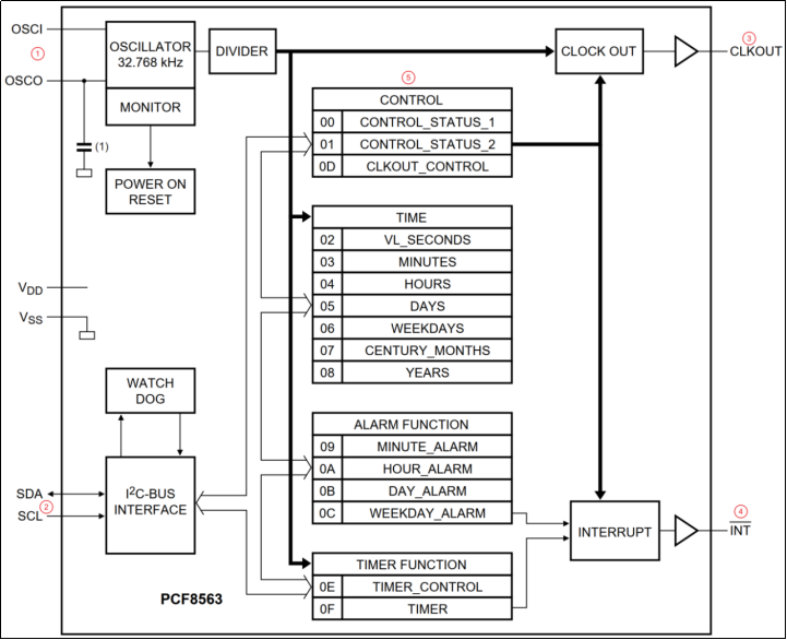
Figure 43.1.1.1 PCF8563 block diagram
Briefly analyze the block diagram in figure 43.1.1.1 below:
① This is the 32.768kHz crystal oscillator pin of PCF8563. PCF8563 must be externally connected with 32.768kHz crystal oscillator.
② This is the IIC pin of PCF8563. PCF8563 communicates with the main control through the IIC interface. Therefore, PCF8563 is essentially an IIC device.
③ Clock output pin.
④ . interrupt pin.
⑤ As mentioned earlier, PCF8563 is an IIC device, so there are many internal registers to realize RTC Functions, such as configuring chips, reading time information, etc. This part is the internal register of PCF8563. We will analyze the internal register of PCF8563 in detail later.
43.1.2 PCF8563 register details
PCF8563 has 16 internal registers, all of which are 8 bits. The first two registers (0x00 and 0x01) are control / status registers. 0X020X08 are time and date registers. These registers store the information of seconds, minutes, hours, days, weeks, months and years. 0X090X0C is the alarm register, which saves the alarm information. 0X0D is the clock output frequency register, and 0X0E and 0X0F are the clock control registers. Note that time information such as hour, minute, second, year, day, and alarm clock is in BCD format.
Next, let's look at how these registers are used:
1. Control status register 1(0X00)
The first is the status register. The register structure is shown in figure 43.1.2.1:

Figure 43.1.2.1 control status register 1
Figure 43.1.2.1 shows the control status register 1, and the corresponding bit meanings are as follows:
TEST1(bit7): 0, normal mode; 1. Test mode.
N(bit6,bit4,bit2~0): not used.
STOP(bit5): 0, RTC clock runs; 1. RTC clock stops.
TESTC(bit3): 0, normal mode, turn off POR overwrite; 1. Enable POR override.
2. Control status register 2(0X01)
Next, take a look at the control status register 2. The register structure is shown in figure 43.1.2.2:

Figure 43.1.2.2 control status register 2
Figure 43.1.2.2 shows the control status register 2, and the corresponding bit meanings are as follows:
N(bit7~5): not used.
TI_TP(bit4): when it is 0, the INT pin depends on the TF bit. When it is 1, the INT pin outputs pulses of the specified frequency.
AF(bit3): alarm clock flag bit. If it is 1, it indicates that the alarm clock occurs, write 0 is cleared, and write 1 is invalid.
TF(bit2): timer flag bit. If it is 1, it indicates that timing occurs, write 0 is cleared, and write 1 is invalid.
AIE(bit1): alarm clock interrupt enable bit, 0, turn off alarm clock interrupt; 1. Enable the alarm clock to interrupt.
TIE(bit0): timer interrupt enable bit, 0, close timer interrupt; 1. Enable timer interrupt.
3. Time and date register (0X02~0X08)
Next, take a look at the time and date related registers. There are seven registers in total, and the structure is shown in figure 43.1.2.3:
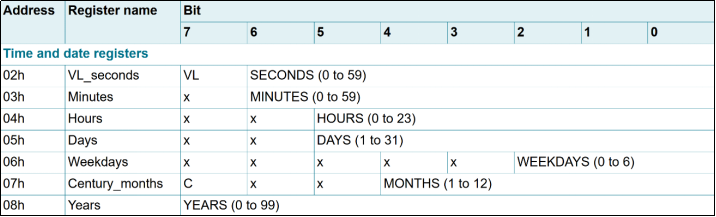
Figure 43.1.2.3 time and date register
Let's take a look at these registers in figure 43.1.2.3 in turn:
0X02: this register is a second register. PCF8563 has low voltage detection. When the VDD voltage is lower than the minimum allowable voltage, the VL(bit) bit will be set to 1, indicating that the clock is abnormal. If the voltage is normal, it will be 0. The 7 bits of SECONDS(bit60) represent the specific number of seconds. The range is 059. It is in BCD format.
0X03: this register is a minute register. The seven bits of MINUTES(bit60) are valid, indicating the specific number of minutes. The range is 059 and is in BCD format.
0X04: this register is an hour register. The six bits of HOURS(bit50) are valid, indicating the specific number of hours. The range is 023, in BCD format.
0X05: this register is a date register. The six bits of DAYS(bit50) are valid, indicating the specific hours. The range is 131, in BCD format.
0X06: this register is the week register. The three bits WEEKDAYS(bit20) are valid, indicating the specific week. The range 06 is in BCD format.
0X06: this register is the week register. The three bits WEEKDAYS(bit20) are valid, indicating the specific week. The range 06 is in BCD format. 0 is Sunday, 1 is Monday, and so on. 6 is Saturday.
0X07: this register is the month register, where C(bit7) is the century flag bit. If it is 1, it means 20xx, and if it is 0, it means 19xx. The five digits of MONTHS(bit40) are valid, indicating the specific month, ranging from January to December, in BCD format.
0X08: this register is a year register. The 8 bits of YEARS(bit70) are valid, indicating the specific year. The range is 099.
4. Alarm register (0X09~0X0C)
Next, take a look at the alarm clock related registers. There are four registers in total, and the structure is shown in figure 43.1.2.4:
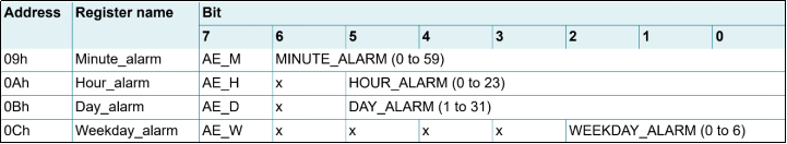
Figure 43.1.2.4 alarm clock register
Let's take a look at these registers in figure 43.1.2.4 in turn:
0X09: this register is the alarm minute register, AE_M(bit7) is the enable bit of the minute alarm clock. If it is 0, the minute alarm clock is enabled, and if it is 1, it is turned off. MINUTE_ The 7 bits of alarm (bit60) represent the specific alarm minutes, with a range of 059, in BCD format.
0X0A: this register is an alarm clock hour register, and its meaning is similar to that of 0X09 register.
0X0B: this register is an alarm date register, and its meaning is similar to that of 0X09 register.
0X0C: this register is an alarm date register, and its meaning is similar to that of 0X09 register.
In addition, there are clock output register (0X0D) and timer register (0X0E and 0X0F). Here we don't need the clock output and timer function of PFC8563, so we won't explain it here. If you are interested, please refer to PCF8563 data manual.
Generally speaking, PCF8563 is very simple. It is an RTC chip with IIC interface. Therefore, two types of drivers are involved in Linux system:
① IIC driver requires IIC driver framework to read and write PCF8563 chip.
② RTC driver, because it is an RTC chip, RTC driver framework is used.
If you want to use the interrupt function, you also need to use the interrupt subsystem in the Linux system. We have the corresponding experimental explanation before. Therefore, the linux driver of PCF8563 is not complex, and the key point is that the PCF8563 driver has been integrated by default in the Linux system. It is very simple for us to use. We can directly modify the device tree, add PCF8563 node information, and then enable the PCF8563 driver of the kernel.
43.2 hardware schematic analysis
The schematic diagram of PCF8563 is shown in figure 43.2.1:
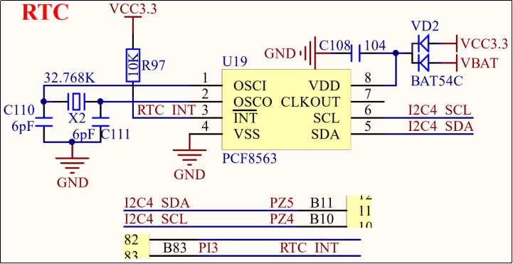
Figure 43.2.1 schematic diagram of PCF8563
As can be seen from figure 43.2.1, PCF8563 is connected to the I2C4 interface of STM32MP157, and the pins are PZ5 and PZ4. In addition, the INT pin of PCF8563 is connected to the PI3 pin of STM32MP157.
43.3 experiment driven compilation
43.3.1 modify equipment tree
1. Add or find the pinmux configuration of the IO used by PCF8563
As mentioned earlier, the IIC interface of PCF8563 is connected to I2C4 of STM32MP157, and the corresponding pins are PZ4 and PZ5. In addition, there is an interrupt pin PI3. First, we need to add the configuration information corresponding to these three pins in the device tree. First add PZ4 and PZ5 and open stm32mp15 pincrtl Dtsi file to find out whether there is I2C4 pin configuration information. It is available by default. The contents are as follows:
Example code 43.3.1.1 i2c4 Pin node
1  i2c4_pins_a: i2c4-0 {
2   	pins {
3       		pinmux = <STM32_PINMUX('Z', 4, AF6)>, 		/* I2C4_SCL 	*/
4            		  <STM32_PINMUX('Z', 5, AF6)>; 	/* I2C4_SDA 	*/
5       		bias-disable;
6       		drive-open-drain;
7      	 	slew-rate = <0>;
8   	};
9  };
10
11 i2c4_pins_sleep_a: i2c4-1 {
12  	pins {
13      	pinmux = <STM32_PINMUX('Z', 4, ANALOG)>, 	/* I2C4_SCL 	*/
14           		  <STM32_PINMUX('Z', 5, ANALOG)>; 	/* I2C4_SDA 	*/
15  	};
16 };
As can be seen from lines 3 and 4, I2C4 The default pin is PZ4 and PZ5,It's the same as our experiment, so I2C4 The pin of does not need us to modify and can be used directly i2c4_pins_a Just. Next, you need to define the interrupt pin PI3 As the previous pin, if GPIO This pin may not be added for the function pinctrl Information.
2. Add pinmux under I2C4 node and add pcf8563 child nodes
As mentioned earlier, the PCF8563 driver has been integrated into the Linux kernel, so there must be documents describing how to use this driver. Open documentation / devicetree / bindings / RTC / PCF8563 Txt, this document describes how to use the PCF8563 driver of the Linux kernel, and also gives the reference device node. Please refer to this document.
At stm32mp157d ATK DTS file, add I2C4 node, and add the following contents:
Example code 43.3.1.3 Add pcf8563 node
1  &i2c4 {
2   	pinctrl-names = "default", "sleep";
3      	pinctrl-0 = <&i2c4_pins_a>;
4   	pinctrl-1 = <&i2c4_pins_sleep_a>;
5   	status = "okay";
6
7       	pcf8563@51{
8          	compatible = "nxp,pcf8563";
9          	irq_gpio = <&gpioi 3 IRQ_TYPE_EDGE_FALLING>;
10         	reg = <0x51>;
11  	};
12 };
second~4 Row, setting IO To use pinmux to configure.
Lines 7 to 10 are the child nodes of pcf8563 device. In line 8, set the compatible to "nxp,pcf8563". This is necessary, otherwise it cannot match the pcf8563 driver of linux kernel. From line 9, set the pcf8563 interrupt pin to PI3 and trigger the falling edge. The I2C address of pcf8563 is 0X51, so reg is 0X51.
43.3.2 PCF8563 drive enable
1. Turn off the built-in RTC drive of STM32MP157
In the last experiment, we enabled the internal RTC of STM32MP157. In order to prevent interference, we need to turn off the internal RTC first! The configuration path is:
-> Device Drivers
-> Real Time Clock
->STM32 RTC / / uncheck
As shown in figure 43.3.2.1:
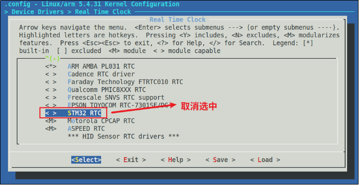
Figure 43.3.2.1 close the internal RTC of STM32MP157
2. Enable PCF8563 driver of Linux kernel
Next, you need to enable the PCF8563 driver that comes with the linux kernel. The configuration path is as follows:
-> Device Drivers
-> Real Time Clock
->< * > Philips PCF8563 / Epson rtc8564 / / select PCF8563
As shown in figure 43.3.2.2:
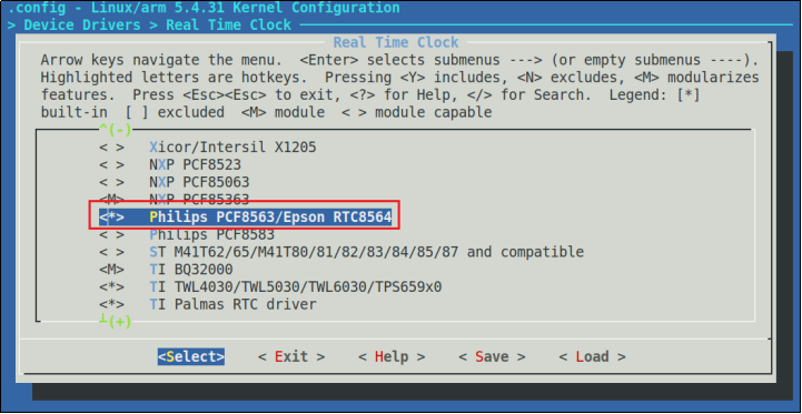
Figure 43.3.2.2 enable PCF8563 drive
After configuration, recompile the kernel and device tree to get new uImage and stm32mp157d ATK dtb.
43.4 operation test
Use the kernel and device tree compiled above to launch the development board. When the system is started for the first time and we do not set the PCF8563 time, the startup process will prompt the information as shown in figure 43.4.1:

Figure 43.4.1 PCF8563 startup process
It can be seen from figure 43.4.1 that the system has identified PCF8563, indicating that the drive is OK. However, it is suggested that low voltage is detected, and the date and time are invalid. This is because we have not set the time. After the system is started successfully, then refer to the method in the previous chapter to set the RTC time. For example, I set the time here as May 21, 2021, 15:52:00 p.m. and enter the following command:
date -s "2021-05-21 15:52:00" / / set the time
Hwlock - w / / save
Restart the system after the time is set. At this time, the system log information is shown in figure 43.4.2:

Figure 43.4.2 PCF8563 startup information
As can be seen from figure 43.4.2, at this time, the PCF8563 no longer prompts the error of low voltage, and correctly reads the time information. After the whole development board is powered off, the PCF8563 will continue to count, because there is a button battery power supply.
43.5 PCF8563 drive analysis
In the previous section, we have tested PCF8563. In this section, we will take a brief look at the PCF8563 driver source code. According to the compatible attribute value in line 8 of example code 43.3.1.3, we can find the corresponding driver file. Search the string "nxp,pcf8563" in the linux source code to find the corresponding driver file. The driver file is drivers / RTC / rtc-pcf8563 c.
PCF8563 is an I2C device, so the basic driving frame is I2C, which is in rtc-pcf8563 C the following contents can be found in the document:
Example code 43.5.1 pcf8563 I2C Drive frame
1  static const struct i2c_device_id pcf8563_id[] = {
2   	{ "pcf8563", 0 },
3   	{ "rtc8564", 0 },
4   	{ }
5  };
6  MODULE_DEVICE_TABLE(i2c, pcf8563_id);
7
8  #ifdef CONFIG_OF
9  static const struct of_device_id pcf8563_of_match[] = {
10  	{ .compatible = "nxp,pcf8563" },
11  	{ .compatible = "epson,rtc8564" },
12  	{ .compatible = "microcrystal,rv8564" },
13 	 	{}
14 };
15 MODULE_DEVICE_TABLE(of, pcf8563_of_match);
16 #endif
17
18 static struct i2c_driver pcf8563_driver = {
19  	.driver     = {
20      	.name   = "rtc-pcf8563",
21      	.of_match_table = of_match_ptr(pcf8563_of_match),
22  	},
23  	.probe      = pcf8563_probe,
24  	.id_table   = pcf8563_id,
25 };
26
27 module_i2c_driver(pcf8563_driver);
The above example code is a standard I2C driver framework, PCF8563 on lines 9 to 14_ of_ The match structure array is the device tree matching array. The compatible attribute on line 10 is "nxp,pcf8563", which matches our device tree. Match PCF8563 in line 23_ The probe function will execute.
Next, let's take a look at pcf8563_probe function. The source code of the function is as follows (with abbreviations):
Example code 43.5.2 pcf8563_probe function
1  static int pcf8563_probe(struct i2c_client *client,
2               const struct i2c_device_id *id)
3  {
4   struct pcf8563 *pcf8563;
5   int err;
6   unsigned char buf;
......
13  pcf8563 = devm_kzalloc(&client->dev, sizeof(struct pcf8563),
14              GFP_KERNEL);
15  if (!pcf8563)
16      return -ENOMEM;
17
18  i2c_set_clientdata(client, pcf8563);
19  pcf8563->client = client;
20  device_set_wakeup_capable(&client->dev, 1);
21
22  /* Set timer to lowest frequency to save power */
23  buf = PCF8563_TMRC_1_60;
24  err = pcf8563_write_block_data(client, PCF8563_REG_TMRC, 1, &buf);
25  if (err < 0) {
26      dev_err(&client->dev, "%s: write error\n", __func__);
27      return err;
28  }
29
30  /* Clear flags and disable interrupts */
31  buf = 0;
32  err = pcf8563_write_block_data(client, PCF8563_REG_ST2, 1, &buf);
33  if (err < 0) {
34      dev_err(&client->dev, "%s: write error\n", __func__);
35      return err;
36  }
37
38  pcf8563->rtc = devm_rtc_allocate_device(&client->dev);
39  if (IS_ERR(pcf8563->rtc))
40      return PTR_ERR(pcf8563->rtc);
41
42  pcf8563->rtc->ops = &pcf8563_rtc_ops;
43  /* the pcf8563 alarm only supports a minute accuracy */
44  pcf8563->rtc->uie_unsupported = 1;
45  pcf8563->rtc->range_min = RTC_TIMESTAMP_BEGIN_2000;
46  pcf8563->rtc->range_max = RTC_TIMESTAMP_END_2099;
47  pcf8563->rtc->set_start_time = true;
48
49  if (client->irq > 0) {
50      err = devm_request_threaded_irq(&client->dev, client->irq,
51              NULL, pcf8563_irq,
52              IRQF_SHARED | IRQF_ONESHOT | IRQF_TRIGGER_LOW,
53              pcf8563_driver.driver.name, client);
54      if (err) {
55          dev_err(&client->dev, "unable to request IRQ %d\n",
56                              client->irq);
57          return err;
58      }
59  }
60
61  err = rtc_register_device(pcf8563->rtc);
62  if (err)
63      return err;
......
70  return 0;
71 }
Line 13, request memory, rtc-pcf8563.c Defines a pcf8563 Structure to describe PCF8563 Chip, so here is to apply for one pcf8563 example.
twenty-third~36 Line, initialization PCF8563.
Line 38, pcf8563 There is a in the structure rtc Member variable, which is a rtc_device Structure pointer. You should be familiar with this. This is what we explained in the previous chapter RTC The core of the driving framework rtc_device. There's a need for this rtc Pointer allocates memory.
Line 588, setting rtc_device of ops The member variable is pcf8563_rtc_ops,pcf8563_rtc_ops Contains PCF8563 Specific operations, including setting time, reading time, setting alarm clock, etc.
590th~593 OK, continue initialization rtc Other member variables.
595th~605 Line, interrupt initialization, PCF8563 There is an interrupt pin INT,Therefore, the interrupt function can be used. Use here devm_request_threaded_irq Function completion interrupt application has been initialized. The interrupt function is pcf8563_irq.
Line 607, call rtc_register_device Function register with system rtc_device,that is pcf8563.
To sum up, pcf8563_probe The core of function is initialization PCF8563,Then use the previous chapter RTC Drive frame to set PCF8563,Then register with the kernel.
Next, let's look at the core of PCF8563: pcf8563_rtc_ops, as follows:
Example code 43.5.3 pcf8563_rtc_ops
1 static const struct rtc_class_ops pcf8563_rtc_ops = {
2   	.ioctl      	= pcf8563_rtc_ioctl,
3   	.read_time  	= pcf8563_rtc_read_time,
4   	.set_time   	= pcf8563_rtc_set_time,
5   	.read_alarm 	= pcf8563_rtc_read_alarm,
6   	.set_alarm  	= pcf8563_rtc_set_alarm,
7   	.alarm_irq_enable = pcf8563_irq_enable,
8 };
pcf8563_rtc_ops Provided PCF8563 Time and alarm clock read-write operation function, application pair PCF8563 All operations of are finally completed through these functions. Let's take the reading time as an example, when the application reads PCF8563 At the current time,.read_time It will be executed. Here it is pcf8563_rtc_read_time,The function source code is as follows(With Ellipsis):
Example code 43.5.4 pcf8563_rtc_read_time function
1  static int pcf8563_rtc_read_time(struct device *dev,
struct rtc_time *tm)
2  {
3   	struct i2c_client *client = to_i2c_client(dev);
4   	struct pcf8563 *pcf8563 = i2c_get_clientdata(client);
5  	 	unsigned char buf[9];
6   	int err;
7
8   	err = pcf8563_read_block_data(client, PCF8563_REG_ST1, 9, buf);
9   	if (err)
10     		return err;
11
12  	if (buf[PCF8563_REG_SC] & PCF8563_SC_LV) {
13      	pcf8563->voltage_low = 1;
14      	dev_err(&client->dev,
15          		"low voltage detected, date/time is not reliable.\n");
16      	return -EINVAL;
17  	}
......
28  	tm->tm_sec = bcd2bin(buf[PCF8563_REG_SC] & 0x7F);
29  	tm->tm_min = bcd2bin(buf[PCF8563_REG_MN] & 0x7F);
30  	tm->tm_hour = bcd2bin(buf[PCF8563_REG_HR] & 0x3F);
31  	tm->tm_mday = bcd2bin(buf[PCF8563_REG_DM] & 0x3F);
32  	tm->tm_wday = buf[PCF8563_REG_DW] & 0x07;
33  	tm->tm_mon = bcd2bin(buf[PCF8563_REG_MO] & 0x1F) - 1; ,
34  	tm->tm_year = bcd2bin(buf[PCF8563_REG_YR]) + 100;
35  	/* detect the polarity heuristically. see note above. */
36  	pcf8563->c_polarity = (buf[PCF8563_REG_MO] & PCF8563_MO_C) ?
37      	(tm->tm_year >= 100) : (tm->tm_year < 100);
......
45  	return 0;
46 }
Line 8, use pcf8563_read_block_data Function from PCF8563_REG_ST1 register(Address is 0 X00)At the beginning, the data of 9 registers are read continuously. So you can get PCF8563 The values of the control and status registers 1 and 2, and the event and date registers.
Line 12, judgment PCF8563 0 of X02 register VL Whether the bit is 1, that is, check PCF8563 Whether it is in low voltage mode and whether the event and date are valid.
226th~232 Row, get in sequence PCF8563 The time and date values in are used here bcd2bin Function will be the original BCD Value is converted to a time value. Pack the acquired time and date into parameters tm In, tm It's a rtc_time Structure pointer variable.
Line 234, judge 0 X07 Register C position(bit7)If this bit is 1, it means 20 xx In, if it is 0, it is 19 xx Year.
It can be seen that pcf8563_rtc_read_time The function is very simple, which is to read PCF8563 Internal time and date values, and then package them into rtc_time Inside. Other functions are similar. You can analyze them by yourself. I won't explain them here.
So far, PCF8563 The simple analysis of the driver is completed. Others IIC Interfaced RTC Chip drivers are basically similar. You can choose the right one in the actual project development RTC Chip.